GENERAL ECOLOGY SEAGULL IV X-6 Operating manual

Installation Instructions
CONGRATULATIONS! You have just purchased a General
Ecology, Inc. SEAGULL®IV X-6 Water Purification System
employing the most advanced, effective and reliable
technology available.The features of this equipment are
indicated in product literature accompanying each Unit. It
is recommended that you briefly study this literature
before beginning your installation. Please note that the
SEAGULL®IV X-6 Unit features top mounted, NPT
threaded ports that are available in either ¾ or 1 inch
sizes. Be sure you have the proper size for your
installation (normally ¾ inch for residential applications).
Sweat-type copper inlet and outlet adapter/connectors are
also available upon request.
Multiple Units can be installed in parallel to increase flow
rate (for industrial, commercial and special applications),
or in series for special requirements such as pre-filtration
followed by submicron microfiltration (
Figure 1
).
Installation is straightforward and is easily accomplished
by persons experienced in plumbing installation. A ½"
“deep” socket will facilitate V-clamp Nut removal and
replacement and is recommended.
Series Installation
SUPPLY (IN)
Use same pipe sizes throughout.
Figure 1
SUPPLY (IN)
SERVICE (OUT)
SERVICE (OUT)
1½" LINE
Parallel Installation
Made in the USA
SEAGULL®IV X-6 DRINKING WATER
PURIFICATION SYSTEM
INSTALLATION AND
PRODUCT USE GUIDE
AS9100, ISO 9001 and FAA Quality Certified Original Equipment and PMA Manufacturer

SEAGULL®IVX-6 PartsList andDimensions
AssemblyInstructions
should be applied to center Port O-Rings of Housing
Cover before aligning it with the Cartridge Module.
7. Center the Cover on the Module while aligning it with the
Bowl Flange and press down into position.
8. Install V-clamp and tighten while lightly tapping the
outside of the V-clamp outside the bolt. A light coating of
petroleum jelly applied to the insides of the V-clamp
segments will ease the Clamp installation.
9. Note the Unit Cover’s Supply (INLET) Port and Service
(OUTLET) Port. On all General Ecology stainless steel
Units the Port closest to the side is the Supply (INLET)
Port and the center Port is the Service (OUTLET) Port.
1. Remove the stainless steel Housing and the Cartridge
Module from the package.
2. Remove the V-band that secures the Housing Cover
and Bowl by removing ½" Nut with a wrench or ½" deep
socket.
3. Carefully raise the Cover, being careful not to dent or cut
the Bowl Flange, nor allow dirt on any of the Gaskets.
4. Lower the Cartridge Module into the Bowl until it sits on
top of the Rubber Pedestal.
5. Be sure Gaskets are clean and free of cuts and other
potential leak paths.
6. For ease of installation, a light coating of petroleum jelly
EquipmentPlacement
The SEAGULL®IV X-6 Unit should be level and should
have adequate vertical clearance to permit the three (3)
Dielectric Positioning Pads to be positioned under each
Unit. It is important to use these Pads to allow vertical
clearance for the Unit to clear the Inlet and Outlet
Connectors during servicing. Additionally, the Pads
eliminate potential electrical interface between the Unit and
the floor.
Installation with flexible lines will allow easy positioning of
unit and facilitate future servicing.
The Unit should always be placed on the Service
(OUTLET) side, rather than the Supply (INLET) side, of the
air pressure tanks used with on-site water supplies. See
Figure 2
.
1 Cover with NPT ports 1 N/A
2 Bowl 1 100300
3 V-Clamp 1 100400
4 Housing Gasket 1 100455
5 Module Outlet Port (center)
Seal O-Rings (Internal) 2 100414
6 Dielectric Positioning Pads 3 100421
7 V-Clamp Hex Nut 1 100402
8 RS-6SG Module 1 100501
9 Pedestal Assembly 1 100424
No. Description Qty. Part No.
SPARK-L-PURE®
METERING
PUMP
(If Required)
SUPPLY (IN)
"TEE" PressureTank Installation
SPARK-L-PURE®
METERING
PUMP
(If Required)
SUPPLY (IN)
Figure 2
SERVICE
(OUT)
SERVICE
(OUT)
IN/OUT PressureTank Installation
1
3
4
16.25" *
(38.1 cm)
1"
(2.5 cm)
15"
(38.1 cm)
1.25"
(3.2 cm)
* Assembled Dimensions
2
7
8
6
5
9
* Assembled
Dimensions

Installation Considerations
Valves should be placed in series with the Supply
(INLET) and Service (OUTLET) Lines as shown in
Figure 3
. A Flow Controller, if necessary, should be
placed in the Supply Line to help limit flow surges
due to trapped air and other possible causes. A
Check Valve should be placed in the Service Line to
protect the Unit from back pressure surges.
A By-pass Valve should be installed the Inlet and
Outlet Lines. The by-pass valve can be opened to
allow an uninterrupted water supply while the
system is being serviced.
The SEAGULL®IV X-6 Unit is compact, relatively
lightweight and is easily disconnected from the
plumbing lines. It is not necessary to service the
Unit in place; for convenience, it can be carried to a
nearby sink, floor drain, or even outside. Adequate
clearance should be provided around the installed
Unit for ease of movement and to allow servicing on
other pieces of equipment when necessary.
Obviously, the Unit should not be allowed to freeze.
1. Select location and position Unit as desired.
2. Close Supply and Service Valves to isolate the
plumbing at the installation point.
3. Dry-fit the plumbing fittings and pieces necessary to
install the Unit and cut or unthread existing plumbing
lines as appropriate.
4. Connect all joints where applicable. Do not allow
excess heat to reach any seals or gaskets and be
sure solder does not reach the ball or seal of any
valves.
5. In order to avoid the possibility of connecting the
SEAGULL®IV X-6 Unit in the reverse direction, be
sure to label the Supply (INLET) and Service
(OUTLET) pipes.
6. Flush plumbing lines to remove any construction
debris. Close By-pass valve.
7. Position the SEAGULL®IV X-6 Unit, and start the
threads of the Closure Nuts. Place the Positioning
Pads underneath the Unit and raise it to the proper
elevation to eliminate strain on the Inlet and Outlet
Ports, and only tighten the Inlet Port Nut at this time.
9.
Slowly
open the Supply Line Valve allowing water to
enter the Unit.Trapped air will exhaust through the
loosely connected Outlet Port until the Unit fills. When
water starts to flow from the Outlet:
a. Close the Inlet Valve.
b. Snugly tighten the Outlet Closure Nut.
c. Open the Outlet Valve.
d. Reopen the Inlet Valve to place the
SEAGULL®IV X-6 Unit in service.
9. Check carefully for leaks or seepage around any of the
joints or connections and correct as necessary.
10. Allow water to run for three to five minutes to remove
air and particles from the new module.
Installation Instructions
FLOW
CONTROLLER
CHECK
VALVE
BY-PASS
VALVE
INLET
SUPPLY
(IN)
OUTLET
SERVICE
(OUT)
Figure 3
FLEXIBLE
LINES
Recommended,
not included
QUESTIONS?
Call 1-800-441-8166
in USA/Canada
for Customer Service

Service Instructions
The SEAGULL®IV X-6 Purification System, furnished with General Ecology, Inc.’s RS-6SG Cartridge
Module, should require little or no service other than an occasional Module replacement.The need for
changing the Module will be apparent from an obviously reduced flow rate due to clogging. Service should be
accomplished by the following procedure.
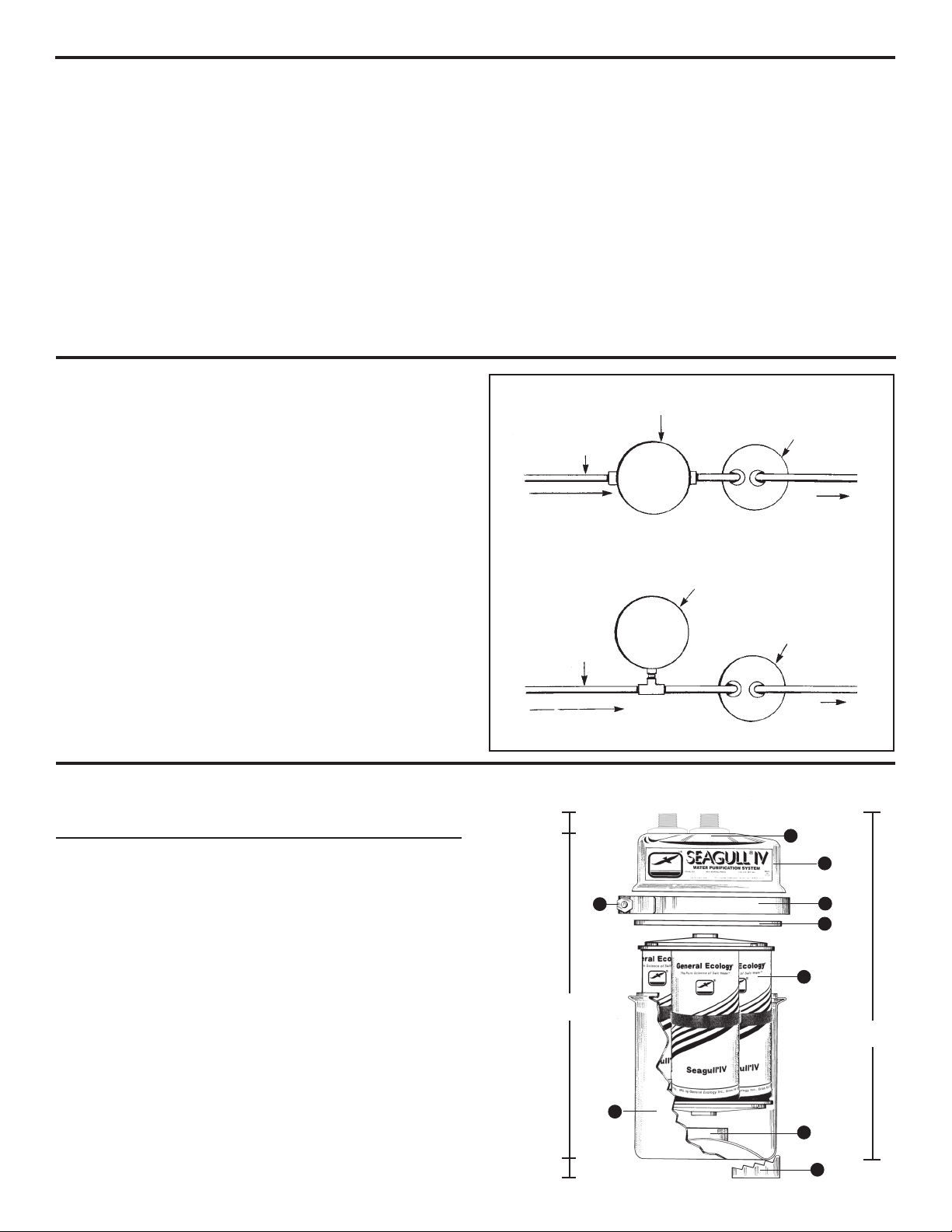
IMPORTANT: In order to avoid reinstalling the Unit in the reverse direction, the Inlet and Outlet Pipes should
be labeled prior to disconnecting the unit. On all General Ecology stainless steel Pressure Vessels, the
Port closest to the Vessel Cover’s side is the Supply (INLET) Port and the center Port is the Service
(OUTLET) Port.
Disassembly
Removing Module from Unit:
1. Close supply, open downstream valve or faucet to
relieve pressure, then close service line valves. Loosen
Closure Nuts and gradually remove Dielectric
Positioning Pads to lower Unit to supporting surface.
2. Place Unit over drain or a container to catch excess
water as the V-clamp is removed, and remove V-clamp.
3. Carefully raise the Cover from the Unit and remove the
Cartridge Module. (We recommend the use of rubber
gloves to protect the skin from direct contact with the
potential concentration of impurities that may be on the
outside of the Cartridge Module.) Dump excess water
from the Bowl and rinse clean. Be careful not to dent or
cut the Bowl Flange, nor cut, nor allow dirt on any of
the Gaskets.
4. Be sure the Rubber Pedestal is properly in place on the
raised center of the Bowl bottom.
5. Be sure Gaskets are clean and free of cuts and other
potential leak paths.
6. For ease of installation look inside of cover for center
port O-rings and apply a light coating of petroleum jelly
before aligning and re-inserting the cartridge module.
7. Lower new RS-6SG cartridge module into bowl.
8. Center the Cover on the Module while aligning it with
the Bowl Flange and press down into position.
9. Install V-clamp and tighten (do not over tighten) while
lightly tapping the outside of the V-clamp (not on the
bolt). A light coating of petroleum jelly applied to the
insides of the V segments will ease clamp installation.
Reinstallation
Placing the Unit back in service:
1. Reposition the Unit per initial installation, being careful
to replace the Closure Nut Gaskets properly and to
position the Unit to eliminate strain on the Service and
Supply Lines. Only tighten the Inlet Port Nut at
this time.
2.
Slowly
open the Supply Line Valve allowing water to
enter the Unit.Trapped air will exhaust through the
loosely connected Outlet Port until the Unit fills. When
water starts to flow from the Outlet:
a. Close the Inlet Valve.
b. Snugly tighten the Outlet Closure Nut.
c. Open the Outlet Valve.
d. Reopen the Inlet Valve to place the
SEAGULL®IV X-6 Unit in service.
3. Allow water to run for three to five minutes to remove
air and particles from the new module.
200123A 03/09
©1996, General Ecology, Inc. ®, ™ registered trademarks of General Ecology, IncAll health claims not in accordance with local or state laws are hereby withdrawn. EPA Reg. No. 37403-PA-01
V-CLAMP
MODULE
DIELECTRIC PAD
HOUSING COVER
V-CLAMP NUT
HOUSING BOWL
OUTLET NPT PORT
(610)363-7900-fax(610)363-0412
www.generalecology.com
QUESTIONS?
Call 1-800-441-8166
in USA/Canada
for Customer Service
HOUSING
GASKET
AS9100, ISO 9001 and FAA Quality Certified
Original Equipment and PMA Manufacturer
Table of contents
Other GENERAL ECOLOGY Water Filtration System manuals
Popular Water Filtration System manuals by other brands

optrel
optrel TH3P instruction manual

Parker
Parker Racor 120R-RAC-01 Instruction

3M
3M AP11T Installation and operating instructions

Crystal Quest
Crystal Quest CQE-SP-00809 Installation and operation guide

Zodiac Pool Systems
Zodiac Pool Systems DuoClear 200 Installation and operation manual

Acqua Brevetti
Acqua Brevetti BRAVOFIL FT020 Installation and operating manual