GENERAL ECOLOGY SEAGULL IV Select Operating manual

200796
INSTALLATION AND PRODUCT USE GUIDE
General Ecology, Inc.
151 Sheree Blvd.
Exton, PA 19341
www.generalecology.com
610-363-7900
A Loar Group Company
System Model Seagull IV Select X1-PB
Part No. 702040
Replacement Element PB-1SG
Part No. 788080
Max Pressure 860 kPa (125 psig)
Max Temperature 38°C (100 °F)
Rated Service Flow 3.8 L/min (1 gpm)
Rated Capacity 3,800 Liters (1,000 gallons)
For Cold Water Use.
System Tested and Certified by NSF International against NSF/ANSI Standard 42 and
53 for the reduction of lead, cysts, chlorine, taste and odor.
This system should be installed to comply with state and local laws and regulations
After installation of a new cartridge the system should be flushed at full flow rate for six (6) minutes
to purge air and fines from the system.
Cartridge capacity will be effected by source water quality and system operating conditions
Do not use with water that is microbiologically unsafe or of unknown quality without adequate
disinfection before or after the system.
Systems certified for cyst reduction may be used on disinfected waters that may contain filterable cysts.
Cartridge should be replaced after 1,000 gallons, annually, when flow rate decreases or if unusual
taste or odor is observed.
Replacement cartridges are available from your local distributor or from General Ecology, Inc.
se agull
®
IV
•
Select

2
1 36” Female Compression Thread 2 800354
3/8” Braided Connector Hose
2 Mounting Bracket Kit with
2 Mounting screws (Residential) 1 700063
3 PB-1SG Cartridge with Gasket (10) 1 788080
4 X-1 Pressure Vessel 1 770080
5 Housing Gasket 1 710562
6 V-Clamp for Housing 1 710534
7 Wing Nut for V-Clamp 1 710032
8 Faucet, FP Threaded 1 707206
9 Faucet Mounting Nut 1 707106
Optional Accessories Not Included
11 Bracket Mounting Clip with 1 700060
3 Screws (RV/Marine)
12 6” Female Compression Thread 1 810820
3/8” Braided Connector Hose
with Male 3/8” Compression Tee
No. Description Qty. Part No.
9
8
1
2
4
5
3
6
7
Figure 1
1. Open Canister. Remove
V-Clamp and separate
Pressure Vessel upper and
lower halves.
2. Remove Cover. Remove
small plastic protective cover
from your new cartridge
by pulling the tab end up
(Fig.1a).
4. Install Cartridge. Thread
Cartridge (Fig.3) into top
half of Pressure Vessel (Be
careful not to cross thread)
until contact is first made with
Rubber Seal. Then tighten ¼
turn only. Do not overtighten.
Be sure Pressure Vessel
Flanges and Housing Gasket
are clean and free of dents,
nicks or cuts.
5. Reassemble Pressure Vessel.
Place Gasket on Flange of
lower half of Pressure Vessel
(Fig.4) and reassemble
V-Clamp, keeping Seagull IV
logo upright. The Wing Nut
on the Clamp should be
tightened snugly, by hand
only. Use no tools to tighten.
V-Clamp
Housing
Gasket
Flange
Figure 4
Cartridge
Figure 3
1a
General Installation Instructions Please retain for future servicing of your SEAGULL®IV Water System
SEAGULL®IV •Select System Parts List
Visit our web site and order online at
www.generalecology.com
11
12
10
Figure 2
3. Install Cartridge Gasket.
Install the Cartridge Gasket
into place (Fig. 2) by pushing
the gasket onto the the inside
center port on the top half
of the housing until firmly
seated against the inside
surface of the vessel. Be sure
the open end/double ridge
side contacts the stainless
surface (see Fig. 2).
Double
Ridge
Seal
Cut Out
Push
Onto
Center
Port

3
Exclusive Feature — TOP MOUNT FAUCET
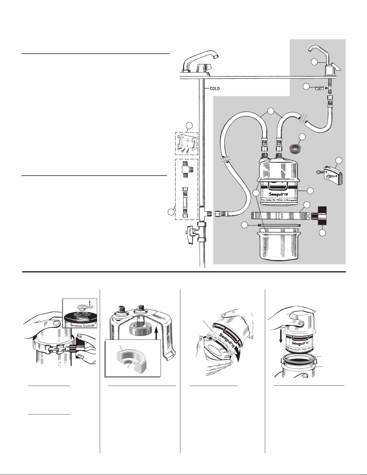
Figure 5
6. Install Mounting Bracket. Position
black Mounting Bracket on the inside
wall of the sink cabinet. Use the two
Self-Tapping Screws to securely install
the Bracket. (figure 4). Make sure the
Bracket location permits access to the
cold water valve location and easy
access for Cartridge changes.
7. Install Faucet. The System is furnished
with General Ecology’s exclusive “Top
Mount” Ceramic Disc Faucet. If a
suitable hole isn’t available, prepare a
¾” hole to install your faucet. Refer to
Mounting Pattern below.
Sinks and counter tops made of
porcelain, stainless steel, stone or man-
made material require special care. We
suggest you consult the manufacturer’s
guidelines or contact your dealer for
best results in drilling the ¾” hole
necessary to mount the faucet. Be sure
sink/counter top surface at drill hole is
flat and burr free.
To change “pull direction” of handle
on faucet, lift handle off stem and
reposition stainless steel pin to
alternate location. Reinstall handle.
Stainless
steel pin
Place Pin on right
or left side
Mounting Hole Pattern
for FP Faucet
.75” (1.9 cm.)
Hole Diameter
1.9” (4.8 cm)
Base Diameter
8. Connect Hose directly to Faucet Stem
and tighten securely by hand. Do not
overtighten. Insert and thread Spout
into base, Do not over tighten (figure
5). Drop free end of Connector Hose
through previously prepared hole and
position Faucet in hole.
Threaded
Spout
Figure 7
9.
Mount Faucet. Slide open side of Faucet
Mounting Nut onto reduced diameter,
un-threaded section of Faucet Stem now
beneath the sink/counter (Fig. 6). Slide
the Nut upwards to contact the threads.
Then carefully engage the threads, being
careful to not cross thread. Hand tighten
as necessary to hold the Faucet in place,
Do not use tools and do not overtighten.
Check alignment and position of Faucet,
and adjust as necessary.
Figure 8
10. Connect Inlet and Outlet lines. Connect
free end of the Hose from Faucet
Stem to Outlet (center) Port on the
Pressure Vessel. Tighten securely. Do
not overtighten. Connect remaining
Hose from fitting on cold water supply
line to Inlet (outside) Port on top of
Pressure Vessel. Do not overtighten.
Inlet Line
connects
to Cold Water
Supply.
Outlet Line
connects to
Water Faucet.
Inlet Line
Outlet Line
11. Mount unit on Bracket by placing the
V-Clamp over the raised section on
top of the Bracket. Open the Faucet to
allow air to exhaust slowly. Open Valve
on cold water service line. Check for
leaks. Allow water to run for several
minutes to clear line and system of air
and any loose materials. Please note
that for the first few days you may see
entrapped air bubbles within the water.
This is perfectly normal and will cease
after the unit has processed several
gallons of water. Also, some black
“fines” from inside of cartridge may
flow with the first few gallons of water.
These are harmless, if consumed.
Figure 9
QUESTIONS?
Visit www.generalecology.com
or Call 1-800-441-8166
for Customer Service
Figure 6

General Ecology, Inc. purifiers feature stainless steel pressure
vessels and ports. Faucets are manufactured with the finest
components available. If properly cared for, these finishes can
provide a lifetime of elegance. Chrome finishes can be damaged
by abrasive cleaners, in spite of their hardness. To clean surfaces
properly, use a small amount of a non-abrasive liquid detergent
and a soft wet cloth. Gently rub the soiled surface until the dirt
is removed. Then rinse clean and wipe with a dry soft cloth to
remove water drops and to prevent spotting. Do not use any
abrasive or pumice type cleansers to clean the surfaces of faucets,
or you may permanently scratch or otherwise damage the faucet
coating. Hard water may leave mineral deposits or “water spots”.
If not cleaned regularly, these deposits may resist cleaning with
simple liquid detergents. These can usually be removed using a
small amount of vinegar applied directly and rubbing with a soft
cloth. Heavy deposits may require repeated applications.
SEAGULL®IV •Select Dimensions and Care Instructions
©2018 General Ecology, Inc. • ®-™ Trademarks of General Ecology, Inc. • All health claims not in accordance with local or state laws are hereby withdrawn. • 200796
AS9100D: 2016, EN9001D: 2016, JISQ9100: 2016, ISO9001: 2015
Original Equipment and FAA PMA Manufacturer
4
1.9”
(4.8 cm)
FP FAUCET
.725”
(1.9 cm)
7.4”
(18.8 cm)
6.0”
(15.3 cm)
2.1”
(5.3 cm)
4.1”
(10.4 cm)
2.9”
(7.3 cm)
5”
(12.7 cm)
4.1”
(10.5 cm)
5.4”
(13.7 cm)
2.5”
(6.4 cm)
PRESSURE VESSEL
max 1.4”
(3.6 cm)
.3.9” (9.9 cm)
For Warranty Information: See warranty card supplied with system.
General Ecology, Inc.
A Loar Group Company
Other GENERAL ECOLOGY Water Filtration System manuals