General Hobby CITABRIA-120 User manual

Warning! This model is not a toy.
It is designed for maximum performance. Please seek for advice
if one is not familiar with this kind of engine-powered precise
model. Operating this model without prior preparation may
cause injuries .Remember, safety is the most important thing.
Always keep this instruction manual at hand for quick reference.
Specifications
Wing Span 105.5in/2680mm
Wing Area 1596.5 sq in/103sq dm
Flying Weight 14.3lb/6500g
Fuselage Length 65in/1655mm
Engine 50CC gas engine
Radio 4channels 6 servos
CITABRIACITABRIA
ARF

Pay close attention here
Apply C.A Glue
Assemble left and right
sides the same way
Drill holes with thespecified
diameter (here: 2mm)
Ensure smooth non-binding
movement while assembling
Cut off shadedportion
Apply A.B Glue
Purchase separately
2mm
A
B
P.A
C.A
1.Read through the manual before you begin, so you
will have an overall idea of what to do.
2.Check all parts. If you find any defective or missing
parts contact your local dealer. Please DRY FIT and
check for defective for all parts that will require CA
or Epoxy for final assembly. Any parts you find to be
defective after the gluing process may be difficult to
remove for warranty replacement. The manufacturer
will replace any defective parts,but will be difficult to
extend to the good parte that are good before gluing to
defective parts during assembly.
3. Symbols used throughout this instruction manual
comprise,
R
L
PART LIST------------------------------------------P.1
BEFORE YOU BEGINNING--------------------P.1
SAFETY PRECAUTION--------------------------P.1
ASSEMBLY-------------------------------------P.2-P.7
INDEXINDEX
INDEXINDEX
SAFETY PRECATIONSAFETY PRECATION
BEFORE YOU BEGINNINGBEFORE YOU BEGINNING
CITABRIA-120CITABRIA-120
P.1
Warning!
Important Safety Precautions
#First time flyer should never fly by himself/herself.
Assistance from experienced flyer is absolutely
necessary.
#Pre-flight adjustment must be done before flying ,
it is very dangerous to fly a badly pre-adjusted
aircraft.
#Citabria is specially designed to be powered by
50cc engine, using a more powerful engine does
not mean better performance. In fact, over powered
engine may cause severe damage and injuries.
#Make sure the air field is spacious ,never fly the
plane too close to people and never get too close
to a running propeller.
#If you find wrinkles on the covering as a result of
weather changes you can use hot iron to remove
the wrinkles. Please begin with lower temperature
setting and gradually raise the temperature until
the wrinkles are gone. Too hot an iron may damage
the covering.
#Check and re-tighten up all factory assembled
screws ,use thread locker if applicable.

INSTALLING THE AILERONSINSTALLING THE AILERONS
INSTALL AILERON PUSHRODSINSTALL AILERON PUSHRODS
INSTALL AILERON SERVOINSTALL AILERON SERVO
1. Connect aileron with wing by five hinges each
side. There are five slot on the wing and aileron.
Half hinges insert in to wings and half to aileron.
2. Test fit the ailerons to the wing with the hinges.
If the hinges does not remain centered. Stick a pin
through the middle of the hinge to hold it in position.
3.Remove any pins you may have inserted into the
hinges. Adjust the aileron so there is a small gap
between the aileron and the wing. The gap should be
small, just enough to see light through or to slip a
piece of paper through.
4.Apply six dropsof thin CAto the top and bottom
of each hinge.Do not useCA accelerator. Afterthe
CA hasfully hardened, testthe hinges bypulling on
the aileron.
5. Repeat thisprocedure for installing the right
aileron.
Do the left wing first soyour work matches the
photos the firsttime through. Youcan do onewing
at a time,or work on them together.
1. Position a small nylon control horn on the aileron
positioning it as shown in the sketch and aligning it
with the servo. Mark the location fro the screw holes.
Drill through the marks you made with a drill bit.
Mount the nylon control horn to the aileron by
inserting three machine screws through the control
horn and into the nylon mounting plate on the top
of the aileron.
Pushrod wirePushrod wire
FasLinkFasLink
Servo hornServo horn
1.6mm1.6mm
2, Locate apushrod wire threaded on one end.
Thread a nylonclevis onto the threaded end of
the wire 20turns. Install a silicone clevis retainer
onto the clevis.Then install the clevis on the
aileron control horn.
3. Be surethe aileron servo is centered. Enlarge
the hole inthe servo arm with a HobbicoServo
Horn Drill. Centerthe aileron and align the wire
pushrod with thehole in the end of theservo arm.
Using a marker, mark thelocation where the wire
aligns with thehole in the servo arm onthat mark
a 90 bend.From the bend measure an additional
9.5mm and thecut off the excess pushrod wire.
4.Install the wireinto the hole in the servoarm
using a nylon FasLink as shownin the sketch.
P.2
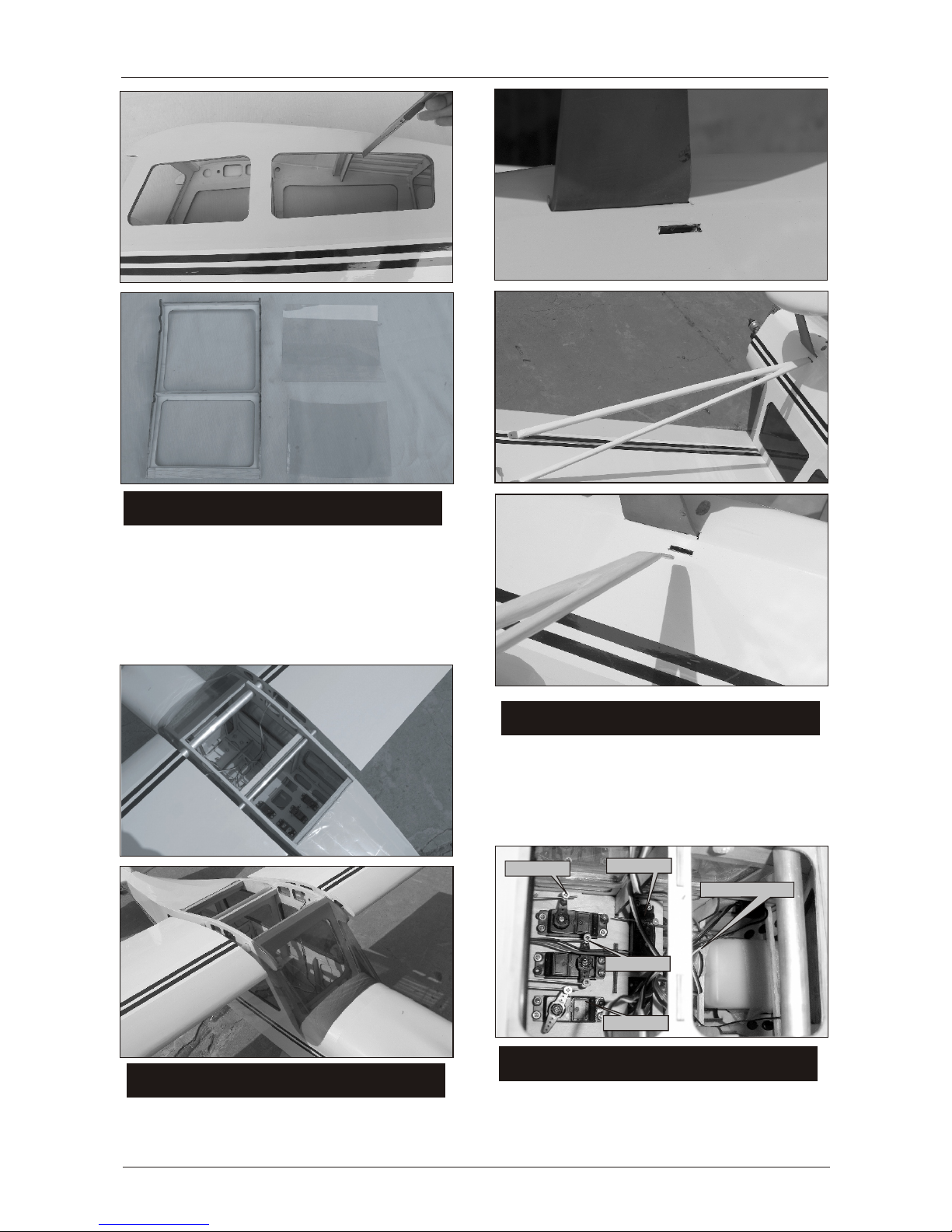
1. The slot for servoinstallation is already laser cut
you just needto cut off the coveringwith knife.
2. Use foursheet metal screws to attach theservo to
the wing.
3.Pull the servowire out the root of thewing.
4. Repeat thisprocedure for installingthe right
wing.
CITABRIA-120CITABRIA-120

INSTALL ELEVATORINSTALL ELEVATOR
INSTALL RUDDERINSTALL RUDDER
JOIN RUDDER AND FUSELAGEJOIN RUDDER AND FUSELAGE
Install the rudderto stab with three hinges. Using
the same installationmethod usedon theailerons.
1. Examine thetail of fuselage,there are twoslots
for installation elevatorand rudder.First, cut the
cover with knifeat the tail of fuselage asshown the
next pictures.
P.3
INSTALL ELEVATOR&RUDDER PUSHRODSINSTALL ELEVATOR&RUDDER PUSHRODS
Examine the tail of fuselage, there are four slots.
Two for elevator servo pushrods installation, the
rest for rudder servo horn.
3. Put outthe elevator, cut off the covering with
knife along theline.
4. Insert theelevator to the slot again, gluethe
elevator to thefuselage with epoxy.
2. Insert theelevator to the slot, make theleft and
right are equal.Then drawing two lines along
the joining atfuselage and elevator.
1. Examine thetail of fuselage. There are two slots
each side youneed to cut off the covering.
2. Put therudder into the slot you justcut off. Draw
a line according to the joining at rudder and
fuselage. Then put the rudder out and cutoff the
covering along theline you drew. This procedure is
necessary cause therudder will easy move if youdo
not peel off the covering.
3. Put therudder into the slot again. Glueit to the
fuselage with epoxy.
Insert the elevatorto the fuselage. Using the same
installation method usedon the rudder. Please
reference the nextpictures.
CITABRIA-120CITABRIA-120

P.4
INSTALL THE TAIL WHEELINSTALL THE TAIL WHEEL
Use three sheetmetal screws to attach the tail
wheel bracket tothe tail of fuselage. Then attach
the other sideto the rudder. The tail wheel can
move with therudder moving .
INSTALL THE MAIN LANDING GEARINSTALL THE MAIN LANDING GEAR
INSTALL ENGINEINSTALL ENGINE
1. Molded intothe firewall are lines that arefor
referencing the locationof the enginemount
template. Using afelt-tip pen, drawthrough the
line extending themfurther out toeach side ofthe
firewall.
1. Examine themiddle of the fuselage. There are
two slots eachside. Cut off the coveringwith knife
first. The longer one forlanding gear installation.
The smaller onefor wing struts installation.
2. Atthe bottom ofthe middle of the fuselage, there
are eight roundslot. You need tocut off the covering
too.
2. Drill fourpilot hole through each of themarks
in the cornersof the pattern.
1. There are four tubes from the slots to the engine
room directly. You need insert four wires from
engine room out of the slot at the tail of fuselage.
2. Install the elevator and rudder servo pushrods.
Using the same installation method used on the
aileron servo pushrods.
Please reference the next pictures.
3. Fix four struts on the elevator with screws. The
bottom are same. Please reference the next pictures.
3. Insert the main landing gear bracket into the
longer slot . Thenfix the bracket with fuselage with
screws. Please reference the next pictures.
3. Use foursheet metal screws to attach themount.
CITABRIA-120CITABRIA-120

P.5
4. Position your engine onto the engine mount.
With the engine resting on the engine mount rails.
Center the engine and engine mount. Then tighten
the engine mount bolts. With your engine still resting
on the rails, position the engine so that the distance
from the firewall to the front of the engine thrust
washer is 145mm. With the engine properly
positioned, resting on the engine mount, slide the
cowl onto the fuselage to be sure the engine is
extending out of the cowl far enough.
5. Using the engine as a guide, mark the four holes
for the engine bolts on the engine mount. Install the
engine onto the engine mount. Drill four holes in
the mount. Drill four holes in the mount. Then, use
a tap to thread the holes.
INSTALL FUEL TANKINSTALL FUEL TANK
Assemble the fuel tank as shown in the sketch. When
tightening the center screw be sure not to over
tighten it. You just want it snug enough to pull the
rubber stopper tight against the tank.
Hold the tank in place inside the fuselage by two
rubber banks around the tank, attaching the banks
to the tabs in the plywood former that supports the
tank.
160mm/6.3in
INSTALL THE COWLINSTALL THE COWL
1. Place thecowl in position on the fuselage.
Making sure theengine is centered in the
opening in thefront of the cowl.
STICK THE WINDOWSSTICK THE WINDOWS
Examine the sideof the fuselage, there are small
rooms you needto cut off the covering.These small
rooms are likethe windows of plane. You may find
some plastic boardin your parts bag.
Stick these plasticboard on the slots you justcut
off inside the fuselage.
CITABRIA-120CITABRIA-120

P.6
ATTACH THE STRUTSATTACH THE STRUTS
Elevator servo
Battery and receiver
Elevator servo
Rudder servo
Throttle servo
There are fourscrvos you need to install. Two for
elevator, onefor rudder and one for throttle.
Please reference thenext pictures.
INSTALL THE BATTERY AND RECIVERINSTALL THE BATTERY AND RECIVER
Using the hardwareincluded with your servos.
Mount the throttle,elevator and rudderservos
onto the tray, positioning themas shown.
Examine the sideof fuselage, thereare five slots
here. the firstone for bolt joining, the secondone
for screw joining,the third one for servo wires.
the fourth onejust for weight reduction, the last
one for boltjoining. Please fix the wings with
fuselage with twoscrews. Before you join the wings
with fuselage, Pleaseinsert the wind proof glass
into the slot.Then fix the wings with fuselage.
JOIN THE WINGS AND FUSELAGEJOIN THE WINGS AND FUSELAGE
Examine the sideof fuselage nearthe main landing
gear, thereare slot you need to cutoff the covering.
Insert the wingstruts to slot and fix itinside the
fuselage. Fix theother side at the wings withscrews.
1. Afterbattery and receiverinstallation, cover
the setting ofcanopy. There aretwo small slots
at the frontof fuselage, insert the bamboo bolts
to these twoslots. Then attached the other side
with sheet metalscrews.
INSTALL THE CANOPYINSTALL THE CANOPY
CITABRIA-120CITABRIA-120

CONTROL THROWSCONTROL THROWS
Adjust the controlthrows as shown in the diagram.
These throws aregood for general flying. You can
adjust according toyour personal preference.
C.G.C.G.
The ideal C.G.position is 115mm(4.5in)behind
the leading edgemeasured at top wing centre
line. In orderto obtain the C.G. specified ,add
weight to thefuselage or move the battery
position. Check theC.G. Before flying.
Adjust the wingand fuselage configuration
as shown inthe diagrams.
Slide the verticalstabilizer back inplace. Using
a triangle, checkto ensure thatthe vertical
stabilizer is aligned90 degree tothe horizontal
stabilizer.
Horizontal Stabilizer.
VerticalStabilizer.
90
P.7
115MM
RUDDER
ELEVATOR
AILERON
50mm
50mm
45mm
40mm
40mm
45mm
INSTALL THE SPINNERINSTALL THE SPINNER
1. Place thecowl in position on the fuselage.
Making sure theengine is centered in the
opening in thefront of the cowl.
2, Install theappropriate propeller for your
engine and thespinner.
WING SETTINGWING SETTING
CITABRIA-120CITABRIA-120
Table of contents
Other General Hobby Toy manuals

General Hobby
General Hobby Baron 15cc Series User manual

General Hobby
General Hobby Wilga 100cc User manual

General Hobby
General Hobby F-16 fighting falcon User manual

General Hobby
General Hobby Piper J3 User manual

General Hobby
General Hobby Wilga 30cc User manual

General Hobby
General Hobby Ultimate User manual