INSIDE
ROSE
INSIDE LEVER
INSIDE ROSE
INSIDE
ROSE LINER
Align arrow mark
to be positioned
in latch.
INSIDE
ROSE LINER
MOUNTING SCREW
FG1 FG1
5/16"(8mm) x 2 hole
2-3/4"(70mm)
Standard latch, drill 25.4mm (1") Drive in latch,
drill 24.5mm (31/32") hole at center of
door edge.
2" 1-3/4"
51 45
1-3/8"
1-9/16"
35
40
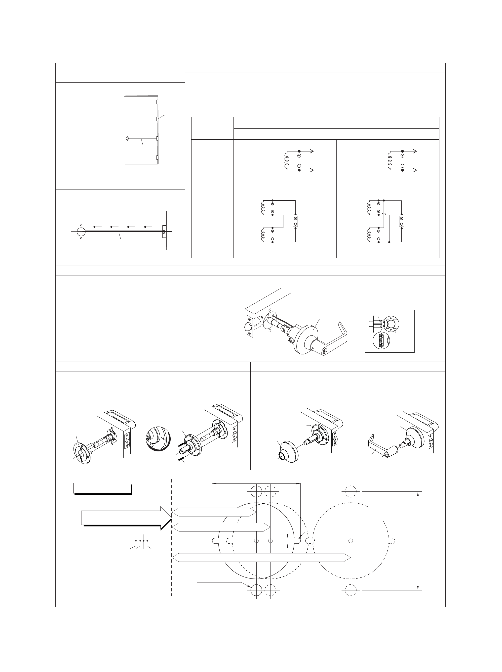
TEMPLATE
MARK CENTER OF
2-1/8"(54mm)
HOLE ON DOOR FACE
2-15/32"(62.7mm)
5/32"(4mm)
2-3/4" (70mm) BACKSET
2-3/8" (60mm) BACKSET
5" (127mm) BACKSET
FOLD HERE ON DOOR EDGE
(FOR METAL DOOR ONLY)
NOTE
DO NOT MAKE THE HOLES FOR
LOCKS IF REMOVING OUTSIDE
SECURING STUDS (THRU-BOLT)
a. Install inside mounting plate to lock body.
b. Press inside rose liner onto mounting plate and
tighten mounting screws securely.
INSIDE
MOUNTING PLATE
a. b. a. b.
a. Be sure to install rose in recess of rose liner.
b. Depress lever catch with tool provided.
Push inside lever on completely until catch engages in lever.
Confirm lever is secured.
12. INSTALL INSIDE ROSE AND LEVER
11. INSTALL INSIDE MOUNTING PLATE AND ROSE LINER
10. INSTALL OUTSIDE LEVER ASSEMBLY
Install outside lever assembly on the door.
Make sure tail of latch is engaging with retractor correctly ( .per illustration)
LATCH
LOCK
BODY
ASSEMBLY
CONDITION
Structure
of the Coils
Wire
Connection
Series Connection Parallel Connection
Temperature 20°C
Resistance Tolerance +/- 10%
DC24V 80Ω;0.3 Amp (+/- 10%) DC12V 20Ω;0.6 Amp (+/- 10%)
Red
Blue
41 Ohm Black
White
41 Ohm
Red
Blue
Black
White
DC24V
Red
Blue
Black
White
DC12V
For 24V application join Blue and Black wires, then connect Red to positive and White to negative on incoming power supply.
For DC12V application join Red and Black then connect both to positive, junction White and Blue then connect both to negative on the
incoming power supply.
DC
a. Connect the wire to 4 wire harnesses exiting the cylindrical lock chassis. (shown in the illustration below)
b. The wire and 4 wire harnesses must be joined firmly.
c. Make sure the bare wires are covered with insulating material.
A 3/8" wire raceway, from hinge to the door prep, must be
pre-installed inside the door.
7. MAKE SURE THE DOOR IS
CORRECTLY PREPPED
8. RUN THE WIRE THROUGH THE
RACEWAY
OUTSIDE LEVER ASSEMBLY
9. WIRE CONNECTION
Direct the wire through the raceway, from hinge to the
door prep, and pull the wire out of the door hole.
HINGE
3/8" WIRE
RACEWAY
3/8" WIRE RACEWAY
The wires must not be crimped or pinched by the door prep, or must not be exposed outside the door prep.
At the hinge end, carefully pull the wires out of the raceway and connect it to the power supply.


