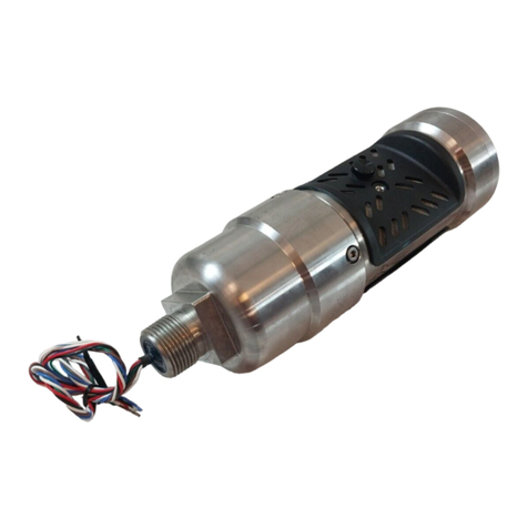
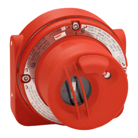
General Monitors FL4000H User manual

The information and technical data disclosed in
this document may be used and disseminated
only for the purposes and to the extent
specifically authorized in writing by General
Monitors.
Instruction Manual 7-16
General Monitors reserves the right to change
published specifications and designs without
prior notice.
MANFL4000NH
Part No. MANFL4000NH
Revision N/7-16
MODEL FL4000H
Multi-Spectral Infrared
Flame Detector

ii
Model FL4000H
This page intentionally left blank

iii
Model FL4000H
Table of Contents
MODEL FL4000H..............................................................................................................................1
MULTI-SPECTRAL INFRARED...................................................................................................1
FLAME DETECTOR.....................................................................................................................1
TABLE OF FIGURES...................................................................................................................V
TABLE OF TABLES....................................................................................................................VI
QUICK START GUIDE...............................................................................................................VII
Mounting and Wiring the Detector ........................................................................................................ vii
Applying Power to the Detector ............................................................................................................. ix
Testing the Detector Using a Test Lamp ................................................................................................x
ABOUT THIS MANUAL ...............................................................................................................X
Format Conventions................................................................................................................................x
Other Sources of Help.............................................................................................................................x
1.0BEFORE INSTALLATION....................................................................................................11
1.1System Integrity Verification ....................................................................................................11
1.2Commissioning Safety Systems ..............................................................................................11
1.3Special Warnings .....................................................................................................................11
1.4Glossary of Terms....................................................................................................................12
2.0PRODUCT OVERVIEW........................................................................................................14
2.1General Description .................................................................................................................14
2.2Features and Benefits ..............................................................................................................14
2.3Applications..............................................................................................................................15
2.4Principle of Operation...............................................................................................................15
3.0INSTALLATION....................................................................................................................21
3.1Unpacking the Equipment........................................................................................................21
3.2Required Tools.........................................................................................................................21
3.3Detector Location Guidelines...................................................................................................22
3.4Field Wiring Procedure ............................................................................................................26
3.5Detector Mounting and Installation ..........................................................................................27
3.6Terminal Connections ..............................................................................................................29
3.7Switch Selectable Options .......................................................................................................36
3.8Powering of the FL4000H ........................................................................................................38
3.9Power up Grounding of the Test and Relay Reset Lines.........................................................38
4.0MODBUS INTERFACE ........................................................................................................39
4.1Introduction ..............................................................................................................................39
4.2Communication Slave Address................................................................................................39

iv
Model FL4000H
4.3Baud Rate ................................................................................................................................39
4.4Data Format .............................................................................................................................39
4.5Supported Function Codes ......................................................................................................40
4.6Modbus Read Status Protocol (Query / Response).................................................................40
4.7Modbus Write Command Protocol (Query / Response) ..........................................................41
4.8Exception Responses and Exception Codes...........................................................................41
4.9Command Register Locations..................................................................................................43
4.10Command Register Details ......................................................................................................47
5.0MAINTENANCE ...................................................................................................................58
5.1General Maintenance...............................................................................................................58
5.2Cleaning the Sapphire Window................................................................................................58
5.3Sensitivity Check......................................................................................................................59
5.4Storage.....................................................................................................................................59
6.0TROUBLESHOOTING..........................................................................................................60
6.1Troubleshooting Chart .............................................................................................................60
6.2Final Assembly.........................................................................................................................61
7.0CUSTOMER SUPPORT.......................................................................................................62
7.1Other Sources of Help .............................................................................................................62
8.0APPENDIX............................................................................................................................63
8.1Warranty...................................................................................................................................63
8.2Specifications ...........................................................................................................................63
8.3Regulatory Information.............................................................................................................65
8.4Response to False Stimuli .......................................................................................................66
8.5Spare Parts and Accessories...................................................................................................67
9.0APPENDIX A........................................................................................................................70

v
Model FL4000H
Table of Figures
Figure 1: FL4000H Housing ..................................................................................................................................vii
Figure 2: Mounting Instruction .............................................................................................................................. viii
Figure 3: Wall Mounting Assembly....................................................................................................................... viii
Figure 4: Bracket Assembly....................................................................................................................................ix
Figure 5: Field Terminations Showing Wiring for Fire Alarm Systems...................................................................ix
Figure 6: FL4000H Front View ............................................................................................................................. 14
Figure 7: Test Lamp Flashing Option (Auto-detection) ........................................................................................ 19
Figure 8: Grounding of Test Wire or Modbus Command Options........................................................................ 20
Figure 9: Horizontal FOV – n-Heptane – High Sensitivity. ................................................................................... 23
Figure 10: Horizontal FOV – n-Heptane – Medium Sensitivity............................................................................. 23
Figure 11: Horizontal FOV – n-Heptane – Low Sensitivity................................................................................... 24
Figure 12: Vertical FOV – n-Heptane – High Sensitivity. ..................................................................................... 24
Figure 13: Vertical FOV – n-Heptane – Medium Sensitivity................................................................................. 25
Figure 14: Vertical FOV – n-Heptane – Low Sensitivity. ...................................................................................... 25
Figure 15: FL4000H Housing ............................................................................................................................... 26
Figure 16: Detector Mounting and Installation...................................................................................................... 28
Figure 17: Dimensional Drawing .......................................................................................................................... 29
Figure 18: Wire-Strip Lengths............................................................................................................................... 29
Figure 19: Base Housing and Terminal Blocks .................................................................................................... 30
Figure 20: Terminal Connections ......................................................................................................................... 31
Figure 21: Relay Contacts .................................................................................................................................... 32
Figure 22: Wiring Diagram – Reset Relays, Test Mode, & Alarm Test ................................................................ 34
Figure 23: Dipswitch Location .............................................................................................................................. 37
Figure 24: Command Register ............................................................................................................................. 49
Figure 25: Optical Parts to Clean ......................................................................................................................... 58
Figure 26: FL4000H Cross-Section View ............................................................................................................. 61
Figure 27: Rain Guard Installation........................................................................................................................ 69
Figure 28: Functional Board Located Under TL105 Lamp Assembly .................................................................. 70

vi
Model FL4000H
Table of Tables
Table 1: Glossary of Terms .................................................................................................................................. 12
Table 2: Sample Industry Applications ................................................................................................................. 15
Table 3: LED sequence for each operating condition. ......................................................................................... 16
Table 4: Required Tools ....................................................................................................................................... 21
Table 5: Maximum Specified Fields of View at High Sensitivity........................................................................... 22
Table 6: Sensitivity Settings for n-Heptane .......................................................................................................... 25
Table 7: Terminal Block Connections................................................................................................................... 30
Table 8: Alarm Relay Terminals ........................................................................................................................... 31
Table 9: Warning Relay Terminals ....................................................................................................................... 32
Table 10: Fault Relay Terminals........................................................................................................................... 33
Table 11: Alarm Reset Terminal........................................................................................................................... 33
Table 12: Test Mode Terminal.............................................................................................................................. 33
Table 13: Alarm Test Terminals ........................................................................................................................... 34
Table 14: Analog Output Terminal........................................................................................................................ 34
Table 15: Analog Output Levels ........................................................................................................................... 35
Table 16: Maximum Cable Lengths for 250 Inputs........................................................................................... 35
Table 17: Power Terminals................................................................................................................................... 35
Table 18: Maximum Cable Lengths for +24 VDC................................................................................................. 35
Table 19: Modbus Terminals ................................................................................................................................ 36
Table 20: Chassis Ground Terminal..................................................................................................................... 36
Table 21: Dipswitch Options................................................................................................................................. 37
Table 22: Selectable Baud Rates ......................................................................................................................... 39
Table 23: Selectable Data Formats...................................................................................................................... 39
Table 24: Modbus Read Register(s) Request ...................................................................................................... 40
Table 25: Modbus Read Register(s) Response ................................................................................................... 40
Table 26: Modbus Write Register Request .......................................................................................................... 41
Table 27: Modbus Write Register Response........................................................................................................ 41
Table 28: Exception Response............................................................................................................................. 42
Table 29: Exception Codes .................................................................................................................................. 42
Table 30: Command Register Locations .............................................................................................................. 43
Table 31: Status Mode Values ............................................................................................................................. 47
Table 32: Modbus Error Codes ............................................................................................................................ 48
Table 33: Com1 Baud Rate .................................................................................................................................. 50
Table 34: Selectable Data Formats...................................................................................................................... 50
Table 35: Event Log Clock Time Format.............................................................................................................. 54
Table 36: Troubleshooting Chart .......................................................................................................................... 60
Table 37: Locations .............................................................................................................................................. 62
Table 38: False Alarm Immunity at High Sensitivity ............................................................................................. 66
Table 39: Flame Response in the Presence of False Alarm Sources (High Sensitivity) ..................................... 67
Table 40: List of Spare Parts ................................................................................................................................ 68

vii
Model FL4000H
Quick Start Guide
Mounting and Wiring the Detector
Pay special attention to the conduit seal entry (Canadian Electrical Code Handbook Part 1,
Section 18-154). Mount the detector by using the swivel mount or mounting bracket hardware.
The following procedure should be used in conjunction with the housing diagram below to
disassemble the Optical Housing Assy for wiring:
Figure 1: FL4000H Housing
1. Loosen the captive screws (A) located on the Optical Housing Assy.
2. Pull the Optical Housing Assy from the Base Housing Assy to separate, gently rock from
side to side if necessary to loosen the connector’s grip.
3. Wire the unit to the site-wiring following the connection diagram shown in Figure 5.
4. Reassemble the unit using steps 1 thru 2 in reverse.
CAUTION: Do not unscrew the field wiring board from the base housing assembly for wiring.
A

viii
Model FL4000H
Figure 2: Mounting Instruction
Figure 3: Wall Mounting Assembly

ix
Model FL4000H
Figure 4: Bracket Assembly
Figure 5: Field Terminations Showing Wiring for Fire Alarm Systems1
Applying Power to the Detector
Two light emitting diodes (LED’s) are visible through the window. Immediately upon powering
up the detector, both LED’s will start blinking alternately for 15 seconds. The unit will then enter
the “Ready” mode. During the “Ready" mode, the green LED will flash off 0.5 seconds every 5
seconds.
1Recommended by Underwriters’ Laboratories of Canada.

x
Model FL4000H
Testing the Detector Using a Test Lamp
Test the integrity of your system by using a Test Lamp. The original configuration (i.e.
sensitivity and relay options) can be changed by referring to Section 3.7 , and then changing
the dipswitch settings located on the bottom of the power board (SW1).
The instrument is now ready to operate. Please consult the Test Lamp manual for more
information on the instrument’s many features. If you have any problems in the set-up or testing
of the detector, please refer to the “Trouble Shooting Section”, or call the factory direct.
About This Manual
This manual provides instructions for installing, operating, and maintaining the General
Monitors (GM) FL4000H Flame Detector. The intended audience includes installation
personnel, field service technicians, Modbus programmers, and other technical staff involved in
installing and using an FL4000H.
Format Conventions
Several format conventions are used throughout this manual for Notes, Cautions, Warnings,
User Menus, and Modbus notations. These conventions are described below.
Notes, Cautions, and Warnings
NOTE: Notes provide supplementary details such as exception conditions, alternate methods
for a task, time saving tips, and references to related information.
CAUTION: These notices describe precautions to prevent hazardous conditions that may
damage the equipment.
WARNING: These notices describe precautions to prevent hazardous conditions that may
cause injury to people working with the equipment.
Modbus Register Formats
Hexadecimal numbers are used in Modbus registers and are indicated by the addition of either
“0x” in front of a number or “h” after the number (example: 0x000E or 000Eh, respectively).
Other Sources of Help
General Monitors provides extensive documentation, white papers, and product literature for
the company’s complete line of safety products, many of which can be used in combination with
the FL4000H. Many of these documents are available online at
http://www.MSAsafety.com/detection.
Contacting Customer Support
For additional product information not contained in this manual, please contact General
Monitors Customer Support. Refer to Section 7.0 for contact information.

11
Model FL4000H
1.0 Before Installation
1.1 System Integrity Verification
General Monitors’ mission is to benefit society by providing safety solutions through industry
leading products, services, and systems that save lives and protect capital resources from the
dangers of hazardous flames, gases, and vapors.
General Monitors’ safety products should be handled carefully and installed, calibrated, and
maintained in accordance with the individual product instruction manuals. To ensure operation at
optimum performance, General Monitors recommends that prescribed maintenance procedures be
followed.
1.2 Commissioning Safety Systems
Before power up, verify wiring, terminal connections, and stability of the mountings for all essential
safety equipment including, but not limited to:
Power supplies
Control modules
Field detection devices
Signaling / output devices
Accessories connected to field and signaling devices
After the initial power up and any factory specified warm-up period of the safety system, verify that
all signal outputs, to and from the devices and modules, are within the manufacturer’s
specifications. Initial calibration / calibration checking / testing should be performed according to
the manufacturer’s recommendations and instructions.
Proper system operation should be verified by performing a full, functional test of all component
devices of the safety system, ensuring that the proper alarm levels occur. Fault / Malfunction circuit
operations should be verified.
1.3 Special Warnings
WARNING: Toxic, combustible, and flammable gases and vapors are dangerous. Extreme
caution should be used when these hazards are present.
CAUTION: Keep cover tight while circuits are alive.
CAUTION: Do not open when an explosive atmosphere is present.
Through engineering design, testing, manufacturing techniques, and rigid quality control, General
Monitors supplies the finest flame detection systems available. The user must recognize his
responsibility for maintaining the flame detection system in operational condition.
The FL4000H contains components that can be damaged by static electricity. In order to avoid
static electricity, special care must be taken when wiring the system to ensure that only the
connection points are touched.
The FL4000H is rated Explosion Proof (XP) for use in hazardous locations.
Conduit seals or suitably approved Ex d glands must be used to preserve the explosion proof
safety of the FL4000H and help prevent ingress of water or gas from the conduit systems. A
conduit seal must be installed within 18 inches of the enclosure per NEC regulations.

12
Model FL4000H
Silicone Room Temperature Vulcanization (RTV) is not an approved moisture barrier. If used,
damage to internal components will arise.
Damage to the FL4000H housing where any internal components or protective seals are broken,
compromises the safety and usability of the device. An FL4000H with a damaged or open housing
should not be used in a hazardous environment. Such damage includes fractures in the housing,
cracks in any internal components, or cracks in the protective seals.
1.4 Glossary of Terms
Table 1: Glossary of Terms
Term /
Abbreviation Definition
A Amps
AC Alternating Current
ANN Artificial Neural Network
AWG American Wire Gauge
Baud Rate The number of signal level changes per second in a line, regardless of
the information content of those signals
bps Bits per second
Cable Armor Cable having interlocked or corrugated armor where it is essential to
provide positive grounding of cable armor
Cable Screen Mesh surrounding a cable
COM DC Ground
COPM Continuous Optical Path Monitoring
CR Control Room
CRC Cycle Redundancy Check
DC Direct Current
DCS Distributed Control System
De-Energized To disconnect from a power source
DSP Digital Signal Processor
EEPROM Electrically Erasable Programmable Read-Only Memory
EMI Electromagnetic Interference
ENERGIZED To apply voltage or energy
FOV Field of View
FS Full Scale
GM General Monitors
HART Highway Addressable Remote Transducer-communication protocol
Hex Hexadecimal Number
I / O Input / Output
Instrument Earth Grounded using a grounding strap
Latching Refers to relays remaining in the “on” state even after the “on” condition
has been removed
LED Light Emitting Diode
LSB Least Significant Bit
mA Milli-Amps refers to 1/1000 of an Amp
Master Controls one or more devices or processes
Modbus Master-slave messaging structure
N/A Not Applicable
NC Normally Closed
NO Normally Open

13
Model FL4000H
Term /
Abbreviation Definition
Non-Latching Refers to relays being reset to the initial state after “on” condition has
been removed
NPT National Pipe Thread
OV Return Over voltage return
0VDC Power Supply Common Ground
Oxidation Combining with Oxygen
PCB Printed Circuit Board
PLC Programmable Logic Controller
ppm Parts per million
RFI Radio Frequency Interference
RMS Root-Mean-Square
ROM Read Only Memory
RTV Room Temperature Vulcanization
Safety Earth Grounded to the earth
Slave One or more devices or processes controlled by a master controller
SMT Surface Mount Technology
SPAN Value The programmed range of measurable parts per million
SPDT Single Pole, Double Throw
SPST Single Pole, Single Throw
TB Terminal Block
V Volts
VAC Volts Alternating Current
VDC Volts Direct Current
XP Explosion Proof

14
Model FL4000H
2.0 Product Overview
2.1 General Description
The General Monitors’ FL4000H is a Multi-
Spectral Infrared (MSIR) Flame Detector
(Figure 6). The FL4000H employs state-of-
the-art infrared (IR) detectors and a
sophisticated artificial neural network (ANN)
based signal processing to produce a system
that is highly immune to false alarms caused
by lightning, sunlight reflection, arc-welding,
hot objects, and other sources of radiation. In
addition, the FL4000H can see through most
smoky type fires such as diesel, rubber, etc.
The FL4000H is certified as explosion proof
for use in hazardous locations (Section 8.3.2).
It can also be used for general-purpose, non-
hazardous applications. Figure 6: FL4000H Front View
2.2 Features and Benefits
High False Alarm Immunity: Provides reliable flame detection performance by utilizing a
proprietary ANN processing algorithm to minimize false alarms. Please refer to Sec. 8.4 for more
details on the behavior of the instrument in the presence of false stimuli.
Wide Field of View (FOV): Encompasses a larger area of detection with uniform sensing and no
blind spots.
Modular Design: Results in low maintenance and reduced total cost of ownership.
Compact Unitized Design: Enhances ease of installation and maintenance.
Continuous Optical Path Monitoring (COPM): Regularly monitors the optical path to ensure the
window is not dirty.
0-20 mA Analog Output: Transmits alarm and fault indication to a remote display, computer, or
other device such as an alarm, dispensing device, or master controller.
Dual Redundant Modbus RS-485 User Interface (Standard FL4000H Configuration):Provides
the capability to operate the FL4000H remotely, using 2 redundant channels. This interface allows
the user to remotely change the alarm and warning relay settings, clear selected faults, clear error
counters, change baud rates, and change formats for serial communication lines.
HART Protocol2(Optional HART Configuration): The HART equipped FL4000H supports the
HART communication protocol version 6. Using this protocol, users can transmit diagnostics,
settings, and other device status information that improves the efficiency of remote communication.
NOTE: FL4000H HART should not be used with General Monitors TA402A and FL802
Controllers.
2HART® is a registered trademark of the HART Communication Foundation

15
Model FL4000H
2.3 Applications
The FL4000H provides flame detection for a wide range of applications, including, but not limited to
the following:
Table 2: Sample Industry Applications
Industries Sample Applications
Oil and Gas On and Offshore Platforms
Gas Pipelines Compressor Buildings
Airports / Military Airplane Hangars
Gas Turbines Turbine Enclosures
Chemical Plants Process Buildings
Loading Terminals Trucking On / Off Loading Areas
Petrochemical Process Areas
Refineries Tank Farms and Process Areas
2.4 Principle of Operation
The FL4000H is a discriminating multi-spectral infrared detector, which makes use of infrared
sensors for different IR wavelengths and characteristics. This combination provides a flame
detection system, which is highly immune to false alarms.
The ANN network classifies the output signals from the detector as either fire or no-fire. The unit
then produces the following output signals:
0 to 20 mA signal (3.5 or 1.25 to 20 mA with optional HART protocol)
Immediate WARN relay contacts
Time delayed ALARM relay contacts
FAULT relay contacts
RS-485 Modbus output
Redundant RS-485 Modbus output
(Refer to Section 3.0 and Section 4.0 for more information on detector outputs.)
2.4.1 Visual Indicators
Two light emitting diodes (LEDs) are visible on the front detector window. These LEDs provide a
visual indication that corresponds with the detector’s outputs. The following LED flashing
sequences indicate various operating conditions:

16
Model FL4000H
Table 3: LED sequence for each operating condition.
# State Red Green Notes
1 Power up 0.5 sec On 0.5 sec On Alternating for 15 seconds
2 Ready Off 5 sec On
0.5 sec Off
3 Warning 0.5 sec On
0.5 sec Off Off
4 Alarm 0.2 sec On
0.2 sec Off Off
5 COPM Fault Off 0.5 sec On
0.5 sec Off
6 Low Voltage, Code or
Data, Checksum Fault Off 0.2 sec On
0.2 sec Off
7 Test Mode Activated Off 0.9 sec On
0.1sec Off
8 Test Mode Warning 0.5 sec On 0.5 sec On Alternating while detecting
Test Lamp
9 Test Mode Alarm 0.2 sec On 0.2 sec On Alternating while detecting
Test Lamp
2.4.2 Continuous Optical Path Monitoring - COPM Circuitry
A self-testing feature called Continuous Optical Path Monitoring (COPM) checks the optical path,
the detector(s), and the related electronic circuitry once every 2 minutes. If foreign material on the
front surface of the FL4000H blocks the COPM light from reaching the detector(s) for four minutes,
the unit will indicate FAULT. The optical FAULT outputs are a 2.0 mA (3.5 mA with HART and
small HART current disabled) signal, de-energizing of the FAULT relay, and Modbus (RS-485)
output signal. After a COPM FAULT, a COPM check is performed every twenty seconds. The
COPM will resume a once per 2-minute check only after the obstruction is removed.
CAUTION: Dirty or partially blocked windows can significantly reduce the detector’s field of view
and detection distance.
NOTE: Because the optical path is checked once every 2 minutes and requires two check failures
to produce a FAULT, it may take up to 4 minutes for the unit to detect an obstruction.
2.4.3 Test Mode Initiation
NOTE: The FL4000H will not detect a flame while in Test Mode.
The FL4000H has the ability to initiate a special Test Mode, which enables the user to test the
response of the unit without the use of a flame source. Once the Test Mode has been activated,
the unit will not detect a flame, but rather, responds to GM’s Test Lamp as a simulated flame
source.
There are four options for enabling Test Mode on the FL4000H:
1. Flashing of the Test Lamp
2. Momentary grounding of test wire3
3. Modbus command
4. HART command (available in HART configuration only)
3Underwriters’ Laboratories of Canada (ULC) does not sanction the grounding of test wire as an approach for enabling Test Mode. For ULC-
approved systems, only Test Lamp and HART and Modbus commands may be used.

17
Model FL4000H
Each time the Test Mode is activated and the Test Lamp is successfully detected, regardless of
which option is used, the FL4000H maintains a timestamp of the test. This timestamp is available
to the user via Modbus registers 0x6A, 0x6B, and 0x6C.
2.4.3.1 Test Mode Initiation via Test Lamp
NOTE: The Test Lamp sequence is depicted in Figure 7.
When the unit is in Operational Mode, the FL4000H recognizes the Test Lamp as a trigger to
activate the Test Mode. Within 5-8 seconds of the Test Lamp flashing, the FL4000H will detect the
simulated flame source, drop the analog output to 1.5 mA (3.5 mA with HART and small HART
current disabled), and change the LED flashing to indicate “Test Mode Activated” shown in
sequence #7 of Table 3. The relay setting will remain at “Ready” during this operation.
Further continuous flashing of the Test Lamp in Test Mode enables the following sequence of
events:
After 2 seconds in Test Mode (Phase 2), the FL4000H indicates a Warning condition, by
setting the analog output to 16 mA, changing the LED flashing to indicate “Test Mode
Running” shown in sequence #8 (Table 3), and setting the relay to Warning State.
After a user-selectable time delay of 0-304seconds (Phase 3), the FL4000H displays an
Alarm condition by setting the analog output to 20 mA, and setting the relay to Alarm
State. The LED sequence changes to sequence #9 (Table 3) “Warning” mode.
After 4.25 minutes in Alarm mode (Phase 4), the unit will return to Ready Mode by
dropping the analog output to 4.3 mA, restoring the LED flashing to “Ready” shown in
sequence #2 (Table 3), and setting the relay to Ready State. The FL4000H has now
returned to flame detection status.
NOTE: After the test is initiated via the Test Lamp, all other commands are ignored until the Test
Mode is over. While in Test Mode, the unit will not detect flames. Interruption of the Test
Lamp flashing for more than 3 seconds will result in termination of the test sequence and a
return to Ready Mode (Phase 0).
If a relay is latched, it must be manually reset via the reset relays line or a Modbus
command. There is a 10 second restart delay. After the unit returns to Ready State from
Phase 4, the unit waits for 10 seconds before a subsequent Test Lamp transition back to
Phase 1.
2.4.3.2 Test Mode Initiation via Grounding of Test Wire or Modbus Command
NOTE: Both grounding of the test wire and Modbus command sequence are depicted in Figure 8.
Momentary grounding of a test wire or the Modbus test-mode-enable command causes the
FL4000H to enter Test Mode. Initiation of Test Mode is indicated by the analog output dropping to
1.5 mA (3.5 mA with HART and small HART current disabled) and LED flashing in sequence # 7
(Table 3). The Test Lamp is not needed to enable Test Mode. If the Test Lamp is not used in Test
Mode, the Test Mode times out in 3 minutes.
Flashing of the Test Lamp in the Test Mode enabled via test wire or Modbus results in the
following sequence of events:
4Time delay can be set through Modbus to any value between 0 and 30 seconds, and via dipswitch to 0, 8, 10, or
14 seconds.

18
Model FL4000H
After 5-8 seconds of the Test Lamp flashing in Phase 3, the FL4000H goes into Phase 4,
indicating 1.5 mA (3.5 mA with HART and small HART current disabled) at the analog
output, changing the LED flashing to indicate “Test Mode Running” shown in sequence #8
(Table 3)
After 4.25 minutes in Phase 4, the FL4000H returns to Ready Mode, indicating 4.3 mA at
the analog output, restoring the LED flashing to “Ready” shown in sequence #2 (Table 3).
NOTE: After the test is initiated via wire or Modbus; all other commands are ignored until the Test
Mode is over. While in Test Mode, the unit will not detect flames. Interruption of the Test
Lamp flashing for more than 3 seconds will result in termination of the test sequence and a
return to Ready Mode (Phase 0).

19
Model FL4000H
TEST
LAMP
FLASHING
READY
MODE
ANALOG
OUTPUT:
1.5 mA (3.5 mA
with HART)
LED FLASH
SEQUENCE:
Test Mode Active
(Sequence #7)
RELAY
SETTING:
Ready
ANALOG
OUTPUT:
16 mA
LED FLASH
SEQUENCE:
Test Mode Warning
(Sequence #8)
RELAY
SETTING:
Warning
ANALOG
OUTPUT:
20 mA
LED FLASH
SEQUENCE:
Test Mode Alarm
(Sequence #9)
RELAY
SETTING:
Alarm
ANALOG
OUTPUT:
4.3 mA
LED FLASH
SEQUENCE:
Ready Mode
RELAY
SETTING:
Ready
* USER SETTING VIA DIP SWITCH (0, 8, 10, OR 14 SEC) OR MODBUS (0 - 30 SEC)
** FACTORY PROGRAMMABLE
2 SEC. **
TEST LAMP CONTINUOUSLY FLASHING
0 - 30 SEC.*
4.25 MIN. ** 5 - 8 SEC.
PHASE 0
PHASE 1
PHASE 2
PHASE 3
PHASE 4
PHASE 0
TEST LAMP IS POINTED ON FL4000
Latching?***
YES
Latching?***
YES
IGNORED MISUSE CONDITIONS
- GROUND TEST WIRE
- HOLD TEST WIRE GROUNDED
- RESEND TEST MODE MODBUS COMMAND
-TEST LAMP FLASHING IN TL103 MODE FOR
TL104 OR IN SWITCH POSITIONS 1-3 and 5
FOR Tl105 TEST LAMP
*** IF RELAY IS LATCHED DURING THE TEST MODE, IT MUST BE MANUALLY RESET
VIA RESET RELAYS LINE OR MODBUS COMMAND
Figure 7: Test Lamp Flashing Option (Auto-detection)
H

20
Model FL4000H
GROUNDING OF TEST WIRE
OR
MODBUS COMMAND
READY
MODE
ANALOG
OUTPUT:
1.5 mA (3.5 mA
with HART)
LED FLASH
SEQUENCE:
Test Mode Active
(Sequence # 7)
RELAY
SETTING:
Ready
Test Lamp
FLASHING?
NO
LED FLASHING:
Test Mode Warning
(Sequence #8)
ANALOG
OUTPUT:
4.3 mA
LED FLASH
SEQUENCE:
Ready Mode
RELAY
SETTING:
Ready
3 MIN.* WAITING
TEST LAMP CONTINUOUSLY FLASHING TEST LAMP NOT FLASHING
5 - 8 SEC.4.25 MIN.* INSTANT
IN TEST MODE
* FACTORY PROGRAMMABLE
PHASE 0
PHASE 1
PHASE 2
YES
PHASE 3
PHASE 4
PHASE 0
ANALOG
OUTPUT:
1.5 mA (3.5 mA
with HART)
RELAY
SETTING:
Ready
IGNORED MISUSE CONDITIONS
- REPEAT GROUNDING OF TEST WIRE
- HOLD TEST WIRE GROUNDED
- RESEND TEST MODE MODBUS COMMAND
- TEST LAMP FLASHING IN TL103 MODE FOR TL104
OR IN SWITCH POSITIONS 1-3 and 5 FOR Tl105
TEST LAMP
LED FLASHING:
Test Mode Alarm
(Sequence #9)
Figure 8: Grounding of Test Wire or Modbus Command Options
Table of contents
Other General Monitors Security Sensor manuals

General Monitors
General Monitors FL3112 User manual

General Monitors
General Monitors TS4000 User manual

General Monitors
General Monitors FL4000 User manual

General Monitors
General Monitors IR5500 User manual

General Monitors
General Monitors FL3102 User manual

General Monitors
General Monitors IR5500 Operating instructions

General Monitors
General Monitors FL3100 User manual

General Monitors
General Monitors TL104 User manual

General Monitors
General Monitors FL3110 User manual

General Monitors
General Monitors IR400 User manual