manuals.online logo
Brands
  1. Home
  2. •
  3. Brands
  4. •
  5. Bentel Security
  6. •
  7. Security Sensor
  8. •
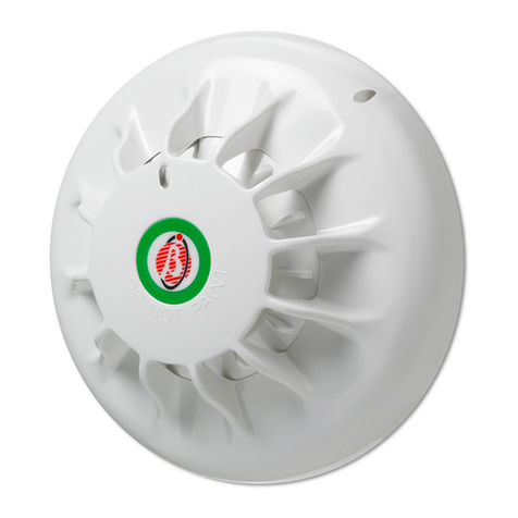
  9. Bentel Security FC450IB User manual

Bentel Security FC450IB User manual

ITALIANO
INTRODUZIONE
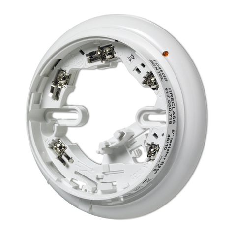
La serie di rilevatori FC400, normalmente, usano una comune Base
con Isolatore FC450IB per il fissaggio. Di seguito vengono date le in-
dicazioni per il montaggio ed il collegamento della Base con Isolatore.
FISSAGGIO DELLA BASE RILEVATORE
La base può essere fissata:
Øad una scatola da incasso Inglese (passo dei fori di fissaggio
50 mm) o Europea (passo dei fori di fissaggio 70 mm);
Øad una scatola di montaggio europea FC450EMB;
Ødirettamente a soffitto.
POSIZIONAMENTO DEL RILEVATORE
Il posizionamento del rilevatore dovrebbe essere definito nella fase di
progettazione del sistema in conformità alle specifiche del progetto. Le
basi del rilevatore devono essere montate in conformità con questo
progetto. Se si verificano problemi, indicare il riferimento del progettista.
La base del rilevatore non è necessario che sia allineata perchè il LED
del rilevatore risulta visibile a 360°.Tuttavia è necessario che l'indicato-
re di corto circuito sia visibile per l'individuazione del guasto.
FISSAGGIO DELLA BASE DEL RILEVATORE
nALLA SCATOLA DI CONNESSIONE
La base del rilevatore và assicurata direttamente alla scatola di connes-
sione con due viti testa piana d'acciaio M4, zincate o passivate. La
sede di fissaggio permette il montaggio di un'adeguata scatola ad in-
casso B.E.S.A. con passo dei fori di fissaggio da 50 mm o una scatola
da incasso Europea con passo dei fori di fissaggio da 70mm. Per facili-
ENGLISH
INTRODUCTION
The FC400 Series Detectors, as supplied, use a common
FC450IB Isolator Base assembly. Guidance on mounting and wir-
ing a FC450IB Isolator Base is given below.
FIXING THE DECTOR BASE
The base may be fixed directly to:
ØBritish (fixing centres 50mm) or European (fixing centres
70mm) conduit box;
ØFC450EMB Euro Mounting Box;
ØDirectly to the ceiling.
DETECTOR LOCATION
The location of each detector should have been determined at the
system design stage in accordance with the site plan. The detec-
tor bases must be mounted in accordance with this plan. If prob-
lems arise then reference to the system designer must be made.
The detector base does not need aligning as the detector LED is
visible through 360°. However, the short circuit indicator needs to
be visible for fault location.
FIXING THE DETECTOR BASE
nTO A CONDUIT BOX
The detector base is to be secured directly to the conduit box with
two M4 pan head steel screws, zinc plated and passivated. The
fixing slot allows the mounting to be fitted to both B.E.S.A. conduit
boxes having fitting points at 50mm centres and European conduit
boxes with fitting points at 70mm centres. For ease of fixing, there
POSIZIONAMENTO FORI PER VITI
SCREW LOCATING HOLES
FIG.1Dimensioni fissaggio per Base Rilevatore
Fixing Dimensions for Detector Base
FC450IB
®
ISO 14001
9191.BNT2
ISO 14001
IT-52588
ISO 9001
9105.BNT1
ISO 9001
IT-52587
BASE CON ISOLATORE
ISOLATOR BASE
ISTISBL3FC450IB 0.0 251007
INDICATORE DI CORTO CIRCUITO
SHORT CIRCUIT INDICATOR
CHIAVE DI BLOCCAGGIO
LOCKING KEY
PERNO PER IL PARCHEGGIO TEMPORANEO
TEMPORARY PARK
RIFERIMENTO RIALZATO
RAISED RIB
SEDE CHIAVE DI BLOCCAGGIO
LOCKING KEY SLOT
FIG. 2Base con Isolatore FC450IB *Brevettato
FC450IB Isolator Base *Patented
are enlarged holes on the fixing slots, which allows the first fixing
screw to be inserted loosely, the base is then fitted to the screw.
nTO OTHER SURFACES
The detector base is to be secured with two No. 8 x 1 inch pan
head steel screws zinc plated and passivated or equivalent at the
fixing centres shown in Fig. 1.The surface chosen for the mounting
should be flat over the area of the base to ensure a stable fixing.
nFC450EMB EURO MOUNTING BOX
The European Mounting Box (Fig. 4) is designed to be used with
the FC400 Series detectors in EC countries using 18mm and
21mm cable breakouts.The housing is secured with two No. 8 x 1
inch countersunk zinc plated and passivated steel screws (or
equivalent).The surface chosen for the mounting should be flat
over the area of the underside of the housing to ensure a stable fix-
ing and strong enough to take the weight of the mounting,detector
base and sensor.
tare l'installazione ci sono dei fori più larghi sulle aperture di fissaggio,
questo consente che la prima vite di fissaggio sia inserita senza blocca-
re, la base và fissata poi con la vite.
nAD ALTRE SUPERFICI
La base del rilevatore và assicurata ai fissaggi indicati in Fig.1 con
due viti testa piana in acciaio zincato o passivato da No. 8 x 1 polli-
ce o equivalenti. La zona scelta per il montaggio dovrebbe avere
una superficie piana per assicurare alla base un appoggio stabile.
nFC450EMB SCATOLA DI MONTAGGIO EUROPEA
La scatola di montaggio Europea (Fig.4) è progettata per l'uso con
la serie di rilevatori FC400 nei paesi della CE usando passacavi
da 18 mm e 21 mm. L'alloggiamento è assicurato con due viti testa
piana da No. 8 x 1 pollice in acciaio zincato o passivato da cm (o
equivalenti). La superficie scelta per il montaggio dovrebbe esse-
re piana sull'area e sotto l'alloggiamento per assicurare un appog-
gio stabile e abbastanza forte al peso del montaggio della base
del rilevatore e del sensore.
APERTURA LED
LED APERTURE
TAPPO APERTURA LED
LED APERTURE PLUG
DISPOSITIVO DI BLOCCAGGIO
LOCKING DEVICE
FORI POSIZIONAMENTO VITI
SCREW LOCATING HOLES
SEDE DISPOSITIVO DI BLOCCAGGIO
LOCKING DEVICE SLOT
FIG. 3Identificazione delle parti
Part identification
APERTURE DI FISSAGGIO
MOUNTING SLOTS
MORSETTO ACCESSORIO
PER LA BASE (BATs)
(di fabbrica, inserito solo
in una posizione)
BASE ACCESSORY
TERMINAL (BATs)
(factory fitted in
one position only)
NOTA: ULTERIORI MORSETTI POSSONO ESSERE ORDINATI IN BASE ALLE NECESSITÀ
NOTE: EXTRA BATs MAY BE ORDERED TO PROVIDE ADDITIONAL CABLE TERMINALS
FIG. 4Scatola di montaggio europea FC450EMB
FC450EMB Euro mounting box
5B 5B
5B
Schema di Collegamento Semplificato FIG. 5Simplified Circuit Diagram
COLLEGAMENTO DELLA BASE DEL RILEVATORE
La base del rilevatore và collegata come mostrato in Fig.5. Si sug-
gerisce di collegare al massimo due cavi da 1,5 mm2ad ogni ter-
minale. Adattatori sono forniti insieme alle flange esterne per il
montaggio del cavo a vista. Se specificato deve essere collegato il
LED remoto. Non stringere eccessivamente le viti dei terminali
quando si connette la base al collegamento loop.
nVERIFICA DEI COLLEGAMENTI LOOP
!ATTENZIONE: NON USARE UN VOLTMETRO ALTA
TENSIONE CON LE BASI CON MODULO ISOLATORE
COLLEGATE.
La base con modulo isolatore non è progettata per lavorare con ten-
sione di linea superiore a quella specificata di 40 Vdc. Ciò significa
che il test di continuità del loop con le Basi con Modulo Isolatore colle-
gate deve essere effettuato usando una tensione compresa tra 20-40
Vdc. Alcuni voltmetri convenzionali per la misura della resistenza uti-
lizzano bassa tensione, quindi, il seguente metodo può essere impie-
gato per confermare l’integrità del loop.Un alimentatore capace di
fornire una tensione di 30-40 Vdc con una corrente di 300-600 mA và
collegato ad una estremità del loop (rispettando le polarità). Un
voltmetro và collegato all'altra estremità del loop o lungo la linea stes-
sa per la verifica del collegamento fino a quel punto. Se non c'è ten-
sione sui punti misurati questo può essere dovuto a:
1) Loop circuito aperto - collegamenti incompleti sulla parte del loop.
2) Polarità non corretta - La base con modulo isolatore FC450IB
sembra in corto circuito se non è collegata rispettando le polarità.
3) Loop in corto circuito - Se questo si verifica tra due basi con modulo
isolatore FC450IB, quella sezione di linea si isola apparendo così
come circuito aperto. Se questo avviene tra l'alimentazione e la pri-
ma base con isolatore FC450IB, l'uscita dell'alimentazione passa
ad un valore basso a causa del limite di corrente interno.
nIDENTIFICAZIONE DEI CONNETTORI
La base con modulo isolatore FC450IB possiede cinque terminali:
RConnessione LED remoto
LNon connettere
L1 +ve IN/OUT
L2 -ve OUT
M-ve IN
nFISSAGGIO DEL DISPOSITIVO DI BLOCCO
Vedere Fig.2 e Fig.6. Per inserire la chiavetta di bloccaggio, stac-
carla dal corpo plastico della base. Per fissare il dispositivo di bloc-
co orientarlo e poi inserirlo come mostrato in Fig. 3.
nFISSAGGIO/RIMOZIONE DEL RILEVATORE.
1) Attaccare l'etichetta con il numero d'indirizzo sulla linguetta del
rilevatore.
2) Fissare la linguetta del rilevatore come mostrato in Fig.7.
3) Appoggiare il rilevatore sopra la base, girare poi il rilevatore in senso
orario fino a che non è completamente posizionato (la nervatura
rialzata sulla base e sul rilevatore devono essere allineate).
DETECTOR BASE WIRING
The detector base is to be wired as shown in Fig. 5. It is recom-
mended that a maximum of two 1.5mm2cables are connected at any
one terminal. A remote LED should be wired if specified. Breakouts are
provided at the outer flanges for surface cable mounting.Take care not
overtighten the terminal screws when connecting the base to the loop
wiring.
nVERIFYING LOOP WIRING
!WARNING: DO NOT MEGGER LOOP WIRING WITH LINE
ISOLATOR BASES CONNECTED.
The Line Isolator Base is not designed to work with line voltages
above the specified maximum 40V dc. This means that continu-
ity testing of the loop wiring with Line Isolator Bases connected
must be done using a voltage between 20-40V dc. The resis-
tance measurement range on conventional voltmeters use low
voltage only, therefore, the following method can be employed to
confirm loop integrity.A power supply capable of providing 30 -
40V dc with a 300 to 600mA current limit is connected to one end
of the loop (in correct polarity). A voltmeter is connected to the
other end of the loop or any base along the loop to verify the wir-
ing up to that point. If there is no voltage out at any measured
point, this may be due to:
1) Loop Open Circuit - wiring incomplete to part of the loop.
2) Incorrect Polarity -FC450IB Isolator bases will appear as a
short circuit if they are wired with incorrect polarity.
3) Loop Short Circuit - If this occurs between two FC450IB Isola-
tor bases, it will isolate that section of the line, which will then
appear as an open circuit. If this occurs between the supply
and the first FC450IB Isolator Base, the supply output will go
low due to the internal current limit.
nCONNECTOR IDENTIFICATION
The FC450IB Isolator Base has five terminals:
RRemote LED connector
LNot connected
L1 +ve IN/OUT
L2 -ve OUT
M-ve IN
nFITTING OF LOCKING DEVICE
Figs. 2 and 6refer. To fit the locking key, break it off from the sprue
connecting it to the body moulding. Fit the locking device in the
orientation shown in Fig. 3 and push firmly in.
nFITTING/REMOVAL OF A DETECTOR
1) Stick the address number labels to the Address Flag and de-
tector.
2) Fit the Address Flag to the detector as shown in Fig. 7.
3) Place the detector onto the base and turn until it locates on the
base, then turn clockwise until fully located (the raised ribs of
the base and detector are aligned).
4) If the detector is removed, the Address Flag will remain with the
base, ensuring that detectors are not accidentally returned to
the wrong base.
5) When a locking key has been inserted into the base, the detec-
tor may only be removed by using a lock release tool to de-
press the locking pin.
6) The temporary park plunger is used to allow the detector to be
placed in a park position once mounted to the base. This al-
lows the detector to be turned anti clockwise past the location
position to break electrical contact with the base. This means
the cabling to the detector may be tested with the detector
mounted to the base.
nCOMMISSIONING
Commission the fitted detector as detailed in Installation/Commis-
sioning document.
ORDERING INFORMATION
FC450IB: 5" Isolator Base
FC450EMB: Euro Mounting Box
Base AccessoryTerminal (pack of 10)
RECYCLING INFORMATION
BENTEL SECURITY recommends that customers dispose of their
used equipments (panels, detectors, sirens, and other devices) in
an environmentally sound manner. Potential methods include re-
use of parts or whole products and recycling of products, compo-
nents, and/or materials.
For specific information see
www.bentelsecurity.com/en/environment.htm
WASTE ELECTRICAL AND ELECTRONIC EQUIPMENT
(WEEE) DIRECTIVE
In the European Union, this label indicates that this
product should NOT be disposed of with household
waste. It should be deposited at an appropriate facility
to enable recovery and recycling.
For specific information see
www.bentelsecurity.com/en/environment.htm
BENTEL SECURITY s.r.l. reserves the right to change the techni-
cal specifications of this product without prior notice.
4) Se il rilevatore viene rimosso, la linguetta dell'indirizzo rimane
con la base, assicurarsi che i rilevatori non vengano casual-
mente reinseriti sulle basi errate.
5) Quando la chiave di blocco è inserita sulla base il rilevatore
può essere rimosso soltando usando un attrezzo per la rimo-
zione della chiave di blocco che preme il perno di bloccaggio.
6) Il perno per il parcheggio temporaneo è usato per far si che il ri-
levatore sia disposto in posizione di parcheggio una volta mon-
tato sulla base. Questo permette che il rilevatore, girato in
senso antiorario, cambi posizione interrompendo il contatto
elettrico con la base. Questo significa che il cablaggio del rile-
vatore può essere testato con il rilevatore montato sulla base.
nMESSA IN SERVIZIO
Sul documento di installazione/messa in servizio sono riportati i
dettagli del rilevatore.
INFORMAZIONI PER L'ORDINE
FC450IB: Base con Isolatore 5''
FC450EMB: Scatola di montaggio euro
Terminali accessori per la Base (confezione da 10 pz )
INFORMAZIONI SUL RICICLAGGIO
BENTEL SECURITY consiglia ai clienti di smaltire i dispositivi
usati (centrali, rilevatori, sirene, accessori elettronici, ecc.) nel ri-
spetto dell'ambiente. Metodi potenziali comprendono il riutilizzo di
parti o di prodotti interi e il riciclaggio di prodotti, componenti e/o
materiali.
Per maggiori informazioni visitare
www.bentelsecurity.com/it/ambiente.htm
DIRETTIVA RIFIUTI DI APPARECCHIATURE ELETTRICHE
ED ELETTRONICHE (RAEE - WEEE)
Nell'Unione Europea, questa etichetta indica che que-
sto prodotto NON deve essere smaltito insieme ai ri-
fiuti domestici. Deve essere depositato in un impianto
adeguato che sia in grado di eseguire operazioni di re-
cupero e riciclaggio.
Per maggiori informazioni visitare
www.bentelsecurity.com/it/ambiente.htm
BENTEL SECURITY s.r.l. si riserva il diritto di modificare le speci-
fiche tecniche di questo prodotto senza preavviso.
FIG. 6Inserimento del Dispositivo di Bloccaggio
Fitting of Locking Device
INCAVI DI BLOCCAGGIO
RETAINING DEPRESSIONS
RIENTRANZA DI MONTAGGIO
MOUNTING RECESS
PARTE SAGOMATA A ´D`
´D` SHAPED PART
CANALE SAGOMATO A ´U`
´U` SHAPED CHANNEL
SPORGENZE DI BLOCCAGGIO
RETAINING PIMPLES
FIG. 7Inserimento della Linguetta Indirizzo
Fitting Address Flag

Other Bentel Security Security Sensor manuals

Bentel Security BW-MCN User manual

Bentel Security

Bentel Security BW-MCN User manual

Bentel Security FC450IB User manual

Bentel Security

Bentel Security FC450IB User manual

Bentel Security IR 360 User manual

Bentel Security

Bentel Security IR 360 User manual

Bentel Security RAY60 User manual

Bentel Security

Bentel Security RAY60 User manual

Bentel Security BL151 User manual

Bentel Security

Bentel Security BL151 User manual

Bentel Security ZT100H User manual

Bentel Security

Bentel Security ZT100H User manual

Bentel Security FC400H User manual

Bentel Security

Bentel Security FC400H User manual

Bentel Security DT800 User manual

Bentel Security

Bentel Security DT800 User manual

Bentel Security AMC10 User manual

Bentel Security

Bentel Security AMC10 User manual

Bentel Security RAY60-S User manual

Bentel Security

Bentel Security RAY60-S User manual

Bentel Security DT800 User manual

Bentel Security

Bentel Security DT800 User manual

Bentel Security BMD503 User manual

Bentel Security

Bentel Security BMD503 User manual

Bentel Security Visus99 User manual

Bentel Security

Bentel Security Visus99 User manual

Popular Security Sensor manuals by other brands

Fetal Doppler i100 Operation manual

Fetal Doppler

Fetal Doppler i100 Operation manual

Tyco BLAZEMASTER CPVC manual

Tyco

Tyco BLAZEMASTER CPVC manual

Ryobi RP4300 Operator's manual

Ryobi

Ryobi RP4300 Operator's manual

Baumer UNDK 30U6103 quick start guide

Baumer

Baumer UNDK 30U6103 quick start guide

Tatsuta Electric Wire & Cable AD-AS-1AM instruction manual

Tatsuta Electric Wire & Cable

Tatsuta Electric Wire & Cable AD-AS-1AM instruction manual

Telefunken HVMM LICHT MAL 31550xTF Mounting instructions

Telefunken

Telefunken HVMM LICHT MAL 31550xTF Mounting instructions

sewerin Ex-Tec OD 4 operating instructions

sewerin

sewerin Ex-Tec OD 4 operating instructions

Coral MANTA user guide

Coral

Coral MANTA user guide

ITALIANA SENSORI 8028-ISR020 manual

ITALIANA SENSORI

ITALIANA SENSORI 8028-ISR020 manual

Reno A&E T-400 Series operating instructions

Reno A&E

Reno A&E T-400 Series operating instructions

Elkron FAP54 user manual

Elkron

Elkron FAP54 user manual

SCE SE230K quick start guide

SCE

SCE SE230K quick start guide

Samcon ExCam XPT Q6055 user manual

Samcon

Samcon ExCam XPT Q6055 user manual

SANJIANG JTF-GDM-936E Operation manual

SANJIANG

SANJIANG JTF-GDM-936E Operation manual

eufy Security T8450 quick start guide

eufy Security

eufy Security T8450 quick start guide

SUREN CDL-608R12 quick start guide

SUREN

SUREN CDL-608R12 quick start guide

Optex OA-AXIS I Operation manual

Optex

Optex OA-AXIS I Operation manual

Inovonics EN1245 installation instructions

Inovonics

Inovonics EN1245 installation instructions

manuals.online logo
manuals.online logoBrands
  • About & Mission
  • Contact us
  • Privacy Policy
  • Terms and Conditions

Copyright 2025 Manuals.Online. All Rights Reserved.