Jet-Set JM-3080™
USE CAUTION WHEN PRESSURE WASHING. WEAR
GOGGLES AND RUBBER GLOVES AND BOOTS. AN-
ALYZE ANGLE OF SPRAY AND ANTICIPATE AN-
GLE OF BACK SPLASH. DO NOT POINT SPRAY AT
ANYONE, INCLUDING YOURSELF. DO NOT PUT
YOUR HAND IN FRONT OF WATER SPRAY. IT CAN
PENETRATE THE SKIN AND CAUSE A NEED FOR
AMPUTATION. IT IS BEST TO START AT A 45°
ANGLE AT A 7 TO 10 FT. (2 TO 3M) DISTANCE FROM
OBJECT TO BE CLEANED. DIRECT SPRAY AT
CLOSE RANGE CAN BE POWERFUL ENOUGH TO
CAUSE DAMAGE.
The Spray Wand can be used to clean your truck or other applica-
tions. Caution: Never clean the machine with its own spray. Follow
the same procedures listed previously for safety, set-up, operation,
and maintenance. To operate the spray wand with your water jet,
disconnect to twist connect at the output valve. Then, connect the
spray wand hose, trigger and wand at the output valve. Turn on the
water supply, then squeeze the trigger to purge air from the system.
Continue to squeeze trigger as you turn on the machine.
Hold the high pressure spray nozzle approximately 6 –8 ft. from the
surface to be cleaned. When cleaning with a detergent, apply from
bottom up with an even left to right movement. Rinse from top down
with a similar motion. This will help reduce potential streaking. Always
apply soap to a dry surface. This will enhance penetration and deter-
gent cling and reduce dilution of detergent with an already wet sur-
face.
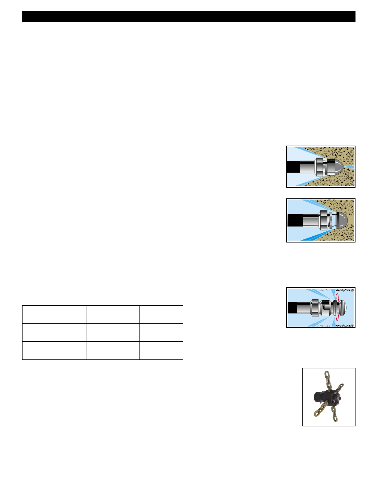
You may draw soap through the spray wand in conjunction with the
optional chemical injector. First set up the Chemical injector system
(see Chemical Injector). Then, simply turn the nozzle barrel on the
end of the wand counter-clockwise. As the spray pattern widens, more
of the detergent will be drawn through the wand. Turn the nozzle
clockwise to reduce the detergent flow and narrow the water spray
pattern to return to high pressure.
CHEMICAL INJECTOR –Cat # CMA-1
To use the chemical injector, disconnect the Twist Connect at the
output valve on the jet. Then thread the Chemical Injector on to it. The
Spray Wand then threads onto the free end of the Chemical Injector.
Do not attach Chemical Injector to the inlet side of the pump. Deter-
gents can damage pump.
To use the detergent injector, attach one end of the siphon hose to
the barbed fitting on the injector and put the filter end into the deter-
gent solution. Be sure the end of the hose is at the bottom of the con-
tainer or bucket. Some models have adjustable valves to control the
amount of detergent drawn through the hose.
MAINTENANCE
Regular inspection is the key to preventing breakdowns and prolong-
ing the life of the equipment. Follow this simple procedure religiously.
DAILY
Check INLET FILTER for debris before each use.
Check that the PUMP OIL LEVEL is within operating range on
dipstick or sight glass.
Check that the jet nozzles are not clogged or worn out.
WEEKLY
Check the pressure hose for wear and damage. Damaged hose
can be repaired at a local service dealer of by your equipment
dealer.
Pump Crankcase Oil Change: Service after the 1st month, or after
20 hours. Then service every year or 500 hours. Use SAE 30W Non-
Detergent Motor Oil to full mark on dipstick or to dot on sight glass.
Engine Maintenance: Check engine manual for specific maintenance
procedures.
7
ACCESSORIES
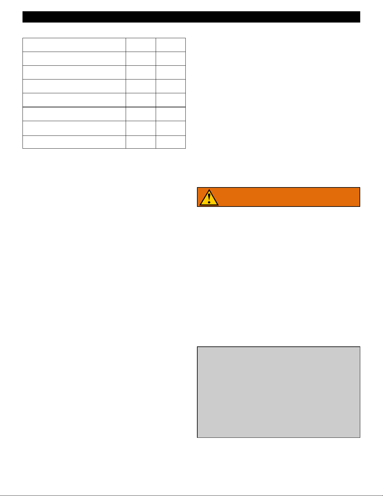
HANDY-REEL WITH FOOT PEDAL
- Cat # HM-200-W (OPTIONAL)
The Handy-Reel allows for remove applica-
tion of the jet. The jet can be positioned at
ground level, while the Handy-Reel can be
carried up on a roof to clear vents and
stacks. With the help of the Handy-Reel,
gas jets can be used for indoor applications
while the machine operates safely outside.
The Foot Pedal interrupts the flow of water between the pump and the
nozzle while leaving both hands free to guide the hose. Position the
Handy-Reel at the drain site. Connect the jet machine to the inlet on
the Foot Pedal. Select and attach nozzle to the hose on the reel. Put
the hose 2 to 3 ft. into the drain line. Follow the start-up procedures.
FOOT PEDAL ONLY - Cat # FM-1 (OPTIONAL)
The Foot Pedal can be used with any jet manufactured by General. It
interrupts the flow of water between the pump and the nozzle while
leaving both hands free to guide the hose. The pump will continue to
run in by-pass mode. Do not leave pump in by-pass for more than a
few minutes or the pump can be damaged. (See Pressure Unloader)
The Foot Pedal may be connected either at the machine or remotely
at the drain site. To use the foot pedal at the machine, remove the
hose going to the swivel on the hose reel and attach it to the inlet side
of the Foot Pedal. Then, connect the accessory hose (available in 6
ft., 25 ft., or 50 ft. lengths) between the outlet of the pedal and the
swivel on the hose reel. Some jet models may need the added length
of the accessory hose on the inlet side of the pedal.
For remote operation, pull the hose from the hose reel to the drain
site. Attach the hose to the inlet of the pedal. The pedal is designed
for 3/8” hose fittings. If using a 1/4” hose, use the AD-1 adapter, as
well. Then, attach the smaller hose (1/8” or 1/4”) to the outlet side of
the pedal. Use the smaller hose to clear the drain line.
SPRAY WAND -
Cat # SWA-3080