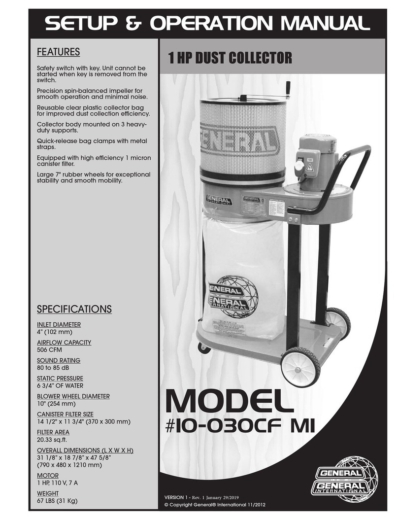
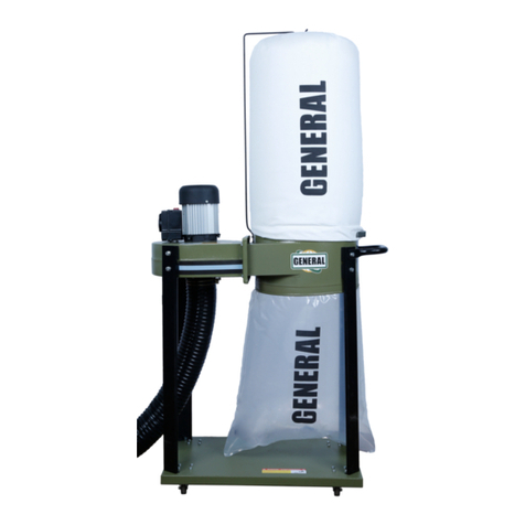
General 10-030 M1 Parts list manual

MANUEL D’INSTRUCTIONS ET D’ASSEMBLAGE
MODÈLE
#10-030 M1
CAPTEUR DE POU IÈRE 1 CV
CARACTÉRISTIQUES
Puissant moteur 1 CV, lubrifié à vie
pour un roulement silencieux et de
longue durée.
Interrupteur de sureté avec clé. L’unité
ne peut démarrer lorsque la clé n’est
pas insérée dans l’interrupteur.
Ventilateur à ailette balancé avec
précision pour un fonctionnement en
douceur et un minimum de bruit.
Sac de récupération réutilisable en
plastique transparent améliorant l'effi-
cacité de la récupération de pous-
sière.
Châssis du capteur monté sur 3 tiges
de support ultra-robustes.
Ceinture de métal avec attache à
ressort.
Muni de cartouches de filtration à
rendement élevé de un micron.
Larges roues de 7” en caoutchouc
permettant une meilleure stabilité et
un déplacement tout en douceur.
SPÉCIFICATIONS
DIAMÈTRE DE L'ENTRÉE
4” (102 mm)
CAPACITÉ D'ASPIRATION
506 Pi3/MIN.
NIVEAU SONORE
80-85 dB
PRESSION STATIQUE
6 3/4” d'eau
DIAMÈTRE DU VENTILATEUR
10" (254 mm)
DIMENSIONS DE LA CARTOUCHE
14 1/2" x 11 3/4" (370 x 300 mm)
SURFACE DE FILTRATION
20.33 Pi3
DIMENSIONS DE LA MACHINE
31 1/8” x 18 7/8” x 47 5/8”
(790 x 480 x 1210 mm)
MOTEUR
1 CV, 110 V, 7 A
POIDS
67 LBS (31 Kg) VERSION 1 - FÉVRIER 2012
© Copyright eneral® International 2012

SETUP & OPERATION MANUAL
VERSION 1 - FEBRUARY 2012
© Copyright eneral® International 2012
MODEL
#10-030 M1
1 HP DU T COLLECTOR
FEATURES
Powerful 1 HP motor features sealed
bearing and shaft for quiet, long-
lasting operation.
Safety switch with key. Unit cannot be
started when key is removed from the
switch.
Precision spin-balanced impeller for
smooth operation and minimal noise.
Reusable clear plastic collector bag
for improved dust collection efficien-
cy.
Collector body mounted on 3 heavy-
duty supports.
Quick-release bag clamps with metal
straps.
Equipped with high efficiency 1
micron canister filter.
Large 7" Rubber Wheel provide sup-
per stable portable for smooth
moving.
SPECIFICATIONS
INLET DIAMETER
4” (102 mm)
AIRFLOW CAPACITY
506 CFM
SOUND RATIN
80-85 dB
STATIC PRESSURE
6 3/4” OF WATER
BLOWER WHEEL DIAMETER
10" (254 mm)
CANISTER SIZE
14 1/2" x 11 3/4" (370 x 300 mm)
FILTER AREA
20.33 Sq.Ft.
OVERALL DIMENSIONS
31 1/8” x 18 7/8” x 47 5/8”
(790 x 480 x 1210 mm)
MOTOR
1 HP, 110 V, 7 A
WEI HT
67 LBS (31 Kg)

THANK YOU for choosing this eneral International model 10-030 Dust collector.
This dust collector has been carefully tested and inspected before shipment and if properly
used and maintained, will provide you with years of reliable service. To ensure optimum per-
formance and trouble-free operation, and to get the most from your investment, please take
the time to read this manual before assembling, installing and operating the unit.
The manual’s purpose is to familiarize you with the safe operation, basic function, and features
of this dust collector as well as the set-up, maintenance and identification of its parts and com-
ponents. This manual is not intended as a substitute for formal woodworking instruction, nor to
offer the user instruction in the craft of woodworking. If you are not sure about the safety of
performing a certain operation or procedure, do not proceed until you can confirm, from
knowledgeable and qualified sources, that it is safe to do so.
Once you’ve read through these instructions, keep this manual handy for future reference.
All c mp nent parts f General® Internati nal machinery are carefully tested and inspected during all stages f
pr ducti n, and each machine is th r ughly inspected up n c mpleti n f assembly. Because f ur c mmit-
ment t quality and cust mer satisfacti n, General® Internati nal agrees t repair r replace, within a peri d f 24
m nths fr m date f purchase, any genuine part r parts which, up n examinati n, pr ve t be defective in w rk-
manship r material. In rder t btain this warranty, all defective parts must be returned freight pre-paid t
General® Internati nal Mfg. C ., Ltd. Repairs attempted with ut ur written auth rizati n will v id this warranty.
GENERAL ® INTERNATIONAL WARRANTY
Disclaimer: The information and specifications in this manual pertain to
the unit as it was supplied from the factory at the time of printing.
Because we are committed to making constant improvements, eneral
International reserves the right to make changes to components, parts
or features of this unit as deemed necessary, without prior notice and
without obligation to install any such changes on previously delivered
units. Reasonable care is taken at the factory to ensure that the specifi-
cations and information in this manual corresponds with that of the unit
with which it was supplied. However, special orders and “after factory”
modifications may render some or all information in this manual
inapplicable to your machine. Further, as several generations of this dust
collector and several versions of this manual may be in circulation, if you
own an earlier or later version of this unit, this manual may not depict
your machine exactly. If you have any doubts or questions
contact your retailer or our support line with the model and serial
number of your unit for clarification.
GENERA ® INTERNATIONA
8360 Champ-d’Eau, Montreal (Quebec) Canada H1P 1Y3
Telephone (514) 326-1161 • Fax (514) 326-5555 • www.general.ca

NOUS VOUS REMERCIONS d'avoir choisi le capteur de
poussière, modèle 10-030 de eneral International. Cette machine a été soigneusement
testée et inspectée avant de vous être expédiée, et moyennant une utilisation et un entretien
adéquats, elle vous procurera un service fiable pendant de nombreuses années. Afin
d'obtenir un rendement optimal et une utilisation sans problème, et d'optimiser votre
investissement, veuillez prendre le temps de lire ce manuel avant d'assembler, d'installer et
d'utiliser la machine.
Ce manuel vise à vous familiariser avec l'utilisation sécuritaire, les fonctions élémentaires et les
caractéristiques de ce capteur de poussière ainsi qu'avec le réglage, l'entretien et l'identifi-
cation de ses parties et composantes. Il n'est pas conçu pour remplacer un enseignement
théorique sur le travail du bois ni pour offrir à l'utilisateur une formation en la matière. En cas
de doute concernant la sécurité d'une opération ou d'une procédure, demandez l'aide d'une
personne qualifiée avant d'entamer le travail.
Une fois que vous avez lu ces instructions, conservez ce manuel aux fins de consultation
ultérieure.
T utes les pièces des machines General® Internati nal s nt s igneusement testées et inspectées durant t utes les
étapes de la pr ducti n et chaque machine est rig ureusement inspectée une f is l’assemblage terminé. En rai-
s n de s n engagement envers la qualité et la satisfacti n du c ns mmateur, General® Internati nal accepte de
réparer u de remplacer t ute pièce qui, suite à l’examen, se révèle défectueuse quant au matériel et au fini d’exé-
cuti n p ur une péri de de 24 m is suivant la date d’achat. P ur se préval ir de la garantie, l’acheteur d it
ret urner t utes les pièces défectueuses p rt payé à General® Internati nal Mfre. Ltée. Les réparati ns effectuées
sans le c nsentement écrit de General ® Internati nal annuler nt la garantie.
GARANTIE DE GENERAL® INTERNATIONAL
Clause de non-responsabilité: L'information et les caractéristiques
présentées dans ce manuel se rapportent à la machine telle qu'elle est
sortie de l'usine au moment de mettre sous presse. En raison de son
souci d'amélioration constante, eneral International se réserve le droit
de modifier des composantes, des pièces ou des caractéristiques de la
machine si cela est jugé nécessaire, sans préavis et sans obligation d'ef-
fectuer ces modifications sur les machines déjà vendues. On prend soin
de s'assurer à l'usine que les caractéristiques et l'information présentées
dans ce manuel correspondent à la machine avec laquelle il est
fourni. Toutefois, en raison de commandes spéciales et de modifications
réalisées "hors de l'usine," une partie ou la totalité de l'information con-
tenue dans ce manuel peut ne pas s'appliquer à votre machine. De
plus, comme il se peut que plusieurs générations de ce modèle de cap-
teur de poussière et plusieurs versions de ce manuel soient en circula-
tion, il est possible que ce manuel ne décrive pas exactement votre
machine si vous possédez une version antérieure ou ultérieure. Si vous
avez des doutes ou des questions, veuillez communiquer avec votre
détaillant ou notre ligne de soutien technique et mentionner le
numéro de modèle et de série de votre machine afin d'obtenir des
éclaircissements.
GENERA ® INTERNATIONA
8360 Champ-d’Eau, Montréal (Québec) Canada H1P 1Y3
Téléphone (514) 326-1161 • Fax (514) 326-5555 • www.general.ca

Consignes de sécurité
Afin d’utiliser sécuritairement cette mac ine, veuillez prendre le temps de vous familiariser avec ses
applications et ses restrictions, de même qu’avec les dangers éventuels. General® International
renonce à toute garantie réelle ou implicite et se dégage de toute responsabilité en cas de blessure
résultant d’une utilisation inadéquate de ses mac ines.
1. N’utilisez pas de la machinerie lorsque vous êtes fati-
gué, distrait ou sous l’effet de la drogue, de l’alcool ou
de tout médicament susceptible d’altérer les réflexes
ou la vigilance.
2. Ne pas démarrer cette machine si le boyau n’est pas
fixé à l’entrée.
3. Le lieu de travail doit être suffisamment éclairé, propre
et exempt de débris.
4. Maintenez les enfants et les visiteurs à l’écart lorsque
l’unité est en marche; ne leur permettez pas de l’utiliser.
5. Empêchez les enfants et les utilisateurs non autorisés
de se servir de votre atelier et de toutes les machines
qui s’y trouvent à l’aide de cadenas, d’interrupteurs
électrique principaux et l’interrupteurs à clés.
6. Soyez vigilant! Concentrez-vous sur votre travail. Un ins-
tant d’inattention peut entraîner des blessures graves.
7. Les fines particules de sciure de bois sont cancéro-
gènes et représentent un danger pour la santé. Tra-
vaillez dans un endroit bien aéré et, portez un disposi-
tif de protection pour les yeux, les oreilles et les voies
respiratoires.
8. Le port de bijoux, vêtements amples, gants n’est pas
recommandé.
9. N’utilisez pas ce capteur de poussière près des pro-
duits combustibles ou inflammables tel qu’essence,
gazoline, essence à briquet, nettoyant, peinture à
base d’huile, gaz naturel, hydrogène ou près de pous-
sières explosives tel que poussière de charbon,
magnésium, grain ou poudre à fusil.
10. Ne laissez jamais la machine sous tension ou sans sur-
veillance lorsque vous ne l’utilisez pas.
11. Ne jamais toucher au fil d’alimentation ou interrupteur
avec les mains mouillées.
12. Ne pas aspirer de produit en fusion ou fumée tel que
cigarettes, allumettes où cendre chaude.
13. Afin d’éviter des problèmes de santé n’aspirez pas de
produits toxiques.
14. Ne pas utiliser à l’extérieur ou sur une surface mouillée.
15. Si la machine est équipée d’un câble avec mise à la
terre (ground pin) ne jamais éliminer cette borne.
Branchez dans une prise avec trois pointes.
16. Toujours débrancher l’appareil lors d’installation
d’accessoires.
17. Ne jamais introduire d’objet dans les ouvertures de
ventilation.
18. Avant de brancher l’appareil, toujours vérifier que l’in-
terrupteur sera à la position (OFF) arrêt.
19. Ne jamais se tenir debout sur votre machine. Des bles-
sures graves pourraient survenir.
20. L’utilisation de pièces et d’accessoires non recom-
mandés par eneral International peut causer un mau-
vais fonctionnement de la machine ou entraîner des
blessures.
AVI IMPORTANT
Niveau de bruit
Le niveau de bruit de la machine est d’environ 80 dB durant l’utilisation. Assurez-vous de porter un protecteur auditif
adéquat, on doit aussi tenir compte du niveau de bruit dans le milieu de travail.

1. Do not operate machinery when tired, distracted or
under the effects of drugs, alcohol or any medication
that impairs reflexes or alertness.
2. Do not operate this unit until a hose is installed onto
the dust inlet.
3. The working area should be well lit, clean and free of
debris.
4. Keep children and visitors at a safe distance; do not
permit them to operate the unit.
5. Childproof and tamper proof your shop and all ma-
chinery with locks, master electrical switches and
switch keys, to prevent unauthorized or unsupervised
use.
6. Stay Alert! ive our work your undivided attention.
Even a momentary distraction can lead to serious
injury.
7. Fine particulate saw dust is a carcinogen that can be
hazardous to health. Work in a well ventilated area
and wear eye, ear and respiratory protection devices.
8. Do not wear loose clothing, gloves, bracelets, neck-
laces, or ornaments while operating machinery.
9. Do not vacuum or use this Dust Collector near flam-
mable or combustible liquids, gases, gasoline or other
fuels, lighter fluid, cleaners, oil or solvent-based paints,
natural gas, hydrogen, explosive dust, grain dust, ma-
gnesium dust, or gun powder.
10. Never leave the machine running with the power on
when not in operation.
11. Do not handle the electric plug with wet hands.
12. Do not vacuum anything that is burning, smoking or
smoldering, such as cigarettes, matches or hot ashes.
13. To avoid potential health hazards from vapors or
dusts, do not vacuum toxic material.
14. Do not use this unit outdoors or on or near wet surfaces.
15. Make sure the unit is properly grounded. If tool is e-
quipped with three-prong plug, it should be plugged
into a three-pole receptacle. Never remove the third
prong.
16. Always disconnect tool from power before servicing,
performing any maintenance or repairs and when
changing bags or hoses, or if the machine will be left
unattended.
17. Do not put any foreign objects into the ventilation inlet
or outlet openings.
18. Make sure the switch is in "OFF" position before plug-
ging in cord.
19. Never stand on machinery. Serious injury could result
if the unit is tipped over.
20. The use of parts and accessories NOT recommended
by eneral International may result in equipment mal-
function or risk injury.
Rules for Safe Operation
To elp ensure safe operation, please take a moment to learn t e mac ine’s applications and limita-
tions, as well as potential azards. General® International disclaims any real or implied warranty and
olds itself armless for any injury t at may result from improper use of its equipment.
IMPORTANT NOTICE
Sound evel
The sound level of this machine is rated at approximately 80 dB during operation. Make sure that adequate
hearing protection is used and that the overall sound level within the working environment is taken into
consideration.

1 HP DUST COLLECTOR
10-060
UNPACKING AND CHECKING CONTENT
UNPACK AND REMOVE ALL COMPONENTS OF YOUR MACHINE FROM THE BOX AND COMPARE WITH THE PARTS LISTED
BELOW. REPORT DAMA ED OR MISSIN ITEMS TO YOUR DEALER/DISTRIBUTOR IMMEDIATELY:
MINI DUST COLLECTOR
MOUNTIN BRACKETS (2)
COLLECTION BA (3)
PIPE 55 cm (4)
WALL ANCHORS & OTHER HARDWARE
WALL CLAMPS (8)
HOSE CLAMP (2)
T CONNECTOR (3)
45º ELBOW (2)
2 1/2” BLAST ATE (4)
PIPE CONNECTOR (12)
FLEXIBLE HOSE 90 cm
ROUND FRAME
FILTER
BA CLAMP
3

CAPTEUR DE POUSSIÈRE 3/4 CV
10-060
DÉBALLAGE ET VÉRIFICATION DU CONTENU
DÉBALLEZ ET RETIREZ DE LA BOÎTE TOUTES LES COMPOSANTES DE LA MACHINE ET COMPAREZ-LES AVEC LES PIÈCES ÉNU-
MÉRÉES CI-DESSOUS. COMMUNIQUEZ IMMÉDIATEMENT AVEC VOTRE DISTRIBUTEUR LOCAL AFIN DE SI NALER TOUTE PIÈCE
MANQUANTE OU ENDOMMA ÉE:
MINI-CAPTEUR DE POUSSIÈRE
CROCHET DE SUSPENSION (2)
SAC EN PLASTIQUE (3)
TUYAU DE 55 cm (4)
PIÈCES D’ANCRA E AU MUR ET AUTRES
PIÈCES DE QUINCAILLERIE. (8)
CRAMPONS POUR FIXATION AU MUR (2)
COLLIER DE SERRA E POUR BOYAU (3)
RACCORD EN T (2)
COUDE À 45º (4)
VANNE DE RÉ LA E DE VENT 2 1/2”(12)
RACCORD DE CONDUITE
BOYAU FLEXIBLE DE 90 cm
ARMATURE RONDE
SAC-FILTRE
CEINTURE EN ACIER POUR SAC DE
RÉCUPÉRATION
3

4
FONCTION DE BA E DE LA MACHINE
Ce capteur de poussière eneral International modèle 10-060 3/4 CV est conçu pour aspirer et capter la poussière non
métallique qui est produite dans le milieu de travail de l’atelier.Idéal pour l’utilisation avec les petits outils d’atelier comme:
les toupies, les bancs de scie, petite sableuses, scie à chantourner, scies circulaires, les outils électriques portatifs et autre
outils qui génèrent de la poussière fine.
Ce capteur de poussière n’est pas conçu pour être efficace sur les plus grosses machines d’atelier qui génèrent de la
poussière en quantité élevée ou des copeaux de bois produit généralement par des dégauchisseuses, raboteuses,
façonneuses, ponceuses à tambour ou à courroie.
Ce système est fourni avec les tuyaux et les connecteurs nécessaires pour vous permettre d’assembler un système sur
mesure, selon vos besoins.
Un ensemble de raccordement optionnel est disponible (voir accessoires optionnels page 10 pour plus de détails) qui
inclus un boyau de poussière 2-1/2” x 4” de dia., connecteurs/adaptateurs et les colliers de serrage. Cet ensemble vous
permet de raccorder une variété d’outils à votre système et ce à plusieurs points de connection sur le système.
Note: La distance maximale suggérée entre le capteur et une source de poussière est de 30 pi en utilisant un
boyau de 2-1/2” de diam. La distance maximale est réduite considérablement avec un boyau de 4”. Chaque
atelier étant unique vos resultats peuvent varier.
Note: Démarrez le capteur de poussière avant de démarrer l’outil et toujours arrêter l’outil avant d’arrêter le
capteur de poussière.
A EMBLAGE ET IN TALLATION
OUTIL REQUI POUR A EMBLAGE ET IN TALLATION
Clé 1/2”ou clé ajustable
Tournevis court pour vis cruciforme
Perceuse portative
Mèche de perceuse 1/4”
Mèche de perceuse 1/8”
Marteau
Ruban à mesurer
Crayon
Note: Les ancrages fournis conviennent pour une installation sur cloison sèche seulement. Pour la maçonnerie, le
plâtre ou toute autre surface murale, utilisez les ancrage requis (non fournis) et une mèche adaptée pour la surface
à percer.
STOP
WARNING
ATTENTION
PUSHTO
STOP
PUSHTO
ST
ART
RPM
RPM
RPM
RPM
RPM
RPM
DOWN
DESCENDREUP
MONTER
FORWARDDIRECTIONLIGHT
LUMIÈREDEMARCHEAVANT
FORWARD
MARCHEAVANT
REVERSEDIRECTIONLIGHT
LUMIÈREDEMARCHEARRIÈRE
REVERSE
MARCHEARRIÈRE
POWERLIGHT
LUMIÈREDEMISEENMARCHE
EMERGENCYSTOP
ARRÊTD'URGENCE
BRAKINGTHEADJUSTMENT
CONTRÔLEDUTEMPSDEFREINAGE
DANGER
STOP
ST
ART
R
éGLEDE S
CURIT
-SAFE
TYRULES
VCZXZBXCZ
HXCVHJZXVCHVZSJXHVC
XVCBHJSVDCVWSDV
JHSCHDSDVCVHJHSDVB
HBSDHJCVHSDHVCV
HSVDDVWS
HSDUK
CVBSDV
HJSVCHJVVBNCMXBV JB
BVNMXCBZVBZ
VCZXZBXCZ
HXCVHJZXVCHVZSJX
XVCBHJSVDCVWSDV
JHSCHDSDVCV
HBSDHJCVHSDHVCV
HSVDDVWS
HSDUK
CVBSDV
HJSVCHJV
BVNMXCBZVB Z
xkcjnvjknckxvnkzxnvcvb
cvjkbncvbkoidmbp
Ç
b
vikmodfidfmofmcmpmp
dkmfdnozi
onpompmnmc
kfnifxcbvinvobnoncvknxcklvnzxlcnvkl
xz
cv
ckxvnljkxcbnkvnzxcvbnklzxcnbklcvnklbnclkvnblkzxcn
xcvbjlxzbvlbzdfulbivubidufbf
vuibicdcvbuidfbuivbuidbf
vuiui
ecommandé
pour:
Non recommandé
pour:

4
BA IC FUNCTION OF THI MACHINE
This eneral International model 10-060 3/4 hp dust collector was designed to capture, remove and collect non-metallic
dust and wood dust around the workshop and from woodworking machinery. It is ideal for use with smaller woodworking
machines and shop tools such as: routers, table saws, small sanders, scroll saws, circular saws, portable power tools and
other such machinery that generates fine saw dust.
This unit is not designed to be effective with larger stationary woodworking machinery that generally produces higher
volumes of dust and/or larger, heavier wood chips such as jointers, surface planers, shapers, large drum or belt sanders,
or other such machinery.
This system is supplied with a series of pipes and connectors allowing the user to“custom fit” the ducting (within the limits
of the unit), to suit their specific shop situation.
An optional hook up kit (see optional accessories page 10 for more details) which includes 2-1/2” and 4”dia. dust hose
and hose clamps is available from your local eneral International dealer and allows the user to connect various tools
to the system at one or more of the connection points.
Note: As a general guideline, the maximum suggested distance from a dust source to the unit is 30 ft when using
2-1/2” hose. Maximum distances may drop considerably when using 4” hose. Since each shop situation is
different, your results may vary.
Note: Always turn on the dust collector before starting the dust producing machine. Always turn off the dust
producing machine before turning off the dust collector.
A EMBLY & IN TALLATION
TOOL REQUIRED FOR ET-UP/A EMBLY
1/2” open end wrench or adjustable wrench
Short Phillips Head Screwdriver
Portable Drill
1/4” Drill Bit
1/8” Drill Bit
Hammer
Tape Measure
Pencil
Note: The supplied wall anchors are for installation in standard drywall only. For installation in masonry, plaster or
other wall surfaces, use the appropriate wall anchors (not supplied) and a proper drill bit suitable to the material
being drilled.
STOP
WARNING
ATTENTION
PUSHTO
STOP
PUSHTO
ST
ART
RPM
RPM
RPM
RPM
RPM
RPM
DOWN
DESCENDREUP
MONTER
FORWARDDIRECTIONLIGHT
LUMIÈREDEMARCHEAVANT
FORWARD
MARCHEAVANT
REVERSEDIRECTIONLIGHT
LUMIÈREDEMARCHEARRIÈRE
REVERSE
MARCHEARRIÈRE
POWERLIGHT
LUMIÈREDEMISEENMARCHE
EMERGENCYSTOP
ARRÊTD'URGENCE
BRAKINGTHEADJUSTMENT
CONTRÔLEDUTEMPSDEFREINAGE
DANGER
STOP
ST
ART
R
éGLEDE S
CURIT
-SAFE
TYRULES
VCZXZBXCZ
HXCVHJZXVCHVZSJXHVC
XVCBHJSVDCVWSDV
JHSCHDSDVCVHJHSDVB
HBSDHJCVHSDHVCV
HSVDDVWS
HSDUK
CVBSDV
HJSVCHJVVBNCMXBV JB
BVNMXCBZVBZ
VCZXZBXCZ
HXCVHJZXVCHVZSJX
XVCBHJSVDCVWSDV
JHSCHDSDVCV
HBSDHJCVHSDHVCV
HSVDDVWS
HSDUK
CVBSDV
HJSVCHJV
BVNMXCBZVBZ
xkcjnvjknckxvnkzxnvcvb
cvjkbncvbkoidmbp
Ç
b
vikmodfidfmofmcmpmp
dkmfdnozi
onpompmnmc
kfnifxcbvinvobnoncvknxcklvnzxlcnvkl
xz
cv
ckxvnljkxcbnkvnzxcvbnklzxcnbklcvnklbnclkvnblkzxcn
xcvbjlxzbvlbzdfulbivubidufbf
vuibicdcvbuidfbuivbuidbf
vuiui
ecommended
for:
Not recommended
for:

ELECTING A ITE FOR THE DU T COLLECTOR AND LAYING OUT A PLAN FOR THE PIPING
Note: Plan, measure and mark before you drill!
Having a mapped out rough layout of your planned installation, starting from the dust collector unit at the far left and
working out to your furthest point on the right, may help simplify the installation and avoid surprises.The diagram below
shows a typical layout using all of the included piping and connectors and is intended as a reference to assist you in
planning your own layout. You may vary your layout to suit your specific shop needs and are not obliged to use all
pipes and connectors if they are not required to meet your needs. You may also prefer to temporarily assemble the
components to help you visualize your layout and the location of the hangers and their wall anchors.
The unit should be installed as close to the dust source(s) as possible and because of the location of the dust inlet port,
the dust collector must be installed to the left of the dust source(s) as shown below.
26 3/4” 18 1/8” 9” 18 1/8” 9” 18 1/8” 9” 18 1/8” 51 1/8”
Note: All dimensions are approximate. Your installation may vary - measure before drilling.
(space below provided for notes & measurements for your layout)
5

CHOI IR L’ENDROIT DE L’EMPLACEMENT POUR LE CAPTEUR DE POU IÈRE ET PLANIFICATION DE L’EMPLACEMENT DE LA TUYAUTERIE.
Note: Planifier, mesurer et noter avant de percer de trous dans vos murs!
Avoir un plan d’installation sur papier peut simplifier l’installation en plus de vous éviter des surprises. Partez votre plan
avec le capteur à l’extrême gauche et le dernier raccordement à l’extrême droite. Pour vous aider avec votre propre
plan voici un exemple d’une installation typique en utilisant tous les connecteurs et tuyaux. Votre installation peut
varier et il n’est pas nécessaire d’utiliser toutes les composantes si vos besoins ne l’exigent pas. Afin de vous assurer une
installation sans problème, songer à faire une installation temporaire pour vous aider à visualiser l’emplacement des
composantes et des crochets muraux.
Cette unité doit être installée le plus près possible de la source de poussière. En raison de l’emplacement de l’entrée
d’air la machine doit être installée à la gauche de la source de poussière.
26 3/4” 18 1/8” 9” 18 1/8” 9” 18 1/8” 9” 18 1/8” 51 1/8”
(L’espace ci-dessous est pour vos notes et mesures afin de définir la disposition de votre atelier)
5

A EMBLAGE
ÉTAPE 2
À l’aide des 4 vis à tête hexagonale de 5/16 ” x 3/4 ”
et de 4 rondelles, montez les crochets de suspension
sur les 4 trous percés dans la partie supérieure et
inférieure du tambour tel qu’indiqué.
NNoottee::La partie étroite des trous de montage doit être
en position supérieure.
5 9/16”
6 7/8”
53” maximum
1/4”
NOTE: Ne pas dépasser un maxi-
mum de 53” pour que le sac du
capteur de poussière puisse
s’appuyer sur le sol.
plancher
ÉTAPE 1
Posez les pièces d’ancrage au mur à l’endroit désigné
pour l’unité. En utilisant les dimensions fournies comme
référence, tracez les points de référence pour l’em-
placement des trous à percer. Percez un trou de 1/4” de
diam. à 1-1/4” à chacun de vos points de référence, et
insérez les pièces d’ancrage au mur. Vissez ensuite les
4 vis dans les pièces d’ancrage, laissant 1/4” des filets
visible.
Installation des ancrages au mur.
Partie étroite
sur vers le haut
Trous de
montage
Crochet de
suspensions
6

A EMBLY
TEP 2
Using four 5/16” x 3/4” hex head bolts and 5/16” flat
washers per bracket, attach the two mounting brack-
ets to the unit through the threaded holes in the upper
and lower portions of the drum as shown.
NNoottee::T e narrow portion of t e mounting slots must
be facing up.
5 9/16”
6 7/8”
53” maximum
1/4”
NOTE: Do not exceed 53” maxi-
mum to ensure that the collector
bag is supported by the floor.
floor
TEP 1
Install the wall anchors for the dust collector. Wall
anchors should be installed in the wall at the selected
location for the unit. Using the dimensions shown below
as a reference, mark the location of the wall anchors on
the wall.
Drill a 1/4” hole, 1-1/4” deep at each of the four marks
and then hammer the anchors into the holes until flush
with the wall. Screw the self-tapping screws into the
anchors leaving approximately 1/4” of thread exposed
from the wall.
Installing Wall Anchors
Narrow portion
on top
Mounting slot
Mounting
bracket
6

TEP 3
Align the four holes in the dust intake port with the
mounting holes and using the four pan-head screws,
attach the dust intake port to the unit as shown.
TEP 4
Mount the dust collector to the wall as shown. Ensure that
the exposed heads of the four screws fit into the narrow
portion of the mounting slots and then tighten the four
screws.
TEP 5
Fit the filter up into in the housing of the unit as shown.
Make sure to position the filters’ flexible steel band in the
channel near the bottom of the housing.
TEP 6
Fit the steel collar onto the bottom of the filter making
sure to position the filters flexible steel band in the upper
channel of the steel collar.
TEP 7
Using the included bag
clamp fit the collection bag
to the steel collar and
secure it in place as shown.
Make sure to position the
bag clamp in the lower
channel of the steel collar.
NNoottee::T e bottom of t e col-
lection bag s ould sit flat on
t e floor, so t at t e floor
supports t e weig t of t e
dust in t e bag.
TEP 8
Mark & install the wall anchors for the piping. To install the
anchors, drill a 1/8” hole 1-1/4” deep at each anchor
mark and then hammer the anchors into the holes until
flush with the wall.
NNoottee::use t e ole spacing from a wall anger to locate
t e oles placement for t e anc ors. Hangers s ould be
positioned roug ly 6” from eac end of eac pipe.
7

ÉTAPE 3
Installez l’entrée d’air sur le capteur selon l’illustration.
ÉTAPE 4
Fixez le capteur de poussière au mur selon l’illustration.
ÉTAPE 5
Placez le filtre dans le conduit du tambour, de la façon
indiquée. Assurez-vous que la bande en acier flexible
soit bien placée dans la rainure du tambour.
ÉTAPE 6
Placez l’anneau en acier sur la partie inférieure du filtre
et assurez-vous que la bande en acier flexible soit bien
placée dans la rainure de l’anneau.
ÉTAPE 7
Placez le sac de récupéra-
tion en plastique au-dessus
du rebord de l’anneau en
acier et fixer-le en place en
utilisant la ceinture en acier.
Assurez vous que la ceinture
soit bien placée dans la
rainure inférieure de l’an-
neau et serrez-la.
Note: Le fond du sac tou-
chera au sol afin de permet-
tre au plancher, et non à la
machine, de supporter le
poids du brain de scie accu-
mulé.
ÉTAPE 8
Posez les pièces d’ancrage dans le mur pour installer les
tuyaux. Percez un trou de 1/8” de diam. à 1-1/4” à cha-
cun de vos points de référence, ensuite placez les
pièces d’ancrage au mur.
Note: Utilisez un crampon mural comme référence pour
bien aligner l’emplacement des trous. Utilisez un cram-
pon mural à 6” de c aque bout des tuyaux.
7

ÉTAPE 9
Fixez les tuyaux au mur selon votre plan en utilisant les
crampons muraux.
ÉTAPE 10
Utilisez les raccords de conduite, raccords en “T” et un
clapet de fermeture à chaque point de raccordement
de votre assemblage.
ÉTAPE 11
En utilisant les raccords de conduite, installez un coude
de 45° à chaque bout de votre assemblage.
ÉTAPE 13
Pour raccorder le capteur au système de tuyauterie, installez un collier de serrage à chaque bout du boyau flexible et
connectez-le boyau à l’entrée de poussière et sur le connecteur de 45° au bout des tuyaux.
ÉTAPE 14
En utilisant un boyau de poussière 2-1/2” (non inclus) ou un boyau de 4” et un réducteur 4” à 2 1/2” (non inclus)
connectez vos outils au capteur de poussière.
ÉTAPE 12
En utilisant les raccords de conduite, installez un clapet
de fermeture à l’extrême droite de l’assemblage.
Note: Vous pouvez brancher une machine au bout de
l’assemblage ou laisser le clapet de fermeture fermé. Il
est essentiel de s’assurer ue le bout de l’assemblage
soit fermé, afin de maximiser l’efficacité de l’effet d’aspi-
ration du système.
8

TEP 9
Secure the piping to the wall as per your layout plan
using the supplied wall hangers. Screw the hangers into
the wall anchors to secure the piping to the wall.
TEP 10
Use the pipe connectors, T-fittings and blast gates at
each dust connection hook up point in your layout.
TEP 11
Using pipe connectors install the 2 45º elbows one at
each end of the piping.
TEP 13
To connect the dust collector to the piping, fit a hose clamp over each end of the flexible dust hose and install the dust
hose on the dust intake port of the unit and onto the 45º elbow at the left end of the piping.
TEP 14
Using 2-1/2” dust hose (not supplied) or 4” hose and reducers (both not supplied) connect your tools to the dust
collection system.
TEP 12
Using a pipe connector and a blast gate “cap” the far
right end of the piping system.
Note: you can hook up a tool to the blast gate at the end
of the system or simply leave the blast gate closed to act
as a cap. Leaving the far end of the piping open or
uncapped is not recommended as it will reduce vacuum
efficiency of the system.
8

OPERATION
CONNECTING TO A POWER OURCE
Plug the dust collector into a proper receptacle. Your power tools should be con-
nected to a dedicated electrical circuit of not less than #14 wire and should be
protected with a 15 amp time lag fuse. If an extension cord is needed, use only
3-wire cords with 3-prong grounded-type plugs and 3-pole receptacles.
Grounding: This tool must be grounded to protect the operator from electrical shock. The
supplied motor recommended for your dust collector is wired for 110 Volt, single phase, and
has a 3-conductor cord and 3-prong grounded plug to fit a grounded-type receptacle, .
Do not remove the 3rd prong (grounding pin) from the plug to make it fit into an old 2-hole
wall socket. If an adapter plug is used, , it must be attached to the metal screw of the
receptacle.
Note: Use of an adaptor plug is illegal in some areas. C eck your local codes.
Before connecting the motor to the power line, make sure that the switch is in the OFF position and that the
electrical current is of the same type as that stamped on the motor nameplate. All electrical connections
should have proper contact. Running on low voltage will damage the motor.
To avoid risk of shock or fire, do not operate with a damaged power cord or plug.
Replace damaged cord or plug immediately.
WITCH
ON
REMOVE
TO LOCK
OFF
REMOVE
TO LOCK
OFF OFF
ON
REMOVE
TO LOCK
OFF
REMOVE
TO LOCK
OFF OFF
ON
REMOVE
TO LOCK
OFF
REMOVE
TO LOCK
OFF OFF
POWER OFF POWER ON SAFETY KEY
(PREVENTS START-UP WHEN REMOVED)
Note:
Due to the protective coating
applied to the internal parts
the dust collector may produ-
ce a slight odour for the first
few hours of use. This odour
will dissipate and should be
disregarded.
BLA T GATE
Blast gates help to isolate the vacuum effect of the system to the specific tool being used. Before starting the dust
collector or the tool to be used, open the blast gate on the line to that tool and for maximum vacuum efficiency,
close the blast gates to any other tools connected to the system that are not in use.
EMPTYING THE COLLECTOR BAG
Turn the switch to the off position and unplug the unit from the power source before emptying the collector bag or
before performing any maintenance.
Remove the bag from the unit by releasing the spring lever on the metal bag clamp. Slide the bag off of the steel
collar. Empty the bag, disposing of the contents in a safe and responsible manner that complies with all local codes
and regulations regarding waste disposal.
Re-install the bag onto the steel collar making sure to position the bag clamp in the lower channel of the steel col-
lar and that the bottom of the collection bag sits flat on the floor, so that the floor supports the weight of the dust in
the bag.
9

BRANCHEMENT À LA OURCE D’ALIMENTATION
Branchez le capteur de poussière sur une prise électrique appropriée. La
machine doit être branchée sur un circuit électrique spécialisé dont le fil est au
moins de calibre 14 et doit être protégée à l'aide d'un fusible à action différée de
15 ampères. Si une rallonge est nécessaire, n'utilisez que des rallonges à trois fils
munies de fiches de type mise à la terre triphasées et de prises à trois trous.
Mise à la terre: cette machine doit être mise à la terre afin de protéger l'opérateur contre
les chocs électriques. Le moteur du capteur de poussière est conçu pour un courant de 110
volts, monophasé, et est muni d'un cordon à trois conducteurs et d'une fiche de mise à la
terre à trois broches s'insérant dans une prise à la terre ( ). Ne retirez pas la troisième
broche de mise à la terre de la fiche pour l'insérer dans une prise murale à deux trous. Si
une fiche d'adaptation est utilisée ( ), elle doit être fixée sur la vis métallique de la prise.
Remarque: l'utilisation d'un adaptateur n'est pas autorisée dans certaines régions.
Vérifiez les règlements locaux.
Avant de brancher le moteur à la source d'alimentation, assurez-vous que l'interrupteur est à la position ARRÊT (OFF) et
que la tension du circuit correspond à celle qui est indiquée sur la plaque d'identification du moteur. Toutes les con-
nections électriques doivent assurer un contact efficace adéquat. e fonctionnement à basse tension endommagera le
moteur.
Pour éviter les risques de chocs électriques ou de feu, ne pas opérer avec un fil d’alimentation électrique ou une fiche
emdommagées. Remplacez la pièce emdommagée immédiatement.
INTERRUPTEUR
ON
REMOVE
TO LOCK
OFF
REMOVE
TO LOCK
OFF OFF
ON
REMOVE
TO LOCK
OFF
REMOVE
TO LOCK
OFF OFF
ON
REMOVE
TO LOCK
OFF
REMOVE
TO LOCK
OFF OFF
POSITION “ON”
(EN MARCHE)
POSITION “OFF”
(FERMÉ)
CLÉ DE SÉCURITÉ
(LOSQU’ELLE EST ENLEVÉE LA
MACHINE NE PEUT PAS ÊTRE
DÉMARRÉE)
Notez: ce mini capteur de
poussière peut dégager une
légère odeur au cours des pre-
mières heures d’utilisation en
raison de la couche protec-
trice appli uée sur les pièces
internes. Cette odeur disparaî-
tra peu à peu, n’en tenez pas
compte.
CLAPET DE FERMETURE
Les clapets de fermeture vous aident à concentrer l’effet d’aspiration du système sur l’outil en fonction. Avant de
démarrer le capteur de poussière et l’outil, ouvrez son clapet de fermeture et pour maximiser l’effet d’aspiration,
fermez tous les autres clapets de fermeture reliés à des outils qui ne sont pas en utilisation.
VIDANGE DU AC DE RÉCUPÉRATION
Avant de vider le sac de récupération, placez l’interrupteur à la position “off” et débranchez le capteur.
Desserrez la ceinture du sac pour ensuite enlever le sac de l’anneau en acier. Videz le sac en disposant du con-
tenu de façon responsable et sécuritaire et en conformité avec tous les règlements et codes locaux.
Pour réinstaller le sac de récupération placez-le par-dessus le bord de l’anneau en acier et fixez-le en place en uti-
lisant la ceinture en acier. Assurez-vous que la ceinture soit bien placée dans la rainure inférieure de l’anneau et
serrez-la.
9
OPÉRATION
Table of contents
Other General Dust Collector manuals
Popular Dust Collector manuals by other brands

Powermatic
Powermatic 75 Instruction manual & parts list

Chiko
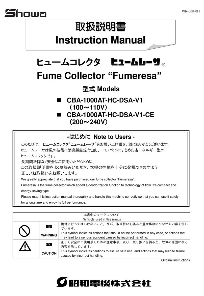
Chiko CBA-080AT2-HI instruction manual

WAM
WAM WAMFLO FOOD FN200X Assembly and main instructions for use and maintenance

DustEZE
DustEZE EC-560 Booklet

laguna
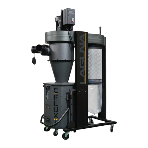
laguna X Flux 10 manual

Oneida Air Systems
Oneida Air Systems Super Dust Gorilla 2hp owner's manual