Generic ZBL-R620 User manual

ZBL-R620/630
Rebar Locator
Operation Manual

Operation Manual for ZBL-R620/R630 Rebar Locator
Contents
1. General Introduction………………………………………………..1
1.1 Basic Working Principles …………………………………………………1
1.2 Components of ZBL-R620/R630…………………………………………1
1.3 System Interface……………………………………………………………2
2. Quick Access. …………………………………………………….2
2.1 System Connection……………………………………………………….3
2.2 Startup…………………………………………………………………….4
2.3 System Reset……………………………………………………………….4
2.4 Choosing Scan Mode………………………………………………5
2.5 Parameter Settings………………………………………………………5
2.6 Scan Operation……………………………………………………………7
2.7 Data Display………………………………………………………………10
2.8 Data Transmission………………………………………………………10
2.9 Deleting Data………………………………………………………12
2.10 System Settings………………………………………………………12
3. Troubleshooting………………………………………………….12
3.1
No display when booting
………………………………………………12
3.2
No signal
…………………………………………………………………13
3.3
No keypad tone
…………………………………………………………13
4. Technical Indicators……………………………………………….13
Appendix:General Principles of Rebar Testing…………………..14

Operation Manual for ZBL-R620/R630 Rebar Locator
ZBL-R620/R630 Rebar Locator is designed for the measurement of concrete cover,
bar diameters, rebars distribution and trend.
1. General Introduction
1.1 Basic Working Principles
From its probe the apparatus emits an electromagnetic field into the interior of the test
area, and then receives the induced magnetic field emitted from ferromagnetic media
such as rebars, which is then converted into an electrical signal. The main instrument
system allows real-time analysis and treatment of the electrical signal, displays the signal
in several different forms such as image, data, and sound etc. enabling the correct
determination of rebar location, thickness of concrete cover, and rebar diameter.
1.2 Components of ZBL-R620/R630
ZBL-R620/R630 Rebar Locator is composed of a main instrument body, a probe, a
scan car (ZBL-R630 only) and signal transmission wire.
The probe has direction sensitivity. The signal is strongest when the probe and the
rebar directions are parallel, on the contrary the signal is weakest when the probe and
rebar directions are perpendicular to each other.
The scan car real-time correctly records the displacement of the probe.
Note: when measuring with the scan car, it is better to move the car in a smooth,
uniform motion.
ZBL-R620/R630 Rebar Locator standard accessories (Fig. 1.1)
Fig. 1.1 Components of ZBL-R620/R630 Rebar Locator
Scan Car
(ZBL-R630 only)
Universal Probe
Signal Cable
Scan Car connection
Back
Menu
Save
Confirm
Up
On / Off Switch
Left
Screen
Right
Down
Power socket
Indicator light
USB Port
Scan Car connection
port
Probe connection
port
Battery housing

Operation Manual for ZBL-R620/R630 Rebar Locator
1.3 System Interface
The ZBL-R620/R630 utilizes a multi-level menu management system.
The menu operation interface is used to choose functions and set parameters,
including: (shown in Fig. 1.2)
Main Menu interface
Parameter Setting interface
Parameter Amendment interface
Soft-keyboard interface
Fig. 1.2 Menu Operation Interface
The testing interface is used to scan data and display image, including: (shown in Fig.
1.3)
General test (scan)
Profile-scan (ZBL-R630 only)
Grid-scan (ZBL-R630 only)
2. Quick Access
Before using the apparatus outdoors it may be useful to first familiarize yourself with
Main Menu interface Parameter Setting interface
ParameterAmendment Soft-keyboard interface
General-scan interface Profile-scan interface Grid-scan interface
Fig. 1.3 Testing Interface

Operation Manual for ZBL-R620/R630 Rebar Locator
the instrument by performing a number of tests in your home or office, prepare simple
scenarios which mimic onsite working environments.
Prepare some non-tensile rebars (use the two thick rebars to imitate the main rebar,
and use the thin rebars to imitate
the top redar), plexiglass boards
(or other non-ferromagnetic
materials such as wooden
board), the board thickness is
about 25mm
Put the rebars on a plane and
keep them away from
ferromagnetic materials. Put the
plexiglass board over the rebars. (Fig. 1.4)
2.1 System Connection
Connecting the Probe (Fig. 2.1)
Insert the plug (black) of the signal
line into the socket on the left of the
rebar locator, rotate clockwise and
lock it tightly in place. Insert the
other end of the signal line into the
socket on the probe and again lock it
tightly.
Note:There is no directional difference
in the signal line.
Connecting the Scan Car(
((
(Fig. 2.2)
))
)(ZBL-R630 only)
When inserting the scan car plug into its socket ensure to align the red dots, one on
the apparatus with one on the signal line plug.
Caution: When inserting or removing the cable be sure to hold the grip at the plug end of
the cable, otherwise the wiring my become loose.
Note:There is no directional difference in the signal line.
Attach Scan Car (Fig. 2.3) (ZBL-R630 only)
Correct Incorrect
Fig. 2.2 connect with Scan Car
M
ain rebar
Top rebar
Fig. 1.4
Fig. 2.1

Operation Manual for ZBL-R620/R630 Rebar Locator
Place the probe in the correct direction (with the ports of the probe and Scan Car in
same direction, see fig 2.3), the central hole of the probe must be aligned with the raised
point on the scan car. The probe should click firming and tightly into place.
Caution: When removing the probe from the scan car, open the two red clips and push the
probe out.
2.2 Startup
Press the power On/Off key “ ” and the rebar locator begins to operate.
The screen displays the startup interface (Fig. 2.4):
The displayed information is as follows:
-Name of the Company
-Name and model number of the Rebar Locator
-Version Number of Rebar locator
-Remaining battery life
-Todays date
When the remaining power of the battery is low, the bar flashes three times, and there is
a short beeping sound, indicating that the battery must be re-charged.
If the automatic self-test is OK, it automatically enters the menu display after about five
seconds.
Shortcuts in Main Menu interface:
【→
→→
→】key, background light on/off switch;
【↑, ↓】keys, move cursor up or down;
【Enter】key, access the highlighted option
2.3 System Reset
The reset operation is used to elimination instrument interference coming from
environmental factors, and ensures that the test results are accurate and reliable. Before
implementing a reset operation hold the transducer in the air, away from magnetic
materials, and then begin the reset operation as detailed below. After 3 seconds, the
current thickness value displays as “0” to indicate that the reset is complete, the display
will then access “test waiting” status.
The system reset can be operated by the following two methods
1) Auto reset – when instrument accesses scan interface an automatic reset operation is
implemented.
2) Manual reset – press 【Enter】key when in scan-test interface, to implement reset
operation.
Fig. 2.3 Attach and remove
Fig. 2.4 Startup Display

Operation Manual for ZBL-R620/R630 Rebar Locator
Caution:
During detection process, it is advised to implement a reset operation about every ten
minutes.
If test data is unreliable, implement reset, then re-test.
2.4 Choosing Scan Mode
ZBL-R630 Rebar Locator provides several scan and work modes, the user can select
the most suitable mode according to their requirements.
Measuring modes: general test, profile-scan, and grid-scan.
Press 【Enter】key to access the highlight option
Caution: Each scan mode has corresponding parameter setting interface.
(Select the different mode to watch the corresponding video)
2.5 Parameter Settings (Fig. 2.5)
Set related parameters according to testing component situation, including object code,
diameter forecast, design thickness, component type, etc.
【↑, ↓】keys, move cursor;
【Enter】key, access highlight option;
【Back】key, save current parameter setting, return to
previous menu, and reset the system;
【Menu】key, return to main menu interface.
Parameter amendment:
1) General situation
【↑, ↓】keys, select the parameter required;
【Save】key, save current setting, return to parameter setting interface.
2) Object code settings
Select the “object code” option, the soft-keyboard will display.
Select the digit which requires modification
Press【← , →】keys, move the cursor to the digit which requires modification;
Press 【↓】key, a cursor displays in the top-left corner of soft-keyboard;
Press 【Back】key, return to parameter setting interface.
Select character
【↑, ↓、←、→】keys, move cursor to select character;
【Enter】key, select the character at present cursor point,
and return to previous menu.
E.g. (shown in video)
Move the cursor to “general test” option, press 【Enter】
key to access parameter setting interface. (Fig. 2.6)
1) Object code -- Object code is composed of six characters; numbers, letters or
Fig. 2.5 General Test
Fig. 2.6 object code setting interface

Operation Manual for ZBL-R620/R630 Rebar Locator
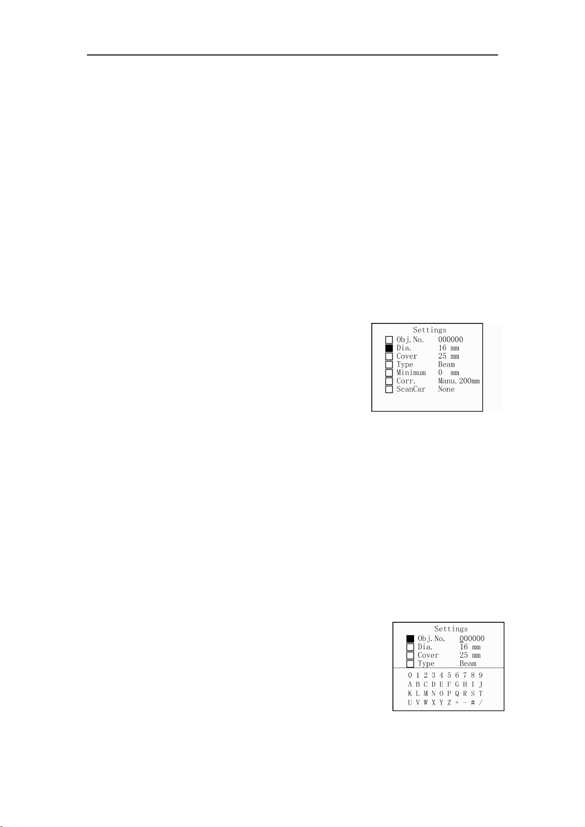
symbols. The initial object code is 000000. When restarting, enter the parameter
setting interface, the initial object code is the previously used code incremented by
one character.
Move the cursor to “object code”, press 【Enter】key, the curser moves to below the
first digit of the code.
Press 【←、→】keys, move the cursor to the digit requiring modification;
Press 【↓】key, a cursor displays in the top-left corner of soft-keyboard;
Press 【↑, ↓、←、→】keys, select a character from the soft-keyboard;
Press 【Enter】key, the selected character now appears in the new object code.
The cursor of object code moves to the next digit and the cursor in soft keyboard will
disappear.
If the next digit needs to be changed, repeat the operation above.
When the object code setting is complete, press the【Save】key to save this object
code. The cursor will disappear, and the interface automatically returns to the
parameter setting interface.
2)Diameter setting – Set the test rebar diameter. The initial value is automatically set to
the previously used rebar diameter value.
When accessing the current setting, the cursor will be shown beneath the diameter value.
Press 【↑, ↓】keys, to increase or decrease the rebar diameter value;
Press 【Save】key, setting are saved, the cursor disappears and the interface
automatically returns to the parameter setting interface.
3) Thickness setting – Set the concrete cover thickness of test rebar, the available range
is 10 ~ 99mm, the initial value is automatically set to the previously used rebar thickness.
When setting thickness:
Press 【↑, ↓】keys, increase or decrease the thickness value,
Press 【Save】key, save setting, the cursor disappears, and the interface
automatically returns to the parameter setting interface.
4) Concrete component type – type of concrete component, including “beam” and
“board”.
Press 【↑, ↓】keys, switch between beam and board. It can automatically judge
if the value of thickness conforms to the international 50204 standard.
5) Minimum thickness – when fast general testing, set the allowed minimum concrete
cover thickness of test rebar. The available range is 0 ~ 100 mm, the initial value is 0 mm.
Press 【↑, ↓】keys, set the minimum concrete cover thickness;
Press 【Save】key, save current setting, the cursor disappears, and the interface
automatically returns to the parameter setting interface.
When the concrete cover thickness is found to be smaller than the minimum thickness,
the apparatus will give a warning. In such an event the thickness value will not be
displayed or saved.
Note: When the minimum thickness is set as 0, the alarm function may be
unavailable.
6) Data correcting – There are two modes, “manual” and “none”, the initial mode is set to
“none”, in which case the apparatus will not make any corrections to the data. To access
this option,

Operation Manual for ZBL-R620/R630 Rebar Locator
Press 【↑, ↓】keys, to switch the select between “manual” and “none”;
If the “manual” mode is selected, the apparatus corrects the test results by
setting the distance from two neighboring parallel rebars to the test rebar. This function
may improve the accuracy of the test results. The available range is 50 ~ 110 mm. To set
the value of the distance to the neighboring rebars, first select the “manual” mode then;
Press【→】key, move the cursor to the digit which need modified;
Press 【↑, ↓】keys, to amend the data;
Press【Save】key, save current setting, the cursor disappears, and the interface
automatically returns to the parameter setting interface.
Note: This function may not fully eliminate the influence coming from the
neighboring rebars.
7) Scan car (ZBL-R630 only) – It has two options, “on” and “off”. If the scan car is to be
used, select “on”, otherwise select “off”.
Press 【Back】key, save the setting and access the testing interface.
If it is in “parameter setting” interface
Press 【Menu】key, return to main menu.
2.6 Scan Operation
ZBL-R620 provides three scan modes , ZBL-R630 provides three scan modes
1) General Test: It is the basic scan mode of R630. It accurately measures the
thickness of concrete cover and the diameter of rebar, it may also judge if the
component conforms to international standards.
2) Profile Scan (ZBL-R630 only): Displays rebar’s distribution in concrete’s profile style,
suitable for situations when rebars have sparse distribution, we suggest to use this
sort of scan in column and plate components’ detection.
3) Grid Scanning (ZBL-R630 only): Displays the rebar distribution over a single plane,
suitable for situations when rebars have sparse distribution, we suggest to use this
sort of scan in plate components’ detection.
Introduction of shortcuts:
【→】key, adjust measuring range(status bar indicate: / );
【←】key, switch save mode between “auto” and “manual” (In general test mode,
it indicate A/M);
【↑】key, shortcut to diameter-test (suitable for general test mode);
【↓】key, switch work mode between “high-resolution rebar” and “general rebar”
(status bar indicator: );
When parameter setting is completed, press 【Back】key, the system accesses the
“test waiting” status.
Note: The system will reset first. When the reset is completed, it is ready to begin testing.
The scan starting point should be selected first, and then the system will save the scan
results. This process is discussed in more detail below.
2.6.1 Pre-scanning

Operation Manual for ZBL-R620/R630 Rebar Locator
Fig. 2.7 Pre-Scanning
In order to know the rebar’s general distribution a
pre-scan may be performed on the concrete element. It is an
important part when selecting scan starting point. A pre-scan
allows real-time display of test information without saving
data.
Generally, the rebars of the top layer are located first, and
then a measurement of the central point between two top layer
rebars is needed in order to locate lower layer rebars.
1) Rebar Location (Fig. 2.7, also see video)
Put the probe on the surface of the concrete element;
ensuring that the probe is parallel to the rebar. Be sure to move the probe smoothly and
evenly in a uniform motion. When the probe moves closer to the rebar, the signal strength
bar rises, the signal value is larger, and the concrete cover thickness value becomes
lower; once the peak value has been reached the instrument will produce a “beep” sound,
and the screen displays related information. The display style differs according to the
different scan mode.
T o accurately determine the peak of the signal move the probe in the opposite
direction until the signal value is largest, and the thickness is the lowest. The central line
of the probe is then the accurate location of the rebar. Select the central location of the
two rebars which have largest distance between each other as the starting point of
scanning. (Please mark this point with a pen)
2) Rebar Direction (Fig. 2.8, video)
The direction of rebars can be detected by the
following two methods.
When the rebar location is known, rotating the
probe directly on the rebar. When the signal
value is the largest and the thickness value is
the smallest, the direction of the probe is the
direction of the rebar.
Detect two rebars location along two parallel
measuring lines, the connected line between the
two locations is then the direction of the rebar. (See fig. 2.8)
3) Estimate the rebar diameter
When the probe is located directly on the rebar, and is parallel to the rebar.
Press 【↑】key, the screen displays the rebar diameter and the concrete cover
thickness.
Note: There is a black triangle symbol before the thickness value; it means the thickness
does not correspond to the pre-set diameter.
In abnormal testing conditions, the rebar diameter may not be measured.
2.6.2 Start Scanning (Save Scanning)
Put the probe in the scan starting point as determined by the pre-scan, move the
probe, the test result may vary with the probe location
1) General Test
Fig. 2.8 Rebar Distribution
Test Line 1
Test Line 2

Operation Manual for ZBL-R620/R630 Rebar Locator
When the rebar is detected by the probe, the system locks the thickness, in manual
mode, press 【Save】key, save test result, and the save object code incremented by one.
In auto save mode, the save number automatically incremented by one.
When the probe is parallel to and directly above the rebar, and the probe and the rebar
have the same direction:
Press 【↑】key to estimate the rebar diameter.
The screen displays the practical test rebar diameter and thickness.
Note: There is a black triangle symbol before the thickness value; it means the thickness
is not related with the pre-set diameter.
2) Profile Scan
Press 【Save】key, access “waiting for save scan result” status. There is a black
square on the top left of the screen, it indicates the location of the probe. Move the
probe evenly and smoothly, when the probe is closer to the rebar, the signal strength
bar is higher, the thickness is smaller; A “beep” sound means the probe have already
crossed the centre of the rebar, and a black dot will appear to indicate the location of
the rebar. The concrete cover thickness and the rebar coordinate (the distance
between the rebar and the starting point, unit: cm) will be displayed above the black
dot. The instrument automatically saves the test data and the image.
Press 【Back】key, return to parameter setting interface.
Press 【Menu】key, access the main menu interface.
Note: The maximum distance displayed on every page is 1.2m, if the test results exceed
this length the screen will automatically turn to the next page, and the page number is
increased by one.
3) Grid Scan
Select the direction to start the scan,
Press 【Save】key, access “waiting for save scan result” status.
Press 【Back】key, return to parameter setting interface.
When the scan of the first direction is completed, the user may scan another direction.
Press 【Save】key, stop the current scan of the first direction.
Press 【↑】key, change the scan direction.
Repeat the operation above, complete scan of another direction. A X, Y-2D scan is
completed.
2.6.3 Second scan
A Second scan is scanning several test lines along X’s direction (X2, X3, X4,…, Xn)
or Y’s direction (Y2, Y3, Y4,.…, Yn) based on an initial first scan(Fig. 2.9). The second
scan produces the real distribution of rebars, the test data is then transferred to computer
where Windows analysis software will display rebar distribution image of rebar according
to test data. (Fig. 2.10)
Principles of second scan operation:
The beginning of the first and second scan should lie on the same line perpendicular
to the scanning direction.

Operation Manual for ZBL-R620/R630 Rebar Locator
Second scan updates scan data only, doesn’t update the rebar’s distribution image.
The second scan operation introduced above is the normal operation, users don’t
need to scan every adjacent bar, instead a cross-bar scan is performed. For the Cross-bar
scan a single bar in the x-direction and a single bar in the y-direction are selected for use
during a second-scan operation. In order to use Windows software analysis the operator
is required to record the separation between the parallel test lines of the first and second
scans. For queries related to the use of the Windows software, the reader is directed to
the R650 software operation manual.
2.7 Data Display
Display the saved component, data and image
1) In Menu interface, move the cursor to “data display” option.
Press 【Enter】to access the “components list” interface
2) In data display interface
The left column shows the “components list”, listed in descending order with the newest at
the top. The right column shows the “data display” area, displaying the statistical
information of saved data for the current concrete element.
【↑, ↓】keys, move cursor to the concrete element you want to select.
【← ,→】keys, allow movement to the next or previous pages of “concrete
elements menu” shown in the left column of the screen;
Press 【Menu】key, return to main menu.
Press【Enter】key to access the data display interface, the screen displays data or image
(profile, grid).
【↑, ↓】key, allow movement to previous or next page in up-down direction
(profile or grid scan mode);
【 ← ,→ 】 key, allow movement to previous or next image in left-right
direction(profile or grid scan mode).
2.8 Data Transmission
Using data transmission any data saved within the appliance can be transferred to an
Fig. 2.9 Fig. 2.10

Operation Manual for ZBL-R620/R630 Rebar Locator
external storage device, personal computer or notebook computer. Make sure that the
computer has already been installed with the “rebar detect data treatment software”
before transmission. Use a USB cable to connect the USB port of the instrument and USB
port of the computer; if this data transmission function is used for the first time, you need
to install appropriate driver first, the reader is directed to the appendix of R630 software
operation manual.
:Please strictly obey the operation order following strictly.
1) Connection between reinforced detector and computer
Use a USB cable to connect the instrument and computer. If the device is not
recognized and the computer indicates that it has “found new hardware device”
the user is directed to the appendix of R650 software operation manual for
further advice.
2) Computer operation
Launch “Rebar test data analysis software”, select Tools
menu, then select Data transmission, the transmission
window shall now appear (see fig. 2.11).
Select rebar test data (R630) from data type, then
select USB port as data transmission port.
press the Transmission key, pop-up window
shown in fig. 2.12 appears.
Input file name and press Save key. The
computer is now ready to receive
data transmitted from the instrument.
The screen will displays “port
initialization finished”.
3) Rebar locator operation
Select “data transmission” option
from ZBL-R620/R630 menu
press【Enter】key to access
data transmission interface
(fig. 2.13);
press 【Enter】key again to
begin transmitting data (fig.
Fig. 2.11
Fig. 2.12
Fig. 2.14
Fig. 2.13

Operation Manual for ZBL-R620/R630 Rebar Locator
Fig. 2.16 System Settings Interface
2.14) . When the progress bar is full, transmission is complete and the display
will automatically return to the menu interface.
4) When transmission is complete, the transmission dialogue exits automatically and the
user can open the newly created document and begin analysis.
2.9 Deleting Data
This function will delete all data, if you want to keep the
data, please transfer it to a computer or other external device.
The screen displays “Do you really want to delete the
data?” (Fig. 2.15)
Press 【Back】key, do not delete and return to main menu interface;
Press 【Enter】key, begin deleting, the screen displays “deleting…”.
2.10 System Settings
When accessing the system setting function, the
information below may be amended. (Fig. 2.16)
Date: Year / Month / Day
Time: Hour / Minute / Second (24hours mode)
Power status may be checked in this interface.
Operating method:
Press 【↑, ↓, ←, →】keys, move the cursor to the item which requires
modification;
Press 【Enter】key, access the highlight option;
Press 【↑, ↓】keys, change the value;
Press 【Enter】key, save settings and return to main menu;
Press 【Back】key, return to main menu.
3. Troubleshooting
3.1 No display when booting
After booting, if there is nothing displayed (blank screen), please first check power
status.
Connect the instruments power supply using the charger provided, the green light
in the upper-right corner of the screen will light up when connected properly;
startup the instrument as usual, the screen will display as normal, the instrument
Fig. 2.15 Deleting Data

Operation Manual for ZBL-R620/R630 Rebar Locator
can work after being fully charged (or while connected to the charger).
If there is still no display after connecting to the charger, please check charger or
call our company hotline.
3.2 No signal
No signal display when scanning.
Place the transducer away from any magnetic materials (in the air), and perform a
system reset. Begin scan after the status bar indicates that reset is complete.
Check if the connection of transducer’s signal cable is correct.
Check if the power is low, (battery power 0%).
3.3 No keypad tone
Check system settings, turn keyboard tones on, then save settings.
If settings are normal but there are still no keypad tones, call our company hotline.
4. Technical Indicators
Table 1.1: Ranges of Measuring Concrete Cover: Unit: mm
Bar Diameter Concrete cover over small
measuring range
Concrete cover over large
measuring range
φ6 ~φ8 6 ~ 70 10 ~ 100
φ10 ~φ18 9 ~ 80 16 ~ 126
φ20 ~φ28 10 ~ 86 20 ~ 160
φ32 ~φ36
φ40 ~φ50 16 ~ 90 28 ~ 180
Table 1.2: MeasurementAccuracy (covers) Unit: mm
Accuracy Concrete cover over small
measuring range
Concrete cover over large
measuring range
±1 6 ~ 59 10 ~ 79
±2 60 ~ 69 80 ~ 119
±4 70 ~ 90 120 ~ 180

Operation Manual for ZBL-R620/R630 Rebar Locator
Table 1.3: Measuring Range of Rebar Diameter (φ6 mm ~ φ32 mm)
Rebar Diameter Minimum Thickness of Concrete
Cover
Maximum Thickness of
Concrete Cover
6 8 60
8 12 62
10 12 66
12 14 68
14 14 68
16 16 72
18 16 72
20 18 74
22 18 74
25 20 76
28 22 76
32 22 80
Table 1.4: MeasurementAccuracy (Bar Diameter) Unit: mm
Bar Diameter 6 8 10 12 14 16 18 20 22 25 28
32
Accuracy +2 ±2
±2
±2
±2
±2
±2
±2
+3
-2 ±3
+4
-3
-4
Appendix A: General Principles of Rebar Testing
Scan surface should be smooth and flat. If the surface is too rough to clean, put a
thin board on the scan surface, after completing the scan the board’s thickness
must be subtracted from the scan results.
Move the transducer in a unidirectional, uniform motion during the scan process.
Direction of scan should be perpendicular to the direction of the rebar (fig. A.2),
otherwise this may cause misjudge (Fig. A.1)
For mesh rebar, locate the rebar of upper layer first then detect the central line of
two upper layer rebars. This central line may then be used to locate the lower
layer rebar.
Fig. A.1 Fig. A.2
╳
╳╳
╳
√
This manual suits for next models
1
Table of contents
Other Generic Analytical Instrument manuals