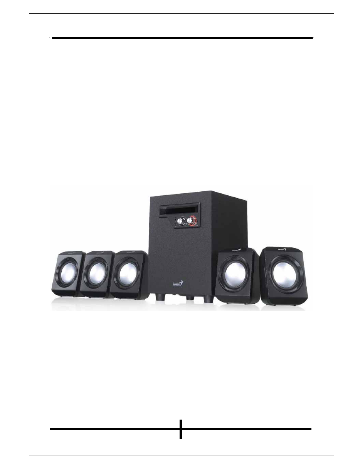
Service Guide SW-5.1 1020
Contents
Document Version ............................................................................................................................ 2
Contents............................................................................................................................................ 3
Use.................................................................................................................................................... 4
Use Guide .................................................................................................................................. 4
Safety Caution ........................................................................................................................... 4
Chapter 1: How to Dispose Returned Defective Products ............................................................... 5
1.2 Troubles ............................................................................................................................... 6
1.2.1 No Power and Indicator Lamp Inoperative ............................................................... 7
1.2.2 No Sound................................................................................................................... 8
1.2.3 No Sound from Front Left or Right Channel ............................................................ 9
1.2.4 No Sound from Rear Left or Right Channel ........................................................... 10
1.2.5 No Sound from Middle Channel ............................................................................. 11
1.2.6 No Bass.................................................................................................................... 12
1.2.7 Noise and Current Noise ......................................................................................... 13
1.2.8 Earphone Socket Inoperative................................................................................... 14
1.2.9 Noice Bass Potentiometer ....................................................................................... 15
1.2.10 VOL (Volume) Inoperative.................................................................................... 16
Chapter 2 Product Specifications ................................................................................................... 17
2.1 Satellite....................................................................................................................... 17
2.2 Subwoofer ................................................................................................................ 17
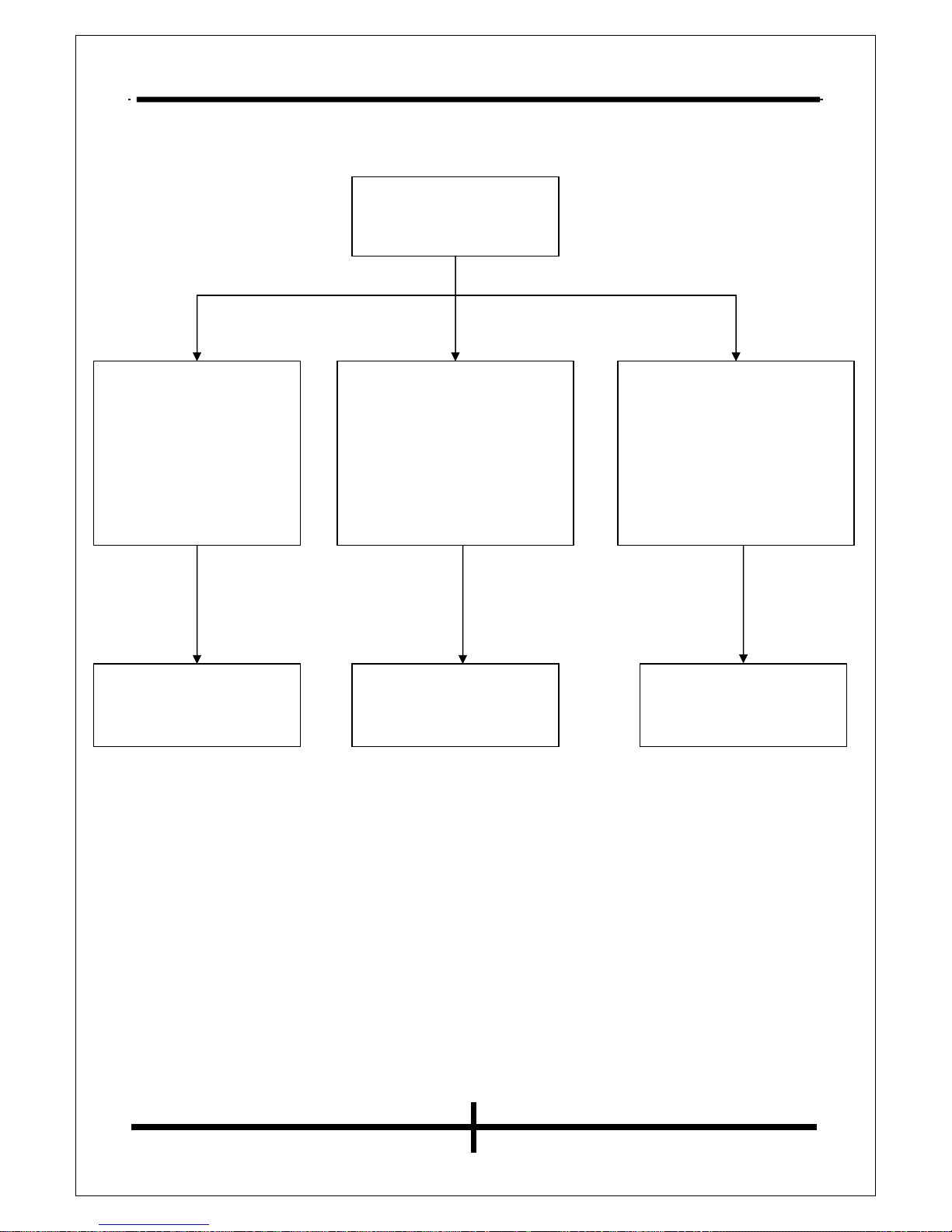
Chapter 3 Block Diagram............................................................................................................... 18
Chapter 4 Rendering after Assembly.........................................................................................19-20
Satellite .................................................................................................................................. 19
Subwoofer ............................................................................................................................. 20
Chapter 5 Material List..............................................................................................................21-22
Satellite .................................................................................................................................. 21
Subwoofer .............................................................................................................................. 22
Chapter 6 Electric Schematic Diagram .....................................................................................23-24
Version No. 1.0 Page 3 of 24