Genius SW-J2.1 1200 User manual

Service Guide SW-J2.1 1200
SERVICE GUIDE
KEY SYSTEM CORP
Version 1.0 Page 1 of 23
All manuals and user guides at all-guides.com

Service Guide SW-J2.1 1200
Revision History
Version Date Change
1.0 05/04/2009
Version 1.0 Page 2 of 23
All manuals and user guides at all-guides.com

Service Guide SW-J2.1 1200
Revision History………………………………………………………………….2
Table of contents……………………………………………………………...…3
Getting Start…………………………………………………….………………...4
Conventions Used in this Guide…………………………………………….…4
Safety Precautions………………………………………………………………4
Chapter 1. How to Handle Defective Returns……………………………….5
1.2 Problem………………………………………………………………………6
1.2.1 No power,LED (indicator)unlighted……………………………….7
1.2.2 No sound…………………………………………………………….…….8
1.2.3 Right or left channel no sound….……….……….……….……..….……9
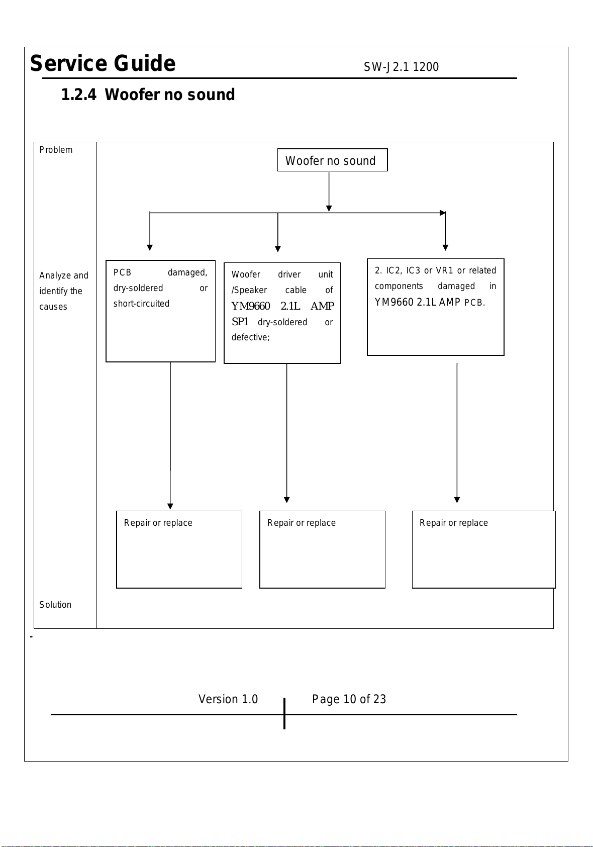
1.2.4 Woofer no sound….……….……….……….………….….……….……10
1.2.5 Noise………………………………….…………………………….…..…11
1.2.6 LED indicators no light…………………………….….……………..….12
1.2.7 Headphone jack output no sound……………………………..………..13
1.2.8 VR, headphone jack or line-in jack abnormal……..………….………..14
Chapter 2. Specification…………………………………………………….……15
Satellite…………………………………………………………………….……15
Woofer……………………………………………………………………………15
Chapter 3. Block diagram…………………………………………..…………..16
Chapter 4. Exploded view………………………………………………………17
Subwoofer……………………………………………………………….……….17
Satellite…………………………………………………..…….…………………18
Wired-control…………………………………………………………………….19
Chapter 5. Part list…………………………………… …………….…………...20
Woofer………………………………………………………….……………….. 20
Satellite…………………………………………………………………………...21
Wired control……………………………………………………………….…..21
Chapter 6 Important notes……………………………………………………….22
Chapter 7 Schematic diagram……………………………………..……………23
Version 1.0 Page 3 of 23
Table of Contents
All manuals and user guides at all-guides.com

Service Guide SW-J2.1 1200
Getting Started
Conventions Used in the Guide
Pay Special Attention: Instructions that are important to remember and may prevent
mistakes.
Caution: Information that, if not followed, may result in damage to the product.
Safety Precautions
The following precautions should be observed in handing the speaker described in
this guide:
Place the speakers on a flat, level and stable surface.
Do not place the speakers in environments subject to mist, smoke, vibration,
excessive dust, salty or greasy air, or other corrosive gases and fumes.
Do not drop or jolt the speakers.
Donotallowanythingtodrop into the subwoofer case through its ventilator, as it
could result in fatal electric shock or fire.
Place the unit far enough from other equipments for good heat dissipation.
Do not perform any maintenance with wet hand.
Preventforeignsubstance,such as water, other liquids or chemical, from entering
the speakers while performing maintenance procedures on the speakers.
Version 1.0 Page 4 of 23
All manuals and user guides at all-guides.com

Service Guide SW-J2.1 1200
Chapter 1. How to Handle Defective Returns
1.1 Overview
Function NG Function OK
FunctionNG
FunctionOK
Version 1.0 Page 5 of 23
Receiving Defective speaker from customers
Return the speakers with proper
repacking to customers
Verifying problems
Proceeding
Necessary tests
Analyzing possible
Malfunction cause
Deciding & proceeding the
Rectification methods
Replace necessary
Defective parts
Verifying problems
Proceeding
Necessary tests
All manuals and user guides at all-guides.com

Service Guide SW-J2.1 1200
1.2 Problems
Item Problem Description
1.2.1 No power,LED (indicator)no light
1.2.2 No sound
1.2.3 Right or left channel no sound
1.2.4 Woofer no sound
1.2.5 Noise
1.2.6 LEDindicatornolight
1.2.7 Headphone jack output no sound
1.2.8 VR, headphone jack or line-in jack abnormal
Version1.0 Page6of23
All manuals and user guides at all-guides.com

Service Guide SW-J2.1 1200
*Attention
Please follow the numbered sequence marked within parenthesis given in
individual
Flow chat in that this is the best-recommended sequence to rectify the problems.
1.2.1 No power,LED (indicator)unlighted
Problem
Analyze
and
identify
the
causes
Solutions
Version 1.0 Page 7 of 23
No power,LED (indicator)unlighted
Repair or replace
Defective transformer
Defective or damaged
AC cable, or power
switch
resolder or replace
Or caused by the following:
1. transformer secondary wire loosely connected with PT1 jack in
YM9660 2.1LAMP.
2. Dry soldering of PT1 in YM9660 2.1L AMP
3. Copper foil of YM9660 2.1LAMP PCB broken
4. G6 plug of the wired-control defectively connected or damaged
5. VR2 on the ym9660-2.1L CON PCB damaged or dry-soldered
6. JK2 on YM9660 2.1L PCB defective
All manuals and user guides at all-guides.com

Service Guide SW-J2.1 1200
1.2.2 No sound
Problem
Analyze and
identify the
causes
]
Solutions
Version 1.0 Page 8 of 23
No sound
PCB short-circuited,
dry soldered or broken;
Or G6 plug of the
wired-control
defectively connected
or damaged
JK2 in YM9660 2.1L AMP
PCB defective
VR2 in YM9660 2.1L CON
PCB damaged or PCB
copper foil broken
Repair or replace
Repair or replace
Or caused by the following defective
components in YM9660 2.1L AMP
PCB: IC1,IC4,IC3,IC2,Q1,
ZD1, ZD1,JK1,EC6, R21,EC6,
JK1,SP1
Repair, resolder or
replace
All manuals and user guides at all-guides.com

Service Guide SW-J2.1 1200
1.2.3 Right or left channel no sound
Problem
Analyze and
identify the
causes
Solutions
Version 1.0 Page 9 of 23
Replace or
replace
Re-connect ,
replace or repair
Repair or
replace
JK6,JK7 or VR2 in YM9660
2.1L CON PCB defective;
IC1 or IC3 or related
components damaged in
YM9660 2.1LAMP PCB
Driver unit or speaker
cable defective or
loosely connected
Audio cable defective
or loosely connected
PCB damaged, dry-soldered or
short-circuited;
JK1, JK2 and JK3 in YM9660
2.1L AMP defective or
damaged;
G6 plug of the wired-control
Right or left channel no sound
All manuals and user guides at all-guides.com

Service Guide SW-J2.1 1200
1.2.4 Woofer no sound
Problem
Analyze and
identify the
causes
Solution
-
Version 1.0 Page 10 of 23
PCB damaged,
dry-soldered or
short-circuited
2. IC2, IC3 or VR1 or related
components damaged in
YM9660 2.1LAMP PCB.
Repair or replace Repair or replace
Woofer driver unit
/Speaker cable of
YM9660 2.1L AMP
SP1 dry-soldered or
defective;
Repair or replace
Woofer no sound
All manuals and user guides at all-guides.com

Service Guide SW-J2.1 1200
1.2.5 Noise
Problem
Analyze and
identify the
causes
Solutions
Version 1.0 Page 11 of 23
Filter capacitor/ diode dry-soldered
or damaged, pls check EC14,
EC12, EC1, EC6, EC13, D1,
D2, D3, D4;
The power supply of each IC is
normal or not;
PCB dry-solder or broken
Check and replace Repair or replace
Repair
Driver units damaged
Woofer cabinet leaks,
closed not well.
Or caused by vibration from
too long lead wire of driver
units
Noise
All manuals and user guides at all-guides.com

Service Guide SW-J2.1 1200
1.2.6 LED indicator no light
Problem
Analyze and
identify the
causes
Solutions
Version 1.0 Page 12 of 23
Check and replace
1. LED1 defective
2. YM9660 2.1L CON PCB short-circuit
LED indicato
r
no li
g
ht
All manuals and user guides at all-guides.com

Service Guide SW-J2.1 1200
1.2.7 Headpone jack output no sound
Problem
Analyze and
identify the
causes
Solutions
Version 1.0 Page 13 of 23
Check and replace
JK7 in YM9660 2.1L CON PCB defective
or its related copper foil broken
Head
p
hone
j
ack no use
All manuals and user guides at all-guides.com

Service Guide SW-J2.1 1200
1.2.8 VR, headphone jack or line-in jack abnormal
Problem
Analyze and
identify the
causes
Solutions
Version 1.0 Page 164of 23
VR:
Defective VR may cause
wired-control VR or bass VR having
scratching sound when rotating
Check and replace Check and replace
Jack:
JK6 or JK7 in YM9660 2.1L CON
PCB defective
JK2, JK3, or JK1 in YM9660 AMP
PCB defective
VR, head
p
hone
j
ack or line-in
j
ack abnormal
All manuals and user guides at all-guides.com

Service Guide SW-J2.1 1200
Satellite
Normal
NO DESCRIPTION UNIT
R L
LIMIT
1 RATED OUTPUT POWER @THD 10% W 6.2 6.2 ≧5.5
2 SENSITIVITY (1KHz) @RATED O/P POWER m V 440 435 450±45
3 SENSITIVITY (1KHz) @1W O/P POWER m V 135 130 130±13
4 MAX INPUT LEVEL@1% THD m V 360 340 350±35
5 DISTOPTION@1kHz 1W OUT % 0.1 0.1
≦0.5
6 FREQUENCY RESPONSE(1KHz -3DB ) LOW Hz 115 115 110±20
7 FREQUENCY RESPONSE(1KHz -3DB ) HI KHz 150 150 150±20
8 S/N@RATED O/P POWER d B 80 80 ≧70
9 CHANNEL UNBALANCE @REF O/P POWER d B 0.3 0.3 ≦1
10 CHANNEL SEPARATION(ONE
CHANNELIN;OTHER CHANNEL INPUT
SHORTING d B 55 53 ≧40
11 HUM NOISE (VOLUME MAX;INPUT SHORTING) m V 0.6 0.6 ≦2
12 HUM NOISE (VOLUME MIN INPUT SHORTING) m V 0.3 0.3 ≦1
Woofer
NO DESCRIPTION UNIT Normal LIMIT
RATED OUTPUT POWER@100HZ
(10%THD) 16.3
1 W ≧15
SENSITIVITY (100Hz) @RATED O/P
POWER 145
2 150±15
m V
32
3 SENSITIVITY (100Hz) @1W O/P POWER m V 30±5
110
4 MAX INPUT LEVEL@1% THD m V 110±15
5 DISTOPTION@100Hz 1W OUT % 0.1 ≦0.5
6 FREQUENCY RESPONSE(100Hz -3DB )
LOW Hz 10 10±5
7 FREQUENCY RESPONSE(100Hz -3DB ) HI Hz 150 150±20
8 S/N RATIO@100HZ RATED O/P
POWER d B 80 ≧70
9 HUM NOISE (VOLUME MAX;INPUT
SHORTING) m V 1.4 ≦2
10 HUM NOISE (VOLUME MIN INPUT
SHORTING) m V 0.5 ≦1
Version 1.0 Page 15 of 23
Chapter 2. Specifications
All manuals and user guides at all-guides.com

Service Guide SW-J2.1 1200
Version 1.0 Page 16 of 23
Chapter 3 Block diagram
All manuals and user guides at all-guides.com

Service Guide SW-J2.1 1200
Subwoofer
Version 1.0 Page 17 of 23
Chapter 4 Exploded view
All manuals and user guides at all-guides.com

Service Guide SW-J2.1 1200
Satellite
Version 1.0 Page 18 of 23
Chapter 4 Exploded view
All manuals and user guides at all-guides.com

Service Guide SW-J2.1 1200
Wired control
Version 1.0 Page 19 of 23
Chapter 4 Exploded view
All manuals and user guides at all-guides.com

Service Guide SW-J2.1 1200
Woofer
Ref.
NO Description Part NO
1 Port tube, plastic, A-822-1 EP41510014
2 Paper port tube, SW-2.1 1200 EP41590071
3 Port tube, A-822-2 EP41510041
4 wooden cabinet, SW-2.1 1200, 169*230*239 EP531200J1A
5 Female plastic buckle, A-858CEV EP41610060
screw, 3.5*14TA EP24150009
6 screw, 3.5*20PA
7 EP24100079
8 scew, 3*12PA EP24100036
9 PCBA, HSW-2.1 1200ALSO-1 EP1P120004
10 plastic bracket at woofer back, P9600-2.1L EP40910384
11 footmat, ∮18*3.0MM EP73060057
12 screw, 4*22PWM EP24140016
13 black washer, M4 EP25020002
14 M4 nut EP25010002
16 Driver unit, A-105-9 EP16040018
17 Male plastic buckle, A-858CEV EP41610064
18 woofer driver unit cloth cover, SW-2.1
1500 EP64000189A
19 scew, 3.5*12PA EP24100030
20 AL heat sink, YM363-2.1 EP23011049
21 L-shaped holder, LX-04 EP22010006
22 bass knob, A-826-1 EP40711120
23 scew, 3*10PM, EP24180032
25 power switch EP19030008
26 tansformer, 230V 50HZ/14V-2.2A EP13500046
27 BT4830, IC EP1C020048
Version 1.0 Page 20 of 23
Cha
p
ter 5 Part list
All manuals and user guides at all-guides.com
Table of contents
Other Genius Speakers System manuals

Genius
Genius SW-G2.1 1250 User manual

Genius
Genius USB SoundBar 200BT User manual

Genius
Genius SW-2.1 850 User manual

Genius
Genius SW-2.1 350 User manual

Genius
Genius GHT-S200 User manual

Genius
Genius SW-HF 5.1 6000 User manual

Genius
Genius SW-HF5.1 User manual

Genius
Genius SP-E06S User manual

Genius
Genius SW-HF5.1 1200 User manual

Genius
Genius SW-HF 5.1 5050 V2 User manual