Gentec-EO PRONTO-Si User manual

PRONTO-Si User Manual Revision 1.5 i

PRONTO-Si User Manual Revision 1.5 ii
WARRANTY
First Year Warranty
The Gentec-EO thermal power detectors carry a one-year warranty (from date of shipment) against material
and/or workmanship defects when used under normal operating conditions. The warranty does not cover
recalibration, or damages related to misuse.
Gentec-EO will repair or replace at our option any Pronto which proves to be defective during the warranty
period; except in the case of product misuse.
Any unauthorized alteration or repair of the product is also not covered by the warranty.
The manufacturer is not liable for consequential damages of any kind.
In the case of a malfunction, contact your local Gentec-EO distributor or the nearest Gentec-EO office to obtain a
return authorization number. Return the material to the appropriate address below.
Contacting Gentec Electro-Optics Inc.
To help us answer your calls more efficiently please have the model number of the detector you are using ready
before calling Customer Support.
Gentec Electro-Optics, Inc.
445, St-Jean-Baptiste, Suite 160
Québec, QC
Canada, G2E 5N7
Tel: (418) 651-8003
Fax: (418) 651-1174
E-mail: service@gentec-eo.com
Website: gentec-eo.com
Lifetime Warranty
Gentec-EO will guarantee any Pronto detector for its lifetime, as long as it has been returned for recalibration
annually, from the shipment date. This warranty includes parts and labor for all routine repairs including normal
wear under normal operating conditions.
Gentec-EO will inspect and repair the detector during the annual recalibration. Repairs at other times will be at
Gentec-EO’s option.
The cost of annual recalibration, or consequential damages from using the detector, is not included.
The only condition is that the detector must not have been subject to unauthorized service or damaged by
misuse. Misuse would include, but is not limited to: laser exposure outside Gentec-EO’s published specifications,
physical damage due to improper handling, and exposure to hostile environments. Hostile environments would
include, but are not limited to: excessive temperature, vibration, humidity, or surface contaminants; exposure to
flame, solvents or water; and connection to improper electrical voltage.

PRONTO-Si User Manual Revision 1.5 iii
SAFETY INFORMATION
Do not use the PRONTO-Si if the device or the detector looks damaged, or if you suspect that the PRONTO-Si
is not operating properly.
Appropriate installation must be done for water-cooled and fan-cooled detectors. Refer to the specific
instructions for more information. Wait a few minutes before handling the detectors after power is applied.
Surfaces of the detectors get very hot and there is a risk of injury if they are not allowed to cool down.
Note: This equipment has been tested and found to comply with the limits for a Class A digital
device, pursuant to part 15 of the FCC Rules. These limits are designed to provide reasonable
protection against harmful interference when the equipment is operated in a commercial
environment. This equipment generates, uses, and can radiate radio frequency energy and, if
not installed and used in accordance with the instruction manual, may cause harmful
interference to radio communications. Operation of this equipment in a residential area is likely
to cause harmful interference in which case the user will be required to correct the
interference at his own expense.
Caution: Changes or modifications not expressly approved in writing by Gentec-EO Inc. may void the
user’s authority to operate this equipment.

PRONTO-Si User Manual Revision 1.5 iv
TABLE OF CONTENTS
1. PRONTO-Si Handheld Laser Probe..............................................................................1
1.1. Introduction.................................................................................................................................................1
1.2. Warnings and Disclaimer ...........................................................................................................................1
1.3. Specifications.............................................................................................................................................2
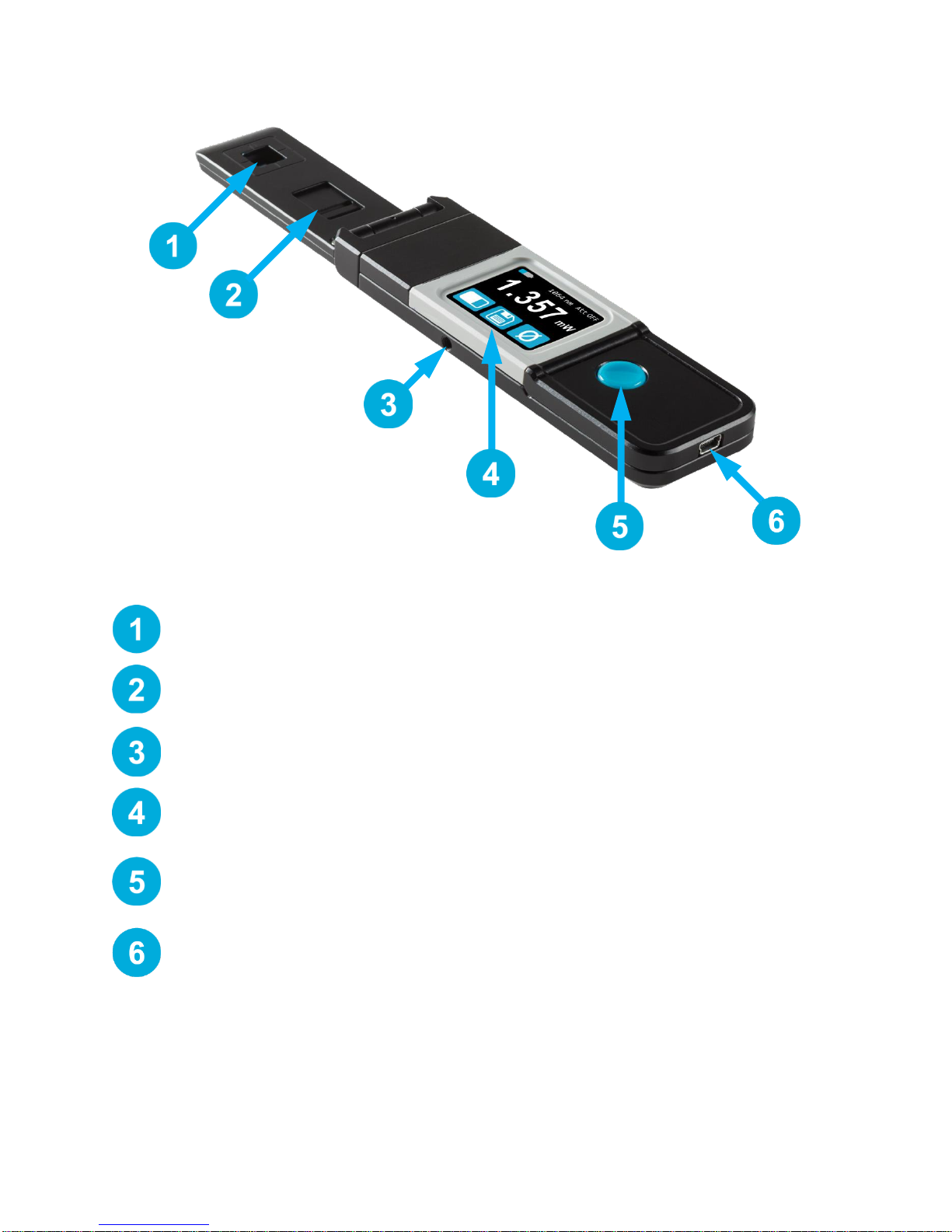
1.4. Mechanical Description..............................................................................................................................4
2. User Interface.................................................................................................................5
2.1. List of Icons................................................................................................................................................5
2.2. Description of the Screens.........................................................................................................................6
3. Operating Instructions ..................................................................................................8
3.1. Turning the Device ON and OFF ...............................................................................................................8
3.2. Changing the SETTINGS...........................................................................................................................8
3.2.1. Changing the WAVELENGTH ............................................................................................................8
3.2.2. Opening and Closing the SETTINGS Menu .......................................................................................9
3.2.3. Changing the ORIENTATION of the Screen ......................................................................................9
3.2.4. Changing the BRIGHTNESS of the Screen........................................................................................9
3.2.5. Getting Information ABOUT the Device..............................................................................................9
3.3. Zeroing .................................................................................................................................................... 10
3.4. Making a Measurement........................................................................................................................... 10
3.5. Acquiring, Transferring and Deleting Data.............................................................................................. 11
3.5.1. Acquiring Data ................................................................................................................................. 11
3.5.2. Transferring Data............................................................................................................................. 11
3.5.3. Deleting the data.............................................................................................................................. 11
4. Safety Instructions.......................................................................................................12
4.1. General.................................................................................................................................................... 12
4.2. Damage to the Optical Absorber Material............................................................................................... 12
4.3. How to Properly Handle the Device........................................................................................................ 12
5. Sources of error...........................................................................................................13
5.1. Zero Offset .............................................................................................................................................. 13
5.2. Offset Drift Due to Temperature.............................................................................................................. 13
5.3. Wavelength ............................................................................................................................................. 14
5.4. Maximum Power...................................................................................................................................... 14
6. Maintenance.................................................................................................................16
6.1. Free Firmware Upgrade.......................................................................................................................... 16
7. Accessories..................................................................................................................17
7.1. Threaded adaptor.................................................................................................................................... 17
Declaration of Conformity....................................................................................................20
Appendix A: WEEE Directive...............................................................................................21
Appendix B: Installing the ProntoDataTransfer Software.................................................22

PRONTO-Si User Manual Revision 1.5 v
LIST OF FIGURES
Figure 1 PRONTO-Si Mechanics............................................................................................................................4
Figure 2 The 6 wavelength buttons can be customized by the user ......................................................................8
Figure 3 The About menu displays important information about your device ........................................................9
Figure 4 Transferring measurements acquired with a PRONTO-Si to a computer............................................. 11
Figure 5 Recommended setup when making a measurement............................................................................ 12
Figure 6 Typical photosensitivity temperature characteristic............................................................................... 13
Figure 7 Typical PRONTO-Si sensitivity vs wavelength...................................................................................... 14
Figure 8 PRONTO-Si maximum power vs wavelength. ...................................................................................... 15
Figure 9Threaded adaptor for PRONTO-Si (203502) with FC adaptor for optical fiber (202367)...................... 17
Figure 10 Distance between sensor surface and optical fiber.............................................................................. 17
Figure 11 To align the adaptor with the sensor, ................................................................................................... 18
Figure 12 Flipping the PRONTO-Si closed when the FC adaptor is attached will damage the touch screen. .... 19
Figure 13 Proper way to store a PRONTO-Si with the threaded adaptor. ........................................................... 19

PRONTO-Si User Manual Revision 1.5 1
1. PRONTO-SI HANDHELD LASER PROBE
1.1. INTRODUCTION
The PRONTO-Si laser probe is designed to be used at low average power densities. It can measure
between 20 pW and 800 mW (at 1064 nm).
The PRONTO-Si can be supplied with an optional stand and/or power supply.
Call your nearest Gentec-EO distributor to repair and/or to recalibrate a PRONTO-Si. To find the nearest
Gentec-EO office or distributor in your country, refer to p. II, Contacting Gentec Electro-Optics Inc.
1.2. WARNINGS AND DISCLAIMER
In no event shall Gentec-EO or any of its affiliates be liable for any indirect, special, incidental or
consequential injury to persons or damage to property caused by the use of any of our products, by
purchasing from Gentec-EO or any of its affiliates, you hereby indicate that you understand and agree to
the following :
Disclaimer
I am fully responsible for the safe application and use of this detector and agreed
to such by completing the sales process.
I will not use a laser device without wearing approved laser safety goggles
designed for such purpose.
I am aware and responsible of safely dealing with any back reflections.
I will not use the detector in violation of any local, state or federal law, and I
understand that it is my responsibility to know and abide by those laws relating to
the ownership and use of the detector in my jurisdiction.

PRONTO-Si User Manual Revision 1.5 2
1.3. SPECIFICATIONS
The following specifications are based on a one-year calibration cycle, an operating temperature of 15 to
28ºC (59 to 82ºF) and a relative humidity not exceeding 80%. Monitors must be stored in an environment
between 10oC to 60oC (50 to 140oF) and a relative humidity not exceeding 90%.
PRONTO-Si
Interface
Touch Screen
Display
Color LCD 28 X 35 mm (128 x 160 pixels)
Measurement Controls
Zero Offset, Wavelength Selection and Reset Data
Data Acquisition and Transfer
On/Off Controls
Maximum of 50 000 Measurements
Screen Personalization
4 screen orientations and 4 brightness levels
Saved Settings
Screen Orientation
Screen Brightness
Wavelength
Effective Aperture
10 x 10 mm
Calibrated Spectral Range
Attenuator OFF:
320 –1100 nm
Attenuator ON:
400 –1100 nm
Power Noise Level
20 pW @ 1064nm
Response Time (10 - 90 %)
0.2 sec
Typical Sensitivity
0.71 A/W @ 980 nm
0.33 A/W @ 1064 nm
ADC
24 bit, 6.8 Hz bandwidth
Calibration Uncertainty
Attenuator OFF
320-399 nm ±6.0%
400-449 nm ±2.0%
450-940 nm ±1.5%
941-980 nm ±2.0%
981-1049 nm ±5.0%
1050-1100 nm ±7.0%
Attenuator ON:
400-980 nm ±4.0%
981-1049 nm ±5.0%
1050-1100 nm ±7.0%
Linearity with Power
± 2 %
Repeatability (Precision)
± 0.5 %
Power Resolution
1 pW
Maximum Power at 980 nm
Attenuator OFF:
40 mW
Attenuator ON:
400 mW
Maximum Power at 1064 nm
Attenuator OFF:
80 mW
Attenuator ON:
800 mW
Maximum Average Power
Density
40 mW/cm2@ 980 nm
80 mW/cm2@ 1064 nm
Operating Conditions
Ambient temperature : 15-28°C
Maximum Relative humidity : 80%
Damage Threshold
100 W/cm2
Absorber
Silicon
Attenuator
Integrated slide-in OD1 attenuator
Dimensions
Open
Closed
41.0W x 216.2L x 13.9D mm
41.0W x 136.0L x 21.5D mm
Weight
155 g

PRONTO-Si User Manual Revision 1.5 3
Specifications are subject to change without notice
Battery Type
USB Rechargeable Li-ion
Battery Life
(Time before the battery needs to
be charged via the USB port)
17 hours (with brightness set at 25%)
Charge Time : 7.5 hours when totally empty
Maximum Battery Cycle Count
(Number of charge cycles before the
battery loses its efficiency)
Approximatively 500 full charges (0-100%)
Mounting Holes (for post)
1 x 8-32

PRONTO-Si User Manual Revision 1.5 4
1.4. MECHANICAL DESCRIPTION
Figure 1 PRONTO-Si Mechanics
Sensor
The laser must be centered on the absorber when making a measurement.
Slide-in Attenuator
The position of the OD1 integrated filter is known and the measured power is automatically
adjusted.
Mounting Hole
There is an 8-32 mounting hole to fit the device on a post for safer use during the
measurements.
Touch Screen Display and Controls
The touch screen interface controls the device.
On/Off/Settings Button
This button is used to turn the device On (press when the device is Off) and Off (press and
hold for 3 seconds when the device is On). It is also used to access the Settings menu (press
when the device is On).
USB Port
The Mini-B USB2.0 port is used to transfer data from the device to a PC and to charge the
battery.

PRONTO-Si User Manual Revision 1.5 5
2. USER INTERFACE
2.1. LIST OF ICONS
ICON
NAME
DESCRIPTION
Battery
Indicates the battery level.
If the battery icon is red, recharge immediately.
The yellow lightning sign indicates the battery is charging.
Bar-graph
Min/Max
Real-time
Press → switches to Min/Max mode
Press → switches to Real-time mode
Press → switches to Bar-graph mode
Wavelength
Press →Opens the Wavelength menu
Data Acquisition
Press → Starts Data Acquisition
Press and Hold →Erases the saved data
Press → Stops Data Acquisition
Reset
Press → Sets the Min and Max values to the current power
Up
Down
Press → Increments the selected units
Press → Decrements the selected units
About
Press → Opens the About menu
Screen Orientation
Indicates the Screen Orientation (4 options)
Press → Toggles to the next orientation
Brightness
Indicates the screen’s Brightness level (4 options)
Press → Toggles to the next brightness level
Zero
Press → Calculates and activates the Zero Offset for all the
ranges
Press → Deactivates the Zero Offset

PRONTO-Si User Manual Revision 1.5 6
2.2. DESCRIPTION OF THE SCREENS
SCREEN
FUNCTIONS
Common features
Top row:
Displays the Battery indicator, Wavelength and
Attenuator On/Off state.
Bottom row:
Left button toggles between the three display modes
(Real-time, Bar-graph and Min/Max).
When the Data Acquisition button is white, the
measured power is logged in the internal memory.
When the Zero button is white, the offset is applied
to the measured power.
Real-time mode
Displays the Measured Power in Real Time.
Bar-graph mode
Displays the Measured Power in Real Time.
Displays a Bar-graph of the current scale.
Min/Max mode
Displays the Measured Power in Real Time.
Displays Min. Power (in green) and Max. Power (in
red) since the last Reset.
Zeroing
The Pronto is setting the Zero Offset for all ranges
to ensure the accuracy of the measurements (see
0).

PRONTO-Si User Manual Revision 1.5 7
Settings
Displays the Settings controls and menus.
Automatically saves the Orientation (see 3.2.3) and
Brightness (3.2.4) upon exit.
Wavelength menu
Displays the Wavelength presets (see 3.2.1)
Set Wavelength
Displays the current Wavelength
User must press a digit to select it and press the
Up/Down controls to adjust the wavelength (see
3.2.1).
Automatically saves the new settings upon exit.
About
Displays the following information (see 3.2.5):
•Model name
•Serial number
•Firmware
•Last calibration date

PRONTO-Si User Manual Revision 1.5 8
3. OPERATING INSTRUCTIONS
3.1. TURNING THE DEVICE ON AND OFF
Turn ON: Press the On/Off/Settings button
Turn OFF: Press and hold the On/Off/Settings button for 3 seconds
Tip
The device will automatically turn off after 5 minutes of inactivity, except if
data is being acquired. When the device is plugged into a PC via the USB
cable, it will turn On and stay On until it is manually turned Off or
unplugged.
3.2. CHANGING THE SETTINGS
3.2.1.Changing the WAVELENGTH
Before making a measurement, it is important that you adjust the calibration of the device to the
wavelength of the source to be measured. To do so:
1. Press the On/Off/Settings button to access the Settings menu
2. Press the Wavelength button to display a list of presets.
Figure 2 The 6 wavelength buttons can be customized by the user
There are 6 presets in the wavelength menu. The values can be set to any wavelength between 320 nm
and 1100 nm. To change a value, press it until the screen changes to the Set Wavelength menu. Each
digit is changed individually by selecting it and pressing the Up/Down arrows. For example, if you want to
change 1064 nm to 532 nm, you need to do the following:
1. Select the 1st number. Make sure it turns blue and use the Down button to
reduce it to 0
2. Select the 2nd number. Make sure it turns blue and use the Up button to
increase it to 5
3. Select the 3rd number. Make sure it turns blue and use the Down button to
reduce it to 3
4. Select the 4th number. Make sure it turns blue and use the Down button to
reduce it to 2
5. You’re done!

PRONTO-Si User Manual Revision 1.5 9
Once the desired value is entered, press the On/Off/Settings button to exit the menu and automatically
save your new settings.
3.2.2.Opening and Closing the SETTINGS Menu
When the device is ON, press the On/Off/Settings button to access the menu. Pressing the button
again will close it and save whatever settings have been changed.
3.2.3.Changing the ORIENTATION of the Screen
There are 4 possible screen orientations: Up, Down, Left and Right. The button displays the current
orientation, for example Up: . To change the orientation, simply press the button and the next
choice will appear. The changes will be saved once you exit the Settings menu.
3.2.4.Changing the BRIGHTNESS of the Screen
There are 4 possible brightness levels: 100%, 75%, 50% and 25%. The button displays the current
brightness, for example 75%: . To change the brightness, simply press the button and the next
choice will appear. The changes will be saved once you exit the Settings menu.
3.2.5.Getting Information ABOUT the Device
Relevant information about the device are stored in the About menu . These information can be
useful when returning the device for repairs or recalibration. These include the model name, serial
number, firmware version and the last calibration date.
Figure 3 The About menu displays important information about your device
Press the On/Off/Settings button to exit the menu and go back to the measurement screen.

PRONTO-Si User Manual Revision 1.5 10
3.3. ZEROING
1. Make sure the attenuator is in the appropriate position for your measurements (the
Zero Offset must be recalculated when the attenuator changes position).
2. Block off any laser radiation to the detector.
3. To reset the zero, wait until the reading has stabilized. The power read by the device
when no laser beam is incident on the sensor may not be exactly zero if the device is
not thermally stabilized. Warm-up until the reading without laser power is stable for
several minutes. Half an hour warm-up is recommended for measuring low powers
precisely.
4. Press the zero button. The devices passes through all the scales to determine
the compensation to null each one. When the process is complete, the device returns
to the measurement screen and you are now ready to make an accurate measurement.
When the Offset is applied to the measurement, the Zero button is white . The offset stays active
until the Zero button is pressed again or until the PRONTO-Si is turned off.
3.4. MAKING A MEASUREMENT
Once all the settings are adjusted, you are ready to make a measurement. Just follow the step-by-step
instructions below.
1. Turn the device ON.
2. Select the wavelength closest to the laser light you want to measure (see Section
3.2.1).
3. For maximum accuracy, adjust the reading to zero before making measurements
(see Section 0). For low energy measurements, the sensor must be protected from
ambient light and ideally used in the dark.
4. Place the device in the laser beam path. The entire laser beam must be within the
aperture of the sensor. Do not exceed maximum specified densities, energies or
power. For the most accurate measurement, spread the beam across 90% of the
area.
5. The device will automatically display the power value.

PRONTO-Si User Manual Revision 1.5 11
3.5. ACQUIRING, TRANSFERRING AND DELETING DATA
3.5.1.Acquiring Data
You can store the measurements done by the device simply by pressing the Save button . When
pressed, the button turns white to indicate that the data is being stored in the internal memory of
the device. Once activated, the data acquisition will stay active until stopped, even if the device is turned
Off and On. To stop the data acquisition, press the Save button again and it will revert to its original state .
Warning
When acquiring data, the PRONTO-Si does not automatically shut down,
even if the head is flipped closed.
3.5.2.Transferring Data
To retrieve the data, you must connect the PRONTO-Si to your computer with a USB cable and use the
ProntoDataTransfer software . You can download our latest version of the software in the
Downloads section of our website (https://gentec-eo.com/downloads). The data will be uploaded on your
computer in a text format, which you can save to a known location on your computer and then open in
your preferred analysis software.
Warning
Once the data has been transferred to a computer, it is deleted from the
internal memory of the device.
Figure 4 Transferring measurements acquired with a PRONTO-Si to a computer
Complete installation and data transfer instructions can be found in Appendix B: Installing the
ProntoDataTransfer Software.
3.5.3.Deleting the data
To delete the data from the internal memory, you must hold the Save button approximatively 3
seconds. A text will appear and ask “Erase all data?”. Press the YES button, then click OK.

PRONTO-Si User Manual Revision 1.5 12
4. SAFETY INSTRUCTIONS
4.1. GENERAL
To ensure a long lifetime of accurate measurements, the PRONTO-Si power probe should be maintained
within the following ambient conditions:
Storage environment temperature: 10 to 40°C, RH < 70%
Operating environment temperature: 15 to 28ºC, RH < 70%.
It is possible to store and operate your PRONTO-Si power probe beyond this range. For any specific
requirements, please contact your local Gentec-EO representative.
Photodiode are sensitive to temperature and more specifically for longer wavelength. It is the best to keep
the temperature in the range of 22°C to 25°C, close to the calibration temperature.
4.2. DAMAGE TO THE OPTICAL ABSORBER MATERIAL
Damage to the optical absorber material is usually caused by exceeding the manufacturer's specified
maximum incident Average Power Density.Refer to the specifications table.
The beam diameter should always be as large as possible to avoid damaging the sensor. We
recommend using a beam size diameter that covers 70% to 80% of the sensor’s aperture. For the
PRONTO-Si, this corresponds to a diameter of 7-8 mm.
In any case, the beam’s incident area should not be less than 10% of the detector’s area. Please contact
Gentec-EO to make measurements with smaller beams.
4.3. HOW TO PROPERLY HANDLE THE DEVICE
In addition to the standard safety precautions that should be taken when working with laser radiation, we
recommend placing the device on an optical stand when making a measurement. For this use, the device
is equipped with 1 mounting hole with an 8-32 thread (see Figure 1 PRONTO-Si Mechanics
).
Figure 5 Recommended setup when making a measurement.
Install the device on an optical stand before placing it in the laser beam path.
Gentec-EO offers a compatible stand for the PRONTO-Si, you can contact your local Gentec-EO
representative for the exact model.
It is also possible to place the PRONTO-Si on a horizontal surface and illuminate the sensor from above.
The back of the device is flat so it will stay stable when placed on a horizontal surface.

PRONTO-Si User Manual Revision 1.5 13
5. SOURCES OF ERROR
The PRONTO-Si is NIST traceable. Several sources of error may affect your measurements.
5.1. ZERO OFFSET
Zero the offset before any measurement as described in Section 0 above, otherwise all measurements
will include a component not related to the laser power. This will add a systematic error to absolute power
measurements. This error may disappear from relative power measurements. When you subtract two
measurements made under identical conditions, the offset in the second measurement cancels the offset
in the first if they are identical. We recommend zeroing the offset for all measurements to eliminate any
drift that occurs between measurements.
5.2. OFFSET DRIFT DUE TO TEMPERATURE
The photodiode shunt resistor is sensitive to temperature, which affects the offset value. The sensitivity of
the photodiode also has temperature dependence. See Figure 6 for the typical temperature sensitivity
dependence over the spectral range of this photodiode.
Tip
When making measurements at very low power levels, allow your system
to warm up for 30 minutes or until the offset power is stable for several
minutes.
Figure 6 Typical photosensitivity temperature characteristic
The offset drift due to temperature is most important in the near infrared.

PRONTO-Si User Manual Revision 1.5 14
5.3. WAVELENGTH
The photodiode response varies with wavelength, as illustrated in Figure 7.
Warning
Using the wrong wavelength setting will result in incorrect power readings
For example, a red He-Ne laser generates a 20 mW beam at a wavelength of 633 nm. The photodiode’s
sensitivity at that wavelength is approximately 0.445 A/W, so the PRONTO-Si will receive a signal of
20 mW x 0.445 A/W = 8.9 mA. If the user has set his PRONTO-Si to a wavelength of 800 nm, the
instrument assumes a sensitivity of 0.60 A/W and the measured power is wrong: 8.9 mA / 0.60 A/W =
14.8 mW.
You may select your wavelength with the Wavelength menu of the device, as described in Section 3.2.1.
Figure 7 Typical PRONTO-Si sensitivity vs wavelength.
The photodiode’s sensitivity is highest around 960 nm
5.4. MAXIMUM POWER
To obtain precise power readings, the photodiode current is amplified by the Pronto electronics. However,
this amplification saturates at high current values, regardless of the laser power density.
Warning
Measuring a laser beam with power exceeding the maximum values
stated here will result in incorrect power readings, even when the damage
threshold is not reached.

PRONTO-Si User Manual Revision 1.5 15
Since the current generated by the photodiode varies with the wavelength (see Section 5.3), the
maximum power also varies. When you add an attenuator to the photodiode, the photocurrent diminishes
and higher powers can be measured. The attenuation factor is not constant along the light spectrum. Both
curves for the maximum power with and without the attenuator are shown below.
Figure 8 PRONTO-Si maximum power vs wavelength.
The maximum power is lowest when the photodiode sensitivity is highest
Tip
When making measurements close to the maximum power without
attenuator, slide on the attenuator to avoid saturated measurements.
Table of contents
Other Gentec-EO Measuring Instrument manuals

Gentec-EO
Gentec-EO TPM-300-CE User manual

Gentec-EO
Gentec-EO Original Series User manual

Gentec-EO
Gentec-EO PRONTO-250 User manual

Gentec-EO
Gentec-EO Pronto Series User manual

Gentec-EO
Gentec-EO TUNER User manual

Gentec-EO
Gentec-EO MIRO ALTITUDE User manual

Gentec-EO
Gentec-EO PRONTO-50 Series User manual

Gentec-EO
Gentec-EO PRONTO-50 Series User manual

Gentec-EO
Gentec-EO INTEGRA Series User manual

Gentec-EO
Gentec-EO PRONTO-250-PLUS User manual