Gentex GEC3-12 Series User manual

I. INTRODUCTION
The Gentex models GEC3-12, GES3-12, GEH12,are high quality audible and/or visible signaling appliances. The high intensity strobe utilizes a Xenon flash tube that
generates a high-intensity flash visible from all angles. This appliance is intended to provide a visible, audible or audible/visible, depending on the model, notification
signal for the purpose of life safety and property protection. The GEC3-12 and GES3-12 are provided with a slider switch which allows for candela intensity selection at the
installation site; the intensities which can be selected are 15Cd, 30Cd, 60Cd or 75Cd. This appliance is ideal for any occupancy that requires notification appliances per the
applicable building or fire code or wherever dependable alarms are required. The strobe is listed in compliance with ANSI/UL 1971.
II. LOCATION
This appliance is intended for use in fire alarm systems and is to be installed in accordance with this manual, the recommendation of the local authorities having
jurisdiction, and other NFPA documents that provide standards on notification appliances for protective signaling systems. The GEC3-12, GES3-12, GEH-12 is intended for
indoor installations only; this appliance is not listed for outdoor or drip proof applications.
Wall mounted strobe and horn/strobe appliances shall have their entire lens at heights above the finished floor of not less than 80 in. (2m) and not greater than 96 in.
(2.4m)**. Spacing shall be in accordance with Table A. If a room configuration is not square, the room size that will entirely encompass the room or subdivide the room
into multiple squares shall be used. Wall mounted horn only appliances shall have their tops above the finished floors at heights of not less than 90in. (2.30m) and below
the finished ceilings at heights of not less than 6 in. (152mm). Different mounting heights shall be permitted by the AHJ provided the sound pressure level requirements of
NFPA 72 are met.
III. MOUNTING, ROUGH-IN BOX AND RUN WIRING
This unit is designed for mounting to most single gang boxes, 4” square outlet boxes, 2-gang masonry boxes or non-metallic 2-gang switch boxes. Conduit entrance to
boxes should be selected to insure sufficient wiring clearance.
1. Run a minimum 18 gauge insulated 2 or more conductor cable.
2. Mount a box for each remote signaling appliance. Screw bracket onto box. Insert signal into bracket and slide to the right firmly into the terminal block
receptacle. Place housing over mounted assembly and screw together with single screw at the bottom of the signal. Cover screw with plastic tab.
NOTICE: WIRING SHOULD BE CONNECTED TO MOUNTING BRACKET PRIOR TO MOUNTING SIGNAL. INCOMING POSITIVE POWER LEAD MUST BE BROKEN AND EACH
LEAD IS TO BE INSERTED INTO EACH OF THE TOP TWO TERMINALS. IF TWO POWER RUNS ARE MADE TO THE SIGNAL, ONE FOR THE STROBE AND ONE FOR THE HORN,
ONLY ONE OF THE RUNS MUST HAVE ITS POSITIVE LEAD BROKEN AND PLACED UNDER THE TWO SEPARATE TOP TERMINALS. A BARRIER IS PROVIDED TO PREVENT
BOTH LEADS FROM BEING PLACED UNDER THE SAME TERMINAL.
GEC3-12, GES3-12
& GEH12 SERIES
ANSI/UL 1971 AND/OR ANSI/UL 464 COMPLIANT
VISIBLE AND/OR AUDIBLE
SIGNALING APPLIANCES
550-0636
Page 1
GEC3-12, GES3-12 PRODUCT INFORMATION
550-0636-000550-0636-000
Degrees
% of Rating
0
5-25
30-45
50
100
95
75
55
Degrees % of Rating
0
5-30
35
40
100
90
65
46
LIGHT OUTPUT IN PERCENTAGE WHEN MEASURED
FROM THE FOLLOWING DIRECTIONS - PER UL 1971
Wall and Ceiling Mount Horizontal Dispersion
Ceiling Mount Vertical Dispersion Wall Mount Horizontal Dispersion
0
30
60
90
30
90
60
Light
Light
65 35
60 40
55 45
90 12
85 12
80 12
75 13
70 15
65 16
60 18
55 22
50 27
45 34
70 35
75 30
80 30
85 25
90 25
7575
1515
4545
NA = Not allowable
Table A
Room Spacing for Wall-Mounted Visible Appliances per NFPA 72, 2019 Edition
Maximum Room Size Minimum Required Light Output
( Effective Intensity, Cd)
Meters Feet One Light
per Room
Four Lights per Room
(One Light per Wall)
6.10 x 6.10 20 x 20 15 NA
8.53 x 8.53 28 x 28 30 NA
9.14 x 9.14 30 x 30 34 NA
12.2 x 12.2 40 x 40 60 15
13.7 x 13.7 45 x 45 75 19
15.2 x 15.2 50 x 50 94 30
16.5 x 16.5 54 x 54 110 30
16.8 x 16.8 55 x 55 115 30
18.3 x 18.3 60 x 60 135 30
19.2 x 19.2 63 x 63 150 37
20.7 x 20.7 68 x 68 177 43
21.3 x 21.3 70 x 70 184 60
24.4 x 24.4 80 x 80 240 60
27.4 x 27.4 90 x 90 304 95
30.5 x 30.5 100 x 100 375 95
33.5 x 33.5 110 x 110 455 135
36.6 x 36.6 120 x 120 540 135
39.6 x 39.6 130 x 130 635 185
**Effective Intensity Requirements for Sleeping Areas
Visible Notification Appliance
Distance from Ceiling to Top of Lens Intensity
greater than or equal to 24” 110cd
less than 24” 177cd
VISUAL APPLIANCE SLEEPING ROOM
STROBE LIGHT MUST BE WITHIN 16 FEET OF PILLOW
CAUTION:
Strobe light must
be installed within
16 feet of the pillow
when used in a
sleeping area.
Strobe light can not be seen when objects such as doors, furniture or walls block strobe light.
NOTICE:
w THE VISUAL SIGNAL MUST BE IN THE DIRECT VIEWING AREA OF THE OCCUPANT IN ORDER TO BE SEEN.
w VISUAL SIGNALS FOR THE HEARING IMPAIRED ARE ONLY ONE METHOD OF ALERTING THE HEARING IMPAIRED. VISUAL SIGNALS MAY NOT BE THE PREFERRED
METHOD FOR NOTIFYING ALL HEARING IMPAIRED INDIVIDUALS.
wTHE STROBE LIGHT MUST BE SEEN BY THE SLEEPING PERSON. IF THE PERSON HAS HEAD TURNED OR OTHERWISE UNABLE TO BE ALERTED BY VISUAL, THE STROBE WILL NOT
BE EFFECTIVE.

IV. WIRING
Wiring for synchronized strobes and horns.
Using this method you may:
wUse only two wires to synchronize the temporal horn and strobe with the ability to mute the horn (place
switches 1and 2in the ON position on the GEC3-12).
wMute the horn only when the temporal horn option has been selected.
wUse the Gentex synchronization protocol to provide synchronization and mute the horn, if available.
Wiring for synchronized parallel (unison) horn/strobe operation.
Using this method you may:
wUse four wires where two wires are used to power and synchronize the strobe and two additional wires are
used to power and synchronize the horn (place switches 1and 2in the OFF position on the GEC3-12).
wChoose either continuous horn and allow the FACP to control the horn or choose temporal horn and
synchronize the horns with the Gentex synchronization protocol.
wUse the Gentex synchronization protocol to provide synchronization and mute the horn, if available.
NOTICE:
w FOR THIS OPTION, SWITCHES 1AND 2ON THE GEC312 MUST BE IN THE OFF POSITION TO ISOLATE POWER TO THE AUDIBLE AND VISIBLE PORTION OF THE
CIRCUIT.
w ALL STROBES ARE DESIGNED TO FLASH AS SPECIFIED WITH CONTINUOUS APPLIED VOLTAGE. THIS APPLIANCE IS NOT RECOMMENDED FOR USE ON CODED OR
PULSING SIGNALING CIRCUITS. HOWEVER, USE OF THE AVSM CONTROL MODULE IS PERMITTED TO SYNCHRONIZE THE STROBE AND/OR MUTE THE HORN.
w SEE AVSM CONTROL MODULE MANUAL 5500284, MANUAL ISSUE DATE 2103 FOR SYNCHRONIZATION MODULE WIRING DIAGRAMS. AVSM MANUAL CAN
BE OBTAINED AT HTTP://WWW.GENTEX.COM/FIRE/PRODUCTS OR CALL GENTEX CORPORATION AT 18004368391.
Conventional Method:
You may connect both the strobe and the horn directly from a source of rated power without the use of a control module. However, the horns and strobe lights will NOT
be synchronized. Place switches 1and 2in the ON position on the GEC3-12 to power both the audible and visible from a single pair of power wires. If you wish to power
the horn and strobe from independent sources of power, place switches 1and 2in the OFF position on the GEC3-12 and connect power to the appropriate terminals.
12VDC CLEAR Lens Strobe Current Ratings
Use with GEC3-12 and GES3-12 Products
Candela
Regulated 12VDC
Max. Operating
Current (mA)
Regulated 12VFWR
Max. Operating
Current (mA)1
15 92 mA 145 mA
30 141 mA 224 mA
60 260 mA 459 mA
75 312 mA 460 mA
Horn Decibel Levels Horn Current Ratings Over
Input Voltage Range of 8-17.5V
Horn Mode
Minimum SPL
at 10Ft. Per
ANSI/UL 464 (HIGH)
Minimum SPL
at 10Ft. Per
ANSI/UL 464 (LOW)
Regulated 12VDC Max.
Operating Current (mA)
HIGH Setting
Regulated 12VFWR Max.
Operating Current (mA)
HIGH Setting
Temp 3 2400Hz 76 dBA 69* dBA 29 mA 48 mA
Temp 3 Mechanical 75 dBA 68* dBA 26 mA 45 mA
Temp 3 Chime 62* dBA 60* dBA 13 mA 24 mA
Continuous 2400Hz 79 dBA 74* dBA 29 mA 48 mA
Continuous Mechanical 78 dBA 72* dBA 26 mA 45 mA
Continuous Chime 63* dBA 61* dBA 13 mA 24 mA
Whoop 78 dBA 71* dBA 55 mA 61 mA
NOTICE:
wTHE THREE PULSE TEMPORAL PATTERN IS TO BE USED FOR EVACUATION USE ONLY.
wTHE SOUND OUTPUT FOR THE TEMPORAL 3 TONE IS RATED LOWER SINCE THE TIME THE HORN IS OFF IS AVERAGED INTO THE SOUND
OUT PUT RATING. WHILE THE HORN IS PRODUCING A TONE IN THE TEMPORAL 3 MODE ITS SOUND PRESSURE IS THE SAME AS THE
CONTINUOUS MODE. UNITS HAVE BEEN TESTED TO 0°C, 49°C AND 93% HUMIDITY.
* Operating the horn in this mode at this voltage will result in not meeting the minimum ANSI/UL 464 sound level required for public mode
fire protection service. These settings are acceptable only for private mode fire alarm signaling use. Use the high dBA setting for public
mode applications (the chime tone is always private mode).
MAX. WIRE
DISTANCE
(IN FEET)
(PANEL VOLTAGE/
APPLIANCE MIN. VOLT)
`
TOTAL CURRENT DRAW
=
[
[
WIRE CONDUCTIVITY
18 AWG
16 AWG
14 AWG
12 AWG
60
95
153
244
Includes wire to and from appliance. CAUTION: Applies only to regulated supplies.
Assumes all appliances are at the end of wire run (worse case).
XWIRE CONDUCTIVITY
550-0636
Page 2
NOTICE: DC VOLTAGE RANGE LIMITS: 817.5V. THIS PRODUCT WAS ONLY
TESTED TO THE STATED VOLTAGE RANGES; DO NOT APPLY 80% AND
110% OF THIS RANGE FOR SYSTEM OPERATION.
1When using products manufactured after 7-1-10, these values are to be
used when calculating current draws.
+
-
First Signal
S+ S+ H+ H-S-
Last Signal
S+ S+ H+ H-S-
E
O
L
R
UL Listed
Control Panel
Supervised
Signal Circuit
+
-
+
-
First Signal
S+ S+ H+ H-S-
Last Signal
S+ S+ H+ H-S-
E
O
L
R
UL Listed
Control Panel
Supervised
Signal Circuit
E
O
L
R
CAUTION: When using only a single power source to
energize the strobe and horn (switches 1 and 2 in the ON
position), the in/out wiring must be under the S+ and S-
terminals only. Failure to do so may result in damage to
your signal. For the horn only (GEH12) and strobe only
(GES3-12), only the top three terminals are to be used.
HORN DECIBEL AND CURRENT RATINGS PRODUCT INFORMATION

550-0636
Page 3
Gentex Super-Slide®Mounting Bracket:
Allows the installer to pre-wire the system, test for
system supervision, remove the signal head until
occupancy, switch out Gentex signals without
changing mounting brackets and has locking edge
connector for snap-in-place installation.
Gentex Checkmate®Instant Voltage Verification:
It is often necessary to confirm the voltage drop
along a line of devices. The access holes are
provided in the back of the terminal block to
allow the voltage to be measured directly without
removing the device. Typically this would be done
at the end of the line to confirm design criteria.
Most measurements will be taken using the S+ and
S- locations although access is provided to other
locations.
NOTICE: CARE SHOULD BE TAKEN TO NOT SHORT
THE TEST PROBES.
FOR MODELS: GEC3-12 AND GES3-12 ONLY
To remove bezel, grip
both sides of bezel
and pull in a
downward and
outward motion.
Candela selection
slider switch. Depress
center and slide switch to
desired brightness level.
Break off pin and insert
into hole at the bottom of
the selector to lock candela
setting. Signal must be
removed from bracket and
pin pushed forward from
backside out of hole to
change candela.
SWITCH POSITION
TONE 345
Mechanical Temporal 3 ON ON ON
Mechanical - Continuous OFF ON ON
2400Hz - Temporal 3 ON OFF ON
2400Hz - Continuous OFF OFF ON
Chime - Temporal 3 ON ON OFF
Chime - Continuous OFF ON OFF
Whoop ON OFF OFF
Whoop OFF OFF OFF
NOTICE:
w SWITCH POSITIONS 1 AND 2 IN THE OFF POSITION TO
SELECT ISOLATED HORN AND STROBE POWER INPUTS
wSWITCH POSITION 6 ON = HIGH DBA
wSWITCH POSITION 6 OFF = LOW DBA
THIS APPLIANCE WILL NOT OPERATE WITHOUT ELECTRICAL POWER. AS FIRES FREQUENTLY CAUSE POWER INTERRUPTIONS,
GENTEX SUGGESTS YOU DISCUSS FURTHER SAFEGUARDS WITH YOUR LOCAL FIRE PROTECTION SPECIALIST.
CAUTION: A jumper card is provided to test for
correct wiring in the supervisory mode only.
DO NOT pass alarm current through the jumper.

Important Notice:
These materials have been prepared by Gentex Corporation (“Gentex”) for informational purposes only, are necessarily summary, and are not purported to serve as legal advice and should not be used as such. Gentex makes no representations and warranties, express or implied, that these materials are
complete and accurate, up-to-date, or in compliance with all relevant local, state and federal laws, regulations and rules. The materials do not address all legal considerations as there is inevitable uncertainty regarding interpretation of laws, regulations and rules and the application of such laws, regulations and rules to particular fact patterns.
Each person’s activities can differently affect the obligations that exist under applicable laws, regulations or rules. Therefore, these materials should be used only for informational purposes and should not be used as a substitute for seeking professional legal advice. Gentex will not be responsible for any action or failure to act in reliance upon
the information contained in this material.
V. CHECKOUT AND TROUBLESHOOTING
1. Supply power to the system control panel. The auxiliary signaling appliances in the system should not be activated.
2. If the signal is activated:
wCheck all smoke and fire detectors in the system to make sure they have not been activated.
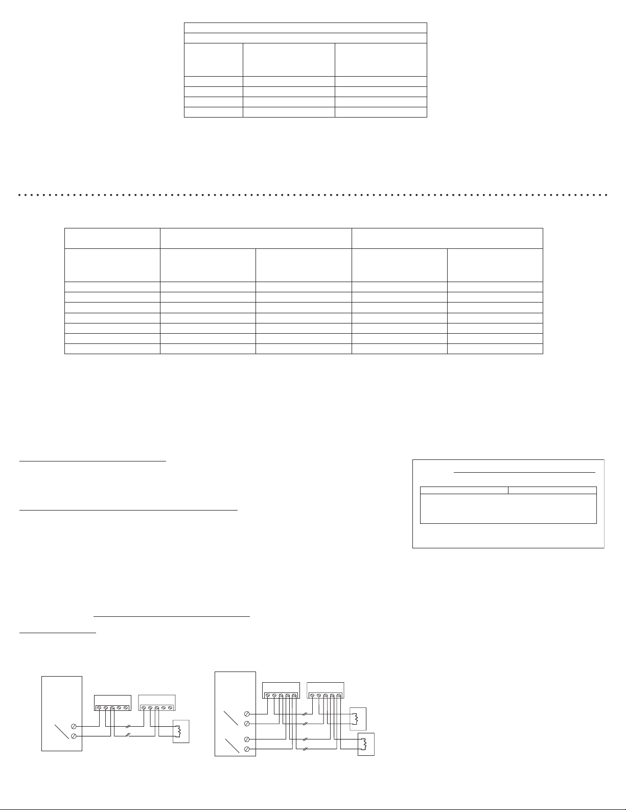
wCheck all wiring connections to make sure the signal detection circuits are not reversed or shorted together. Check wire color codes and traces.
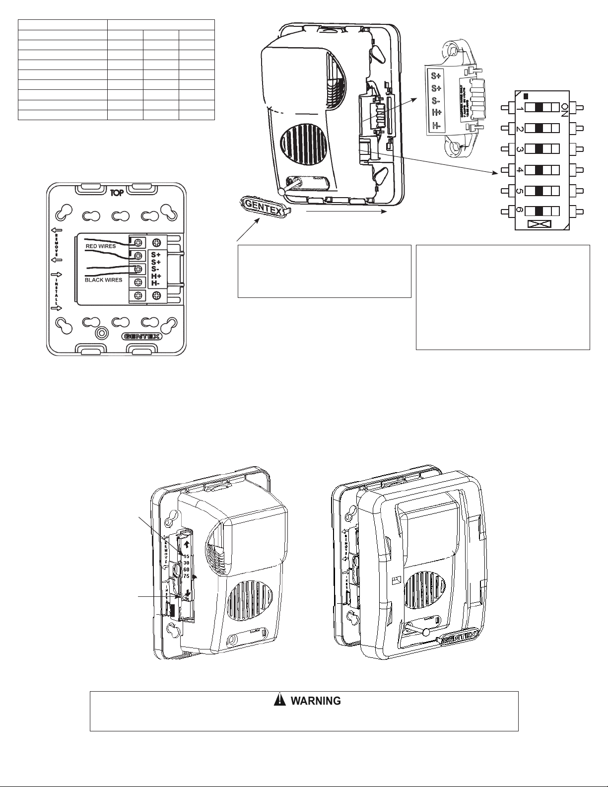
wVerify that the jumpers and switches are properly set on both the control module and signal appliance. If the jumper on the AVSM is removed, the horns will
not produce any sound unless there is an input to the H+ and H- terminals on the control module.
3. To test the signal appliances, trip the auxiliary panel or activate the alarm circuit at the main control panel or activate one of the fire detection units in the system.
All auxiliary signals should be activated.
4. An operational test on this product should be conducted in accordance with National Standards or at a minimum annually and more often if dictated by local and
state codes or authorities having jurisdiction.
NOTICE: THESE TESTING PROCEDURES AND TROUBLESHOOTING INSTRUCTIONS ARE GENERALIZED. PLEASE REFER TO THE SYSTEM CONTROL PANEL OPERATING
INSTRUCTIONS FOR PROPER OPERATION OF THE PANEL AND FIRE DETECTION SYSTEM.
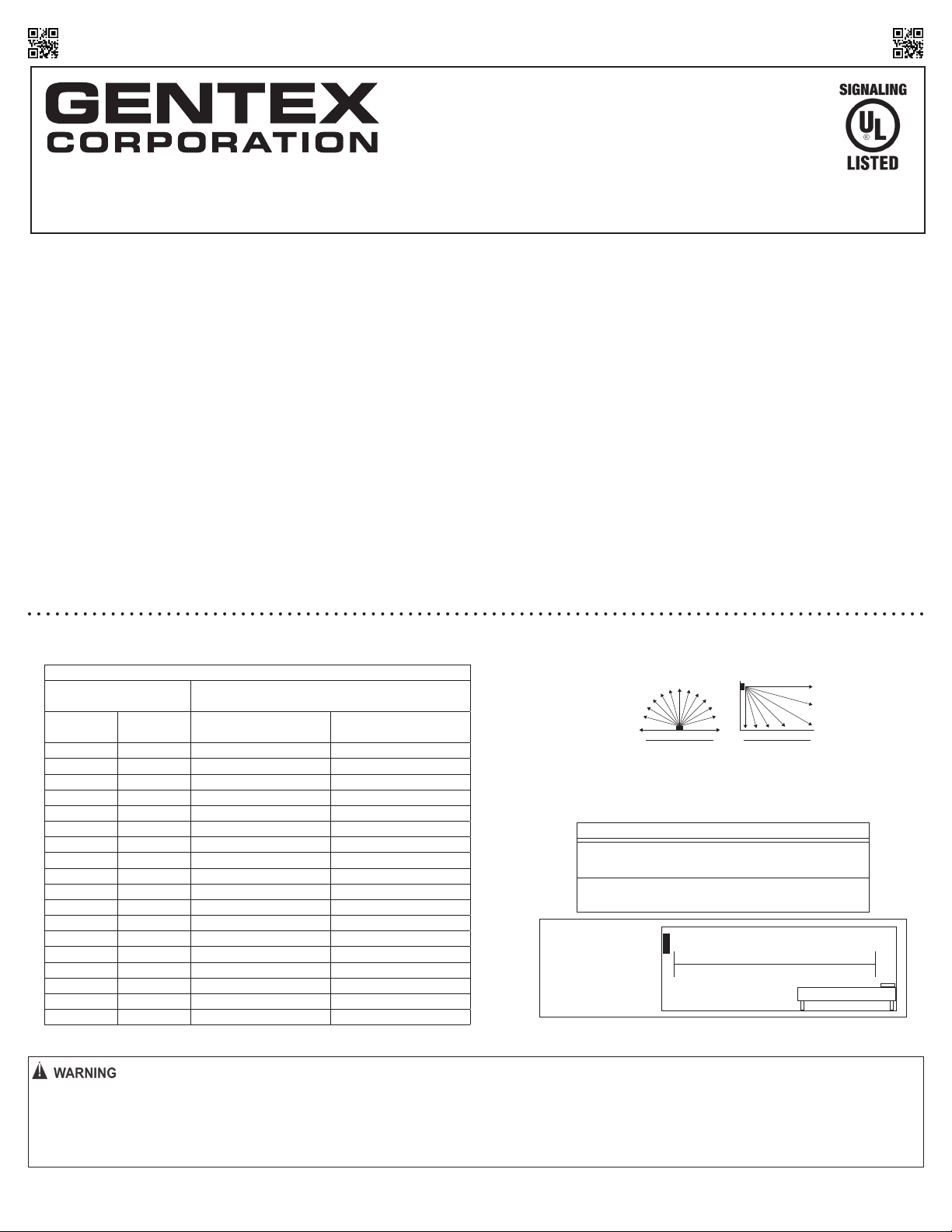
SIGNALING APPLIANCE LIMITATION:
Your horn and horn/strobe meet or exceed the current audibility requirements of ANSI/UL 464. However, if the appliance is located outside a bedroom it may not wake up
a sound sleeper, especially if the room door is closed or only partially open.
VI. TO RETURN AN APPLIANCE
Should you experience problems with your appliance, proceed as follows:
1. Turn off electrical power to the auxiliary alarm circuit.
2. Remove the bezel, nameplate, then mounting screw and slide signal off from bracket
3. Replace unit that was removed to restore wiring supervision and to eliminate system trouble alert.
4. Carefully pack the defective unit (the manufacturer cannot be responsible for consequential damage due to shipping or mis-handling). Include a return address
and complete details as to the nature of the difficulties being experienced and date of installation.
5. Return to: Gentex Corporation, 9001 Riley Street, Building 10, Zeeland, Michigan 49464. Prior to returning, call Gentex at 1-800-436-8391 or e-mail
Page 4
550-0636-AAB
Manual Issue Date:
11/01/14
GENTEX CORPORATION - CORPORATE HEADQUARTERS
600 NORTH CENTENNIAL STREET, ZEELAND, MI 49464
PHONE: 1-800-436-8391/ 616-392-7195
www.gentex.com
LIMITED WARRANTY
For a period of 36 months from the date of purchase or a maximum of 42 months from the date of manufacture (or as long as required by applicable law), Gentex warrants to you the original purchaser that the appliance
described in this product information booklet will be free from defects in workmanship and materials under normal use and service.
This warranty does not apply and is void if damage or failure is caused by: accident, abuse, misuse, abnormal use, faulty installation, liquid contact, fire, earthquake or other external cause; operating the appliance
outside Gentex’s published guidelines; or service, alteration, maintenance or repairs performed by anyone other than Gentex. This warranty does not transfer to subsequent owners or purchasers of this appliance. This
warranty also does not apply to: consumable parts, such as batteries; cosmetic damage, including but not limited to scratches or dents; defects caused by normal wear and tear or otherwise due to the normal aging of the
appliance, or if any serial number has been removed or defaced from the appliance.
TO THE EXTENT PERMITTED BY LAW, THIS WARRANTY AND THE REMEDIES SET FORTH HEREIN ARE EXCLUSIVE AND IN LIEU OF ALL OTHER WARRANTIES, REMEDIES AND CONDITIONS, WHETHER ORAL, WRITTEN, STATUTORY,
EXPRESS OR IMPLIED. GENTEX DISCLAIMS ALL STATUTORY AND IMPLIED WARRANTIES, INCLUDING WITHOUT LIMITATION, WARRANTIES OF MERCHANTABILITY AND FITNESS FOR A PARTICULAR PURPOSE AND WARRANTIES
AGAINST HIDDEN OR LATENT DEFECTS TO THE EXTENT PERMITTED BY LAW. TO THE EXTENT SUCH WARRANTIES CANNOT BE DISCLAIMED, AND TO THE EXTENT PERMITTED BY APPLICABLE LAW SUCH IMPLIED WARRANTIES SHALL
APPLY ONLY FOR THE WARRANTY PERIOD SPECIFIED ABOVE. PLEASE NOTE THAT SOME STATES (COUNTRIES AND PROVINCES/TERRITORIES) DO NOT ALLOW LIMITATION ON HOW LONG AN IMPLIED WARRANTY (OR CONDITION)
LASTS. SO THE ABOVE LIMITATION MAY NOT APPLY TO YOU. EXCEPT AS PROVIDED IN THIS WARRANTY AND TO THE EXTENT PERMITTED BY LAW, GENTEX WILL NOT BE LIABLE FOR ANY DIRECT, SPECIAL, INCIDENTAL OR
CONSEQUENTIAL DAMAGES RESULTING FROM ANY BREACH OF WARRANTY OR CONDITION, OR ARISING IN CONNECTION WITH THE SALE, USE OR REPAIR OF THE APPLIANCE, OR UNDER ANY OTHER LEGAL THEORY, INCLUDING
BUT NOT LIMITED TO LOSS OF USE, LOSS OF REVENUE, LOSS OF ACTUAL OR ANTICIPATED PROFITS, LOSS OF THE USE OF MONEY, LOSS OF BUSINESS, LOSS OF OPPORTUNITY, LOSS OF GOODWILL, AND LOSS OF REPUTATION. THE
MAXIMUM LIABILITY OF GENTEX SHALL NOT IN ANY CASE EXCEED THE PURCHASE PRICE PAID BY YOU FOR THE APPLIANCE. PLEASE NOTE THAT SOME STATES (COUNTRIES AND PROVINCES/TERRITORIES) DO NOT ALLOW THE
EXCLUSION OR LIMITATION OF DIRECT, INCIDENTAL OR CONSEQUENTIAL DAMAGES, SO THE ABOVE LIMITATION OR EXCLUSION MAY NOT APPLY TO YOU.
If a defect in workmanship or materials causes your appliance to become inoperable within the warranty period, you must return the appliance to Gentex postage prepaid to: Gentex Corporation, 9001 Riley Street, Building 10,
Zeeland, MI 49464. You must prove to the satisfaction of Gentex the date of purchase of your appliance. You must also enclose a return address. Warranty service may only be performed by Gentex personnel at Gentex’s facilities
in Zeeland, Michigan. You must also pack the appliance to minimize the risk of it being damaged in transit. If we receive an appliance in a damaged condition as the result of shipping, we will notify you and you must seek a
claim with the shipper.
If you submit a valid claim to Gentex during the warranty period, Gentex will, at its option, repair your appliance or furnish you with a new or rebuilt appliance without charge to you except for postage required to
return the appliance to us. Gentex will not reimburse you for repairs or replacement parts provided by other parties. Your repaired or replacement appliance will be returned to you free of charge and it will be covered
under the warranty for the balance of the warranty period, if any. When a product or part is replaced, any replacement item becomes your property and the replaced item becomes property of Gentex. For additional
warranty and product information go to www.gentex.com.
THIS WARRANTY GIVES YOU SPECIFIC LEGAL RIGHTS AND YOU MAY ALSO HAVE OTHER RIGHTS WHICH VARY FROM STATE TO STATE (OR BY COUNTRY OR PROVINCE). BY THIS WARRANTY, GENTEX DOES NOT LIMIT OR
EXCLUDE YOUR RIGHTS EXCEPT AS ALLOWED BY LAW. TO FULLY UNDERSTAND YOUR RIGHTS, YOU SHOULD CONSULT THE LAWS OF YOUR COUNTRY, PROVINCE OR STATE.
This manual suits for next models
2
Other Gentex Safety Equipment manuals