GENUV GUVx-T1XC-3LW Series Instructions for use

Technical Note
1. Features of LW probes.
- UV measuring in water
- Custom products can be supplied.
- Output type : DC 0~5V or 4 –20mA Current output
- NIST, KRISS traceable calibration possible
2. Applications
- Monitoring Water treatment system
- DVGW probes for ballast water system
- UV lamp monitoring
3. The features and advantages of the product
- High reliability (It can be use 10bar pressure)
- Highly visible barrier: pure ultraviolet light (UVA, UVB,UVC)
sensors using. No need for a separate filter
- Custom Product supply available to meet customer orders
- Calibration Service offers tailored to customers' requests
-Voltage of Analog type (0 ~ 5V) or current (4-20㎃) can
provide
- Built-in temperature sensor available
- excellent corrosion resistance STS314-L Material
- Reliable implementation at an affordable price
4. Advantage of using a UV sensor probe
- Can accurately measure the illuminance values of the
Chamber inside
- UV lamp intensity control based on measure intensity
- Can be monitored ON / OFF status of a UV lamp
- UV light can be seen for lamp replacement time.
Probe Application Guide lines for Water treatment
GUVx-T1XC-3LWx
GUVx-T11GC-I8LWx
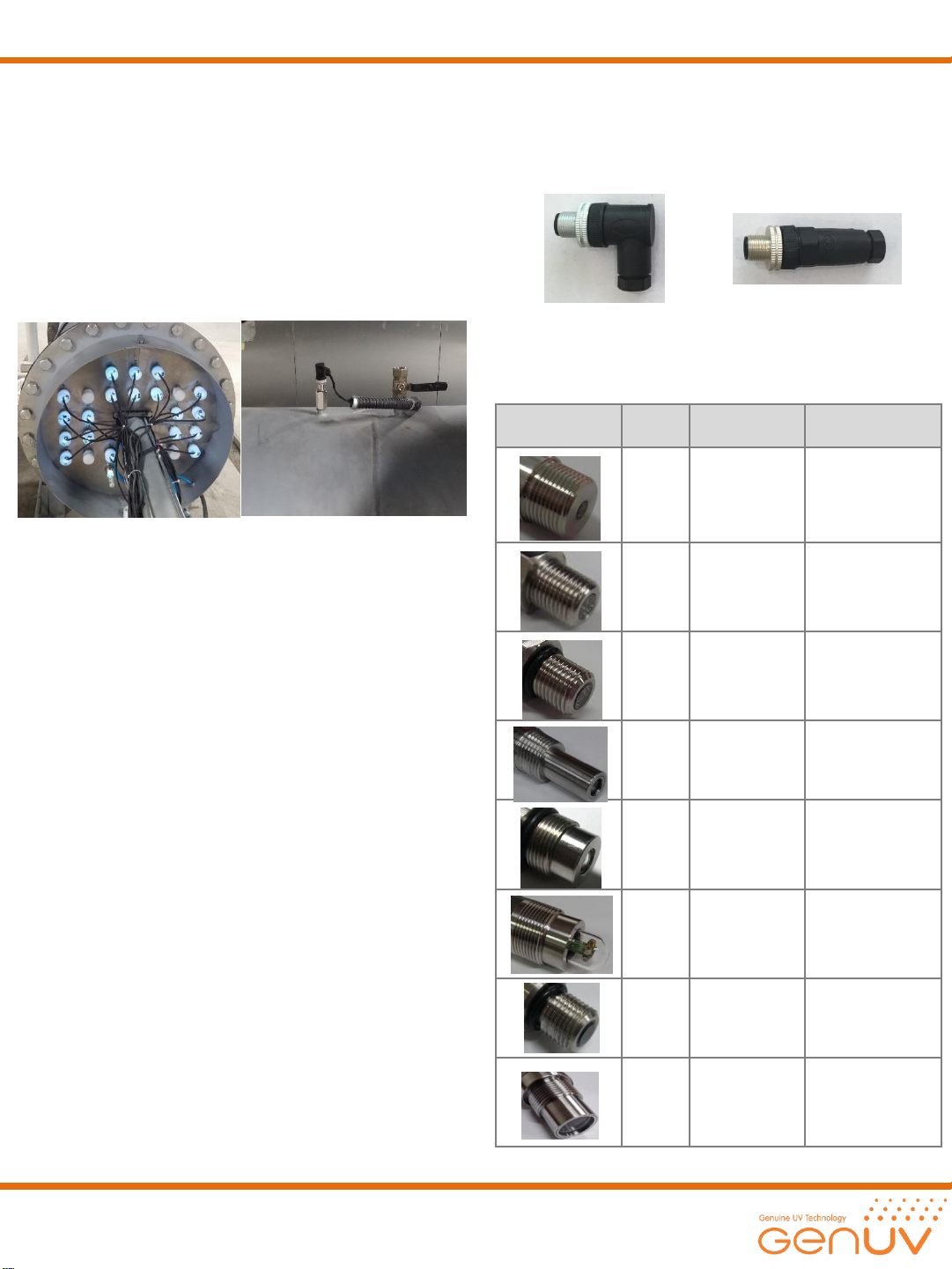
Water treatment systems operating examples
•Connector type
- install by adopting a form suitable for the installation
Environment.
‘L‘ Angled connectors ‘I' shaped connector
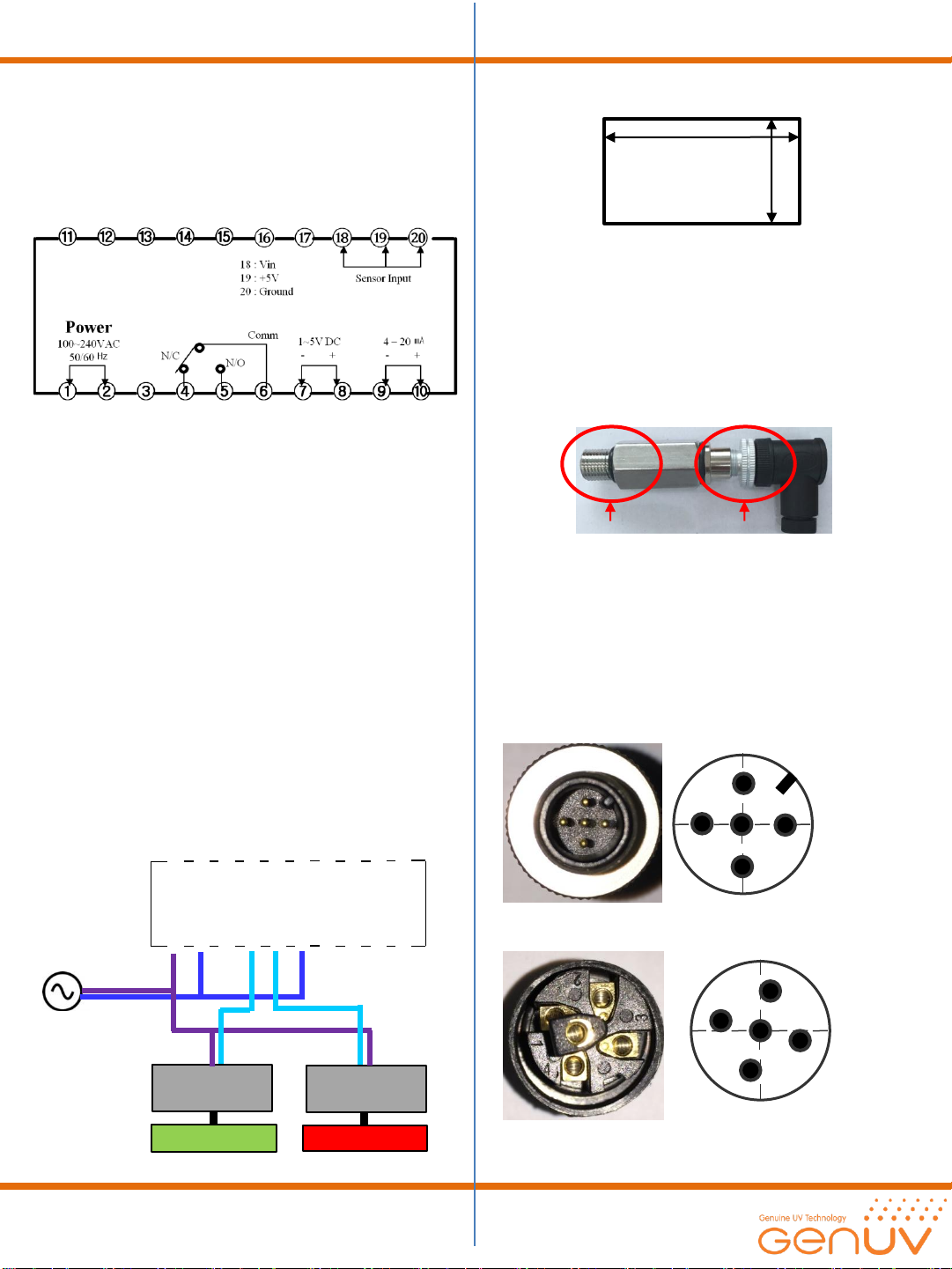
• Fixing Hole Specifications
Product photos
Product
Name
Fixing Hole
Specifications
Recommendation
LW10
PT3/4", 16 ㎜
Chamber type
LW5
PT 1/4", 12 ㎜
Chamber type
LW5.1
PF 1/4", 12 ㎜
Chamber type
LW8
NPT1/2", 12 ㎜
Chamber type
LW9
PT3/4", 11 ㎜
Chamber type
LW11
PT 1 1/4", 21
㎜
Chamber type
LW13
PF 1/4 "/12 ㎜
Chamber type
DVGW
G1” 34mm
A high-pressure
mercury lamp
Chamber type
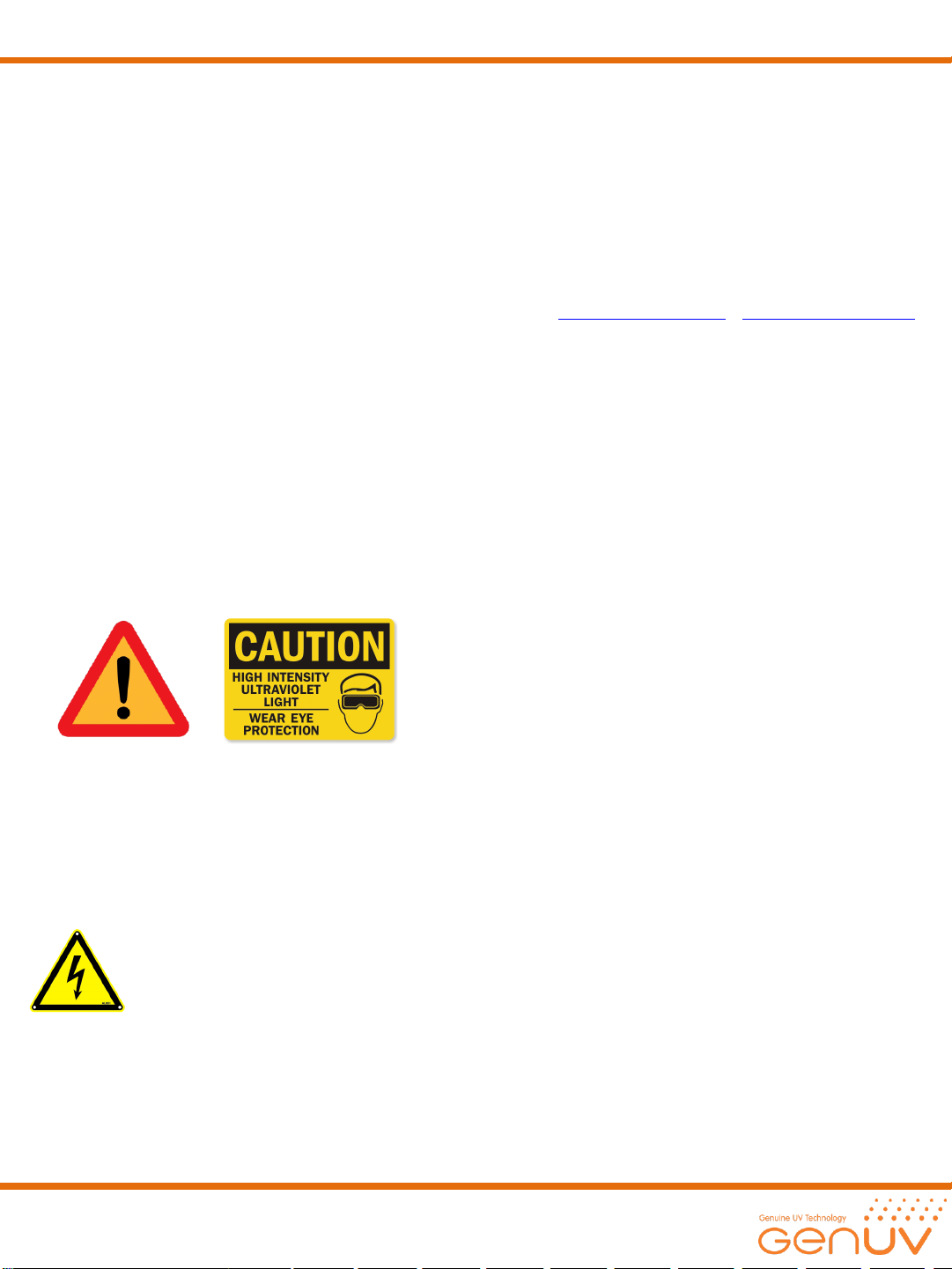
5. Point that must be taken into account in product
selection
- Consider the thread type of Socket that you try to install.
- Select maximum detection power range.
- Select the required output Type (0 ~ 5V, 4 ~ 20mA)
- Check the operating voltage (5V or 24V)
- In the case of current output (4-20mA), operating voltage
9~24V only possible selection.
- The chosen shape and length of the Connector
- Wire type selection: in case of the current output (4-20mA),
and can be selected from among 2 Wire and 3wire
- Length 5m Connection default and possible adjustment
according to customer's request
(Voltage output type is available up to 10m)

7. precautions Sensor probe design in the Chamber
- Incident angle of LW series are not exceed 30 degrees.
So We recommend to install the probe vertically
- With more than 85 °C the temperature of the product's
installation conditions or pressure does not exceed 10 bar
in an environment should be used.
- Check the thread sizes and Sensor Probe Socket type of
installation you want.
8. Product Installation examples
1) Selects a suitable Probe to install Socket.
2) And selecting a position to incident perpendicular to the
UV lamp.
3) 3-4 times a hoist and install the Teflon tape to the threads
when installing the UV chamber.
4) Connect Check the wiring connection terminals
If you connect wrong polarity it will cause the module
damaged or broken.
UV LAMP
90˚
UV sensor probe
Chamber
6. difference between PF screw and PT screw
PF parallel screw + socket PT inclined screw + socket
- PF is the sockets are sealed with O-ring is pressed into the
end Because PF is parallel screw thread.
5) Install position
UV chamber
UV Lamp
90˚
-Please install the Sensor probe to the middle of the UV lamp.
Because incident angle of UV sensor is narrow.
Sensor probe socket
Installation example
9. Wiring connections
1) Verify that there are no longer such a chamber leaks after
installing the Sensor probe
2) Insert Sensor probe to determine the direction of the
Connector.
3) To connect the wiring, check the connection terminals.
The color-coded terminals are available as follows.
insert direction
4) black lines and white lines (GND) is connected to the
Sensor probe interior.
5) example how to connect
color
terminals
Remark
Red
VCC
(5V or 24V)
Black
GND
Green
Vout or Iout
Reference
Certificate of
Quality
White
GND

Red : Vcc 5V or 9~24V
Black : Gnd
Green : Vout or Iout
White : Gnd
∙ If you connect wrong polarity it will cause the module
damaged or broken.
∙ Black lines and white lines are connected (Short) internally.
PLC or Multimeter
Power Supply
• GUVD-MG02S connections
- GUVD-MG02S Diagrams (Vout)
1)Connect AC power to #1 and # 2 , and connect GND wire #5.
2) Connect red wire to #11(VCC) , Black wire to #12(GND) ,
White wire to #5(GND) , Green wire to #7(Vout)
⑪⑫⑬⑭⑮⑯⑰⑱⑲⑳
①②③④⑤⑥⑦⑧⑨⑩
90˚
Chamber
UV LAMP
System Power
AC 100~240V
+ –
Sensor Power
DC 20V Sensor Output
Max: DC 5V
+
(System GND)
–
- GUVD-MG02S Diagrams(Iout)
1) Connect AC power to #1 and # 2 , and connect GND wire #5.
2) Connect red wire to #11(VCC) , Black wire to #12(GND) ,
White wire to #5(GND) , Green wire to #6(Iout)
⑪⑫⑬⑭⑮⑯⑰⑱⑲⑳
①②③④⑤⑥⑦⑧⑨⑩
90˚
Chamber
UV LAMP
System Power
AC 100~240V
+ –
Sensor Power
DC 20V Sensor Output
4-20mA
+
(System GND)
–
⑪⑫⑬⑭⑮⑯⑰⑱⑲⑳
①②③④⑤⑥⑦⑧⑨⑩
System Power
AC 100~240V
18 : Vin
19 : +5V
20 : Ground
Sensor Input
90˚
Chamber
• Connection diagram of MG-05
-GUVD-MG05S Diagrams
1) Connect AC power to #1 and # 2
2) Connect Green wire to #18(Vout)
Red wire to #19(+5V) , Black wire to #20 (GND)

11. Panel cutting size
-GUVD-MG02S, GUVD-MG05S have same panel cutting size
92(-0,+0.5)
45 (-0,+0.5)
Panel Cut Out(mm)
13. Calibration Period
- Calibration recommended period is two years.
12. IP Grade
- LW Probe window is a waterproof rating of all products
are IP68.
- Maximum operating pressure: 10bar below
- Because of the waterproof rating is IP64 rated Sensor
probe Connector
Do not use underwater.
* LW9 Probe is available in the water. (IP68)
IP68 IP64
10. Relay operation method
1)If the abnormality is detected in the water treatment system,
It is necessary to generate an alarm.
In this case our indicator have relay alarm function
Our indicator have relay alarm function (Dry contact type)
a. Connect Ac power terminal #1 and #2 and connect sensor
cable #18 (Green wire) , #19 (Red wire) , #20 (Black wire).
b. Relay output terminal is (#4~#6), Voltage output terminal
is #7 and #8 , Current output is #9 and #10.
* Please turn off the indicator before connect output cables.
c. If you want to use relay output, Please use with #6 and #5.
- (N/O : Normal open in normal case terminal status is open
but if the signal is ON, the terminal will be closed. OR
#6 and #4N/C : Normal Close , in normal case the terminal
status is close, but if the signal is ON, the terminal will be
open)
- In normal status the relay will contact #6 and #4 and
In abnormal status the relay will close #6 and #5.
- If you use large capacity ballast, please use capacitor
(22pF/220kV) as below.
- Voltage output (DC 1~5V #7 and # 8) , and Current output
(4 ~ 20mA , #9 and10) will operate based on RP(%)power.
ex) If RP power(%) is 0% ,
Voltage output will be DC 1V
Current output will be 4mA.
ex) If RP power(%) is 100%
Voltage output will be DC 5V
Current output will be 20mA.
⑪⑫⑬⑭⑮⑯⑰⑱⑲⑳
①②③④⑤⑥⑦⑧⑨⑩
AC POWER
Red light
Green light
Red light
Ballast
Green light
Ballast
AC power
#4 : Normal close
#5 : Normal open
#6 : Comm
Fig. Wiring diagram of Green light and Red light
14. Connector Pin number
2
3
4
1 5
2
3
4
1
5
1 : GND(Black)
3 : VCC(Red)
5 : Vout or
Iout(Green)
1 : GND
3 : VCC
5 : Vout or Iout

GUVX-T1XC-3LWX
GUVX-T11GC-I8LWX
15. Checks in when the amount of light output is not
out
1) Make sure that wiring is properly wired
2) Supply voltage (5V or 24V) Check if supply is being properly
3) Check lighting of the light source (UV lamp)
4) Ensure that the connectors are not separated
5) Ensure that the UV Sensor probe is installed correctly
- It has been installed correctly towards the direction of the
UV lamp?
- No dirt or contamination on the Window of the UV Sensor
window
- If the irradiation amount of the UV lamp is not enough
- Detection Power range is set too high compared to the
amount of irradiation
ex) The maximum measurement range is 1,000㎽/ ㎠, and
when the amount of irradiation 5㎽/ ㎠less
6) The light source (UV lamp ) if it is not UVC lamp
(UVA, UVB lamp yen no reaction)
7) LW series does not respond to the sunlight or visible light
If you want the Sensor probe test will use the UVC lamp
16. Product Handling Precautions
-Do not expose your eyes and skin, UV light is very dangerous
- When handling the UV lamp you should wear safety gear
such as goggles
- If the UVC lamp is installed in an enclosed space it will be
admitted after that has adequate ventilation.
When you install the product ,
Turn off the Power source
17. A/S request in case of product failure
1) Should any failure is found in product, please call the
sales company or customer center for A/S.
2) Product warranty period is 1 year from the date of
procurement with no charge. However, failure which
caused by user’s misuse or carelessness within warrant
period or any failure after the warrant period shall be
chargeable for it’s A/S.
3) Product inquiry and on-line customer service :
uvsensor@geni-uv.com ( http://www.geni-uv.com )
This manual suits for next models
1
Table of contents
Other GENUV Measuring Instrument manuals