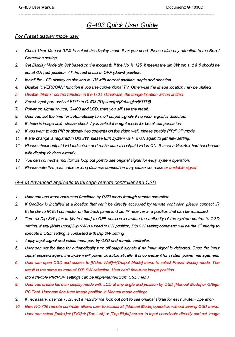
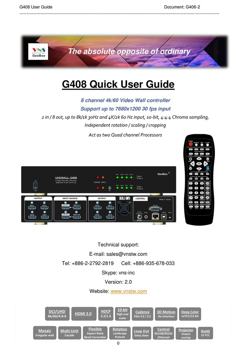
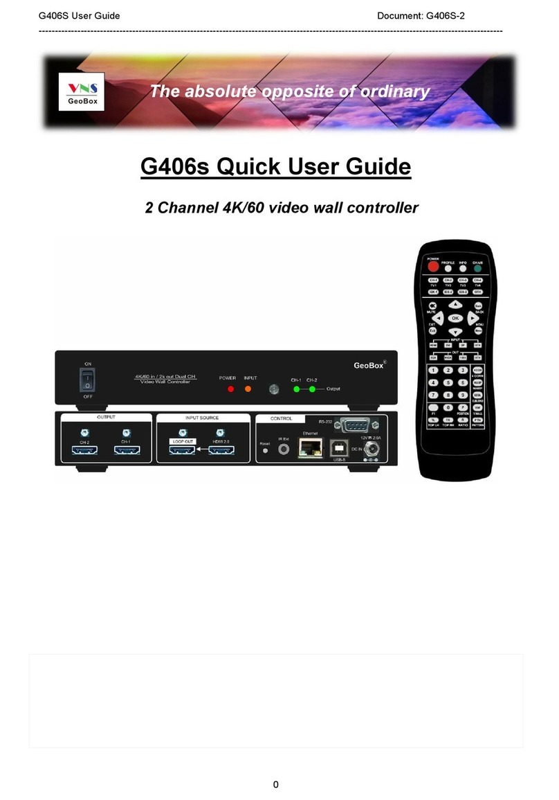
GeoBox G-403 Owner's manual

G-403-3
0
G-403 Quick User Manual
(4 screens irregular video wall controller)
Technical support:
E-mail: sales@vnstw.com
Tel: +886-2-8751-2785 ext. 301
Cell: +886-935-678-033
Skype: vns-inc
Version: 2.08
Website: www.vnstw.com.tw

G-403-3
1
Table of Contents
1 Introduction................................................................................................................................. 2
2 Features........................................................................................................................................ 2
3 Outlook and main Functions………………………………………………………………………… 4
4 How to use IR remote controller...............................……………………………………………... 4
5 How to use preset display mode..………………………………………………………………….. 5
6 Advanced application though Manual Mode........................................................................... 5
7 How to create irregular video wall...................…….….…........................................................ 6
7.1 Capture coordinates from design drawing or measurement.....................….............. 6
7.2 Capture coordinates from picture by Microsoft “Paint”............................................... 7
7.3 How to key-in coordinates.………………………………………........................................ 10
7.3.1 Load coordinates via remote controller…………………......................................... 10
7.3.2 Load coordinates via [GAlign] PC tool.................................................................... 10
8 Video wall with multiple units of G-403..................................................................................... 11
8.1 Case study A (Full HD signal source)................…………………………………………… 12
8.2 Case study B (4K signal source)..................................................................................... 12
8.3 Case study C (Video wall with 15x 55”LCD)................................................................... 13
9 Portrait display mode........................................………..…………………………………............... 13
9.1 Comparison between landscape/rotated content in portrait display............................ 14
10 Image position fine-tune.............................................................................................................. 14
11 How to determine source signal resolution for a video wall.................................................... 15
12 How to show full operation menu in signal source................................................................... 15
13 Image looping playback and LCD Burn-in Mark protection..................................................... 15
13.1 Example for looping playback settings........................................................................... 16
13.2 Procedures to create Looping playback Indexed........................................................... 16
14 How to change display aspect ratio and image position.......................................................... 17
15 EDID setting.........…………………………………………………………………………………….….. 17
16 Other notice..............……………………………………………………………………………….……. 18
Limited Warranty
This device is designed and tested to the highest standards and backed by two years‟ parts and labor warranty. Warranties are effective
upon the first delivery date to the end customer and are non-transferable. Warranty related repairs include parts and labor, but do not
include repair of faults resulting from user negligence, special modifications, abuse (mechanical damage), shipping damage, and/or
other unusual damages. The customer shall pay shipping charges when the unit is returned for repair. Manufacturer will pay shipping
charges for return shipments to customers.
Manufacturer does not assume responsibility for consequential damages, expenses or loss of revenue, inconvenience or interruption in
operation experienced by the customer. Warranty service shall not automatically extend the warranty period.
FCC/CE statement
This equipment has been tested and found to comply with the limits for a ClassA digital device, pursuant to part 15 of the FCC Rules.
These limits are designed to provide reasonable protection against harmful interference when the equipment is operated in a
residential / commercial environment. This equipment generates, uses, and can radiate radio frequency energy and, if not installed and
used in accordance with the instruction manual, may cause harmful interference to radio communications. Operation of this equipment
in a residential area is likely to cause harmful interference in which case the user will be required to correct the interference at his own
expense.

G-403-3
2
1 Introduction
VNS creative video wall controller G-403 is world unique and the first pure hardware solution that can
create all kinds of display modes through IR remote controller. G-403 has pre-defined irregular display modes
that can be selected by Dip SW. User can also create any display mode for regular, portrait and irregular video
wall using LCDs with different dimension, resolution and bezel. Conventional low cost monitor and TV can be
used as display devices. The LCD can be installed at any angle and position. User can install LCD first, then crop
the required image for each LCD by inputting the coordinates of Top Left and Top Right corners of the image by
remote controller or PC tool.
G-403 is 4 screen video wall controller with PIP/POP function and supports up to 4k/2k 30hz input. 4K/2k
loop out port is available for daisy chain connection. It can be cascaded to create large scale video wall.
Dynamic aspect ratio and position adjustment for entire video wall are special features for G-403. User has
more flexibility in how to show the content on different shapes of video wall. User can also select different
background color in video wall blanking area if the content is not at full screen. Looping playback is another
feature to allow user to setup up to 10 display modes from the same display content and looping playback with
selectable time interval. This function can be used to highlight specific image region to show special effect on the
video wall dynamically from the same content.
G-403 is designed with highest industrial standard for 7/24 working environment. It provides a simple,
flexible and reliable solution for creative video wall.
2 Features:
1. Flexible video source connection
3 input ports to support HDMI, DVI, DP, VGA and YPbPr input signals up to 4k/2k @30Hz resolution.
2. Quad channel outputs:
4 x HDMI outputs for connecting with 4x LCD or conventional TV/monitor without matrix control.
3. System cascade display
One 4k/2k HDMI loop out port for multiple units cascade in large scale video wall. No HDMI splitter is
required.
4. Pre-defined display modes
37 pre-defined creative display modes that can be selected by Dip SW on front panel.
5. Create irregular video wall by user
User can create any display mode for regular, portrait and irregular video wall using LCDs with different
dimension, resolution and bezel. Use can crop the required image for each LCD through inputting the
coordinates of Top Left and Top Right corners of the image cropped for each LCD by remote controller or
simple PC tool.
6. Anyplace cropping
User can crop any image location and assign to any LCD.
7. Flexible aspect ratio control
Flexible aspect ratio control across entire video wall through OSD menu is integrated. The adjustment

G-403-3
3
range is from 25% to 200%.
8. Flexible position adjustment
The combination of flexible aspect ratio control and position adjustment function (25% to 200%) will
allow user to determine the best image region for the display on the video wall.
9. Auto looping playback
User can setup up to 10 display modes from the same display content and looping playback with
selectable time interval (1 second to 600 seconds). This function can be used to highlight specific image
region to show special effect on the video wall dynamically from the same content.
10. Any display devices
Conventional TV/monitor can be used at top/bottom, LH/RH flip position to balance TV bezel difference
between top and bottom edges.
11. Programmable EDID: preset 23 EDID + programmable EDID setting to optimize vide quality.
Programmable EDID has below resolution range: H: 1024-3840, V: 720-2400
12. LCD burn-in mark protection: Auto image position shift to prevent LCD from burn-in mark.
13. PIP function: Picture in Picture from two selected signal sources with flexible image size (up to
1024x768), aspect ratio and position adjustment across entire video wall.
14. POP function: Image Side by Side display with full screen or maintain original aspect ratio. Two POP
contents can be displayed on LCDs at landscape or portrait position at side by side or top-bottom.
15. Auto power on/off control: When no input signal is detected, GeoBox can auto-turn off output signal.
Once input signal is detected, it will auto-turn on GeoBox and send out signal again. It is convenient for
system power on/off control.
16. Selectable background color: When adjusting aspect ratio, user may see some blank background in
the video wall. User can select background color by OSD.
17. Custom settings: Up to 10 different display modes settings can be stored and recalled at any time.
18. No video splitter, PC or software is required. More reliable.

G-403-3
4
3 Outlook and main functions
Note: After finishing DIP SW setting, Power OFF and ON again is required to execute the settings.
4 How to use IR remote controller
RC-700 remote controller
Procedures for determine each LCD position
1. Select manual display mode saved location—IDX1~IDX10 (Repeat IDX4
will circulate between IDX 4 to IDX 10)
2. Select output port—TV1~TV4
3. Click Top Left [TL] and input coordinates
4. Click Top Right [TR] and input coordinates
5. Click [F1] and adjust image position if necessary
6. Adjust aspect ratio if necessary: [R]
7. Adjust image position if necessary: [P] (after aspect ratio change)
8. No special input sequence is required among TV1~TV4.
Output port selection (TV1-TV4)
Store location for manual setting display modes (IDX1-IDX10)
Video wall Main Menu (VW)
Entire video wall position adjustment (P)
To adjust image position at H&V without changing image size (F1)
Entire video wall Aspect Ratio adjustment (R)
Top Right coordinate menu (TR)
Top Left coordinate menu (TL)

G-403-3
5
5 How to use preset display mode
a、Check User Manual and select display mode # as you need. User can also open [Video Wall][Output
Mode] OSD menu and select preset mode # (showed at OSD bottom right position)
b、Set Display Mode dip SW based on the modes #. If the No. is 125, it means the dip SW pin 1, 2 & 5
should be set at ON (up) position. All the rest is still at OFF (down) position.
c、Install the LCD display as showed in User Manual with correct position, angle and direction. User can‟t
fine-tune image position in each LCD. Source content will be fit into entire video wall and may have
different aspect ratio. User can adjust aspect ratio through Video Wall [Overlap] function.
d、Disable „OVERSCAN” function to get correction image position if you use conventional TV.
e、Disable „Matrix” control function in the LCD. Otherwise, the image location will be shifted.
f、Select input port and set EDID in G-403 ([Options][Setting][EDID])..
g、Power on signal source, G-403 and LCD, then you will see the result.
h、User can set the time for automatically turn off output if no input signal is detected. ([Options]
[Accessibility][Standby Time]“30”)
i、If image shift is found, please check if you select the right mode for bezel compensation.
j、If PIP or side by side display is required, please enable PIP/POP mode.
k、If any change is required in Dip SW, please turn on the system again to get new setting.
l、Check input/output LED indicators and make sure all input/output LED is ON. It means GeoBox had
handshake with signal source and display devices.
m、You can connect a monitor via loop out port to see original signal for easy system monitoring and
operation.
n、Please note that poor cable or long distance connection may cause dot noise or unstable signal.
6 Advanced application through Manual Mode
a、User can use more advanced functions by OSD menu through remote controller or GAlign PC tool.
b、If GeoBox is installed at a location that can‟t be directly accessed by remote controller, please connect
IR Extender to extend control distance.
c、Turn all Dip SW pins in [Main Input] to OFF position to switch system control authority to OSD setting. If
any [Main Input] Dip SW is turned to ON position, Dip SW setting command will be the 1st priority to
execute when the system has been powered on.
d、Apply input signal and select input port by OSD through remote controller.
e、User can open OSD and access to [Video Wall][Output Mode] menu to select Preset display mode.
The result is the same as DIP SW selection. User can‟t fine-tune image position.
f、More flexible PIP/POP settings can be implemented from OSD menu. PIP/POP can be applied to both
Preset mode and Manual Mode.
g、User can create his own display mode with LCD at any angle and position by [Manual Mode] or GAlign
PC Tool. User can fine-tune image position in Manual mode settings.
h、If necessary, user can connect a monitor via loop out port to see original signal for easy system
operation.

G-403-3
6
i、RC-700 remote controller allows user to access all [Manual Mode] operation without seeing OSD menu.
User can select [Index][TV#][Top Left] or [Top Right] corner to input coordinate directly and set
image position. [F1] shortcut key in remote controller allows user to adjust each LCD image H&V
position without affecting image rotation angle and size. It is convenient for image position fine-tune.
j、After finishing OSD operation, please save the result in [Profile] menu.
k、When operate [Video Wall] setting, user may see frame tear in the display. It will disappear after you
power on the system again.
7 How to create irregular video wall
User can capture Top Left and Top Right corner coordinates in each LCD and input to G-403 to build
complete video wall.
7.1 Capture Coordinates from design drawing or measurement
a、User can create all kinds of display modes for regular, portrait and irregular video wall with different size,
resolution and bezel LCDs at any angle and position through input the coordinates of two corners (Top
left and Top Right) in each LCD.
b、4 LCD as one display unit in each G-403 and can be cascaded with multiple units without number
limitation. The display panel shall be at 16:9 aspect ratio. If non-16:9 aspect ratio LCD is used, it can be
customized by factory.
c、User can convert project design drawings into 1920x1080 coordinates and pick up the coordinates at Top
Left and Top Right corners in each LCD, then input to G-403 through OSD or GAlign tool to get the result.
The Original Point for the coordinate system is set at Top Left corner as (0, 0).

G-403-3
7
d、Please note that the coordinate system (1920*1080) in H&V directions should have the same scale. In
below example, user measured horizontal active display area with dimensions of 382.5cm. The vertical
dimension is determined by 382.5/16*9=215.2cm. Some blanking borders will appear. Please put “Video
Wall” at the center position to get more flexibility for aspect ratio and position adjustment.
e、In above example, based on measuring dimensions or design drawing to determine the coordinates for
TV1 and TV2:
TV1 coordinate for Top Left corner=(0, 586),Top Right corner=(366, 216)
TV2 coordinate for Top Left corner=(815, 635),Top Right corner=(447, 286)
f、Please pay attention to the display direction of the TV
7.2 Capture coordinates from picture by Microsoft “Paint”
User can also install the LCD first, take a picture of the LCD layout and open the photo with Microsoft
“Paint” (or any other PC software that can show image coordinates such as RealWorld Paint or
PhotoShop), trim active display area image and resize to 1920x1080 resolution, collect Top Left and Top
Right coordinates for each LCD, then input these coordinates into G-403 to get the result.
Please see YouTube at below: https://youtu.be/xc1D342Wa9g
Example: 6x LCD video wall with 2x G-403. User can connect any LCD to any G-403 output.
a、To open the photo under [Paint] and trim the edge to active display area.
b、Resize the image in one edge to 1080 pixel height or 1920 pixel width and maintain aspect ratio. (It
depends on the video wall aspect ratio. The final resolution should be under 1920x1080)

G-403-3
8
c、Open [File][Properties] and resize the image to 1920x1080 resolution

G-403-3
9
d、Make sure the final resolution should be 1920*1080. Select [All], then move the image to the center of
1920x1080 coordinates by keyboard arrow key.
e、Click Top Left and Top Right corner in each LCD to collect the coordinates for each LCD. User can enlarge
the image to get more accurate result.

G-403-3
10
7.3 How to key-in coordinates
Two ways to key-in coordinates into G-403:
To key-in directly from IR remote controller
To key-in through GAlign PC tool.
7.3.1 Load coordinates via remote controller
7.3.2 Upload coordinates via [GAlign] PC tool
a、Below is PC tool (GAlign) for user to load coordinates of each LCD through RS232 port. Please key-in
the coordinates for [Top Left] & [Top Right] corner in each TV (LCD) then press [Write] to save the
settings and execute the result to G-403. The result will be the same as manual upload via OSD.
b、To enable [Diagram], user can see the result on GAlign window.
c、User can enable [Real Time] mode and use [Shift Mode], [Top Left & [Top Right] menu to fine-tune image
position. Then close [Real Time] mode and click [Write] to execute the result.
d、User can also set H&V aspect ratio and position shift through [Warp Ratio] and [Warp Position].
e、GAlign can read back the settings on the screen and modify in PC. This is good for the application while
user can‟t see the OSD menu on the screen due to irregular array.
f、User can execute looping playback function for the Indexes which have minor position difference among
them. It will prevent from Burn-in Mark on the LCD.
g、User can save data in GeoBox Profile, in PC as backup or copy to another G-403.
Procedures to key-in coordinates into G-403:
1. Select manual display mode storage location—Index1~Index10
2. Select output port—TV1~TV4 (LCD)
3. Click Top LH to key-in Top Left coordinates (X, Y) by direction keys.
User can see (X, Y) number on the OSD.
4. Click Top RH to key-in Top Right coordinates.
5. Click [F1] to do image H&V position fine-tune in each LCD.
6. Select [R] to adjust entire video wall aspect ratio if necessary
7. Select [P] to adjust entire video wall display position if necessary
Output port selection (TV1-TV4)
Store location for manual setting display modes (Index1-Index10)
(OTH : to select Index 4-10)
Video wall Main menu
Entire video wall position adjustment
To adjust image position at H&V without changing image size
Entire video wall aspect ratio adjustment
Top Right coordinate menu
Top Left coordinate menu

G-403-3
11
8 Video wall with multiple units of G-403
a、If the video wall has more than 4 LCD, multiple units of G-403 is required.
b、If the signal source is 1920x1080, no matter how many LCD inside video wall system, user can connect
the signal source to all G-403 through daisy chain connection via loop out port.
c、User needs to capture Top Left and Top Right coordinates in each LCD and input to corresponding
G-403, then it can build an entire video wall.
d、If the signal source is more than 4k/2k and user wants to get higher output resolution, user needs to
crop the image into several FHD sections and assign each section to corresponding G-403. The
cropping line for adjacent G403 can be at different locations. User can use Video Wall [Zoom], [Pan]
and [Overlap] function to crop, assign and align the final position among all G-403. All of the operations
can be done through Remote Controller and OSD but not in GAlign PC tool.

G-403-3
12
8.1 Case study A (Full HD signal source)
8.2 Case study B (4K signal source)
User can apply 3840x1080 signal to above configuration to get higher resolution.
To split the video wall into two 1920*1080 coordinate systems. The coordinate system should
cover all the LCD connected by one G-403 (Max. is 4x LCD).
TV4 is inside both coordinates and user can connect TV4 with either #1 G-403 or #2 G-403
output port. User can also set #2 G-403 coordinate system only to cover TV5-TV7.
To capture the coordinated by Microsoft “Paint” or calculation from measurement dimensions
for each LCD. Then input the coordinates as previous procedures.
User needs to use G-403 Video Wall menu to set [ZOOM]: H=2, V=1, [PAN]: #1 G-403: H=1,
V=1, #2 G-403: H=2, V=2 and increase [OVERLAP] value at the same time (select RH Edge for
#1 G-403, LH Edge for #2 G-403) to let two G-403 images combine into one. This value can be
calculated through the distance apart from image center line.
Below is another example. User can use Preset mode together with [Video Wall] settings to
combine multiple units of G-403 with 4k signal source.
(0, 0)
(1920, 1080)
8x LCD required 2x G-403.
To put entire video wall into one 1920x1080
coordinate system.
Catch Top Left and Top Right Coordinated
for each LCD and assign to corresponding
G-403 to build complete video wall.
No special connection sequence required.
(1920, 0)
(0, 1080)
#1 G-403
#2 G-403

G-403-3
13
8.3 Case study C (Video wall with 15x 55”LCD)
4x G-403 to build a video wall with 15x LG 55” LCD modules
Setup procedures: to install LCD panel firsttake photocollect coordinates from photo by
Microsoft [Paint]input coordinate for each LCD.
Fine tune the position by remote controller with [F1], [Top Left] & [Top Right] hot keys.
Adjust video wall image to expected location through [R] (Ratio) and [P] (Position) hot keys in
remote controller.
Power on G-403 again to finalize the settings to avoid frame tear in the image, then save final
settings in [Profile] for permanent storage.
9 Portrait display mode
If the display is at portrait position, user can apply the same procedures as above to build the video wall.
User can also rotate the video wall at 90/270 degrees and collect the coordinates to build the system to get
higher output resolution and better video quality. After installation, user needs to apply 90/270 degrees
rotated content or to apply GeoBox 90/270 rotation function to get correct display.

G-403-3
14
9.1 Comparison between landscape/rotated content in portrait display
If required video wall is at portrait position as below (3x landscape LCD stacked at vertical position), the
video wall aspect ratio is around 16: (9x3)=16:27 (H:V). User has two choices:
a、User can apply the content with 720*1080 (16:27) resolution to get non-distortion image with total
video wall vertical resolution at 1080.
b、User can also apply a content with 1823x1080 (27:16) resolution and rotate the content at 90/270
degrees in PC or media player. The final resolution will be 1823x1080:1080x720=2.53x higher.
c、G-403 can handle both cases no matter the content has been rotated or not. However, user will get
higher resolution image if the content can be pre-rotated.
10 Image position fine-tune
a、Please apply video wall test pattern and check if further position adjustment is required or not. Test
pattern can be downloaded from our website (www.vnstw.com).
b、For simple video wall array, user can use remote controller [F1], Top Left] and [Top Right] hotkeys to
do fine tune without seeing OSD. [F1] key will provide [Shift] function to do image position
Rotate Video Wall at Landscape direction
Collect coordinates to build video wall
Rotate content through G-403 to show
normal imageDone

G-403-3
15
adjustment for each LCD in H&V directions without change the image rotation angle and size.
Please figure out the coordinates in the Top Left and Top Right corners and adjust the coordinates if
necessary.
c、For large video wall or irregular array, it will be more convenient and easier to use GAlign PC tool for
image position fine-tune. Please use enable [Real Time] mode and use [Shift Mode] or [Top Left] &
[Top Right] command to change image position & size.
d、Starting fine-tune from video wall center position, then extend to outside area. User need to apply
test pattern for easy fine-tune.
e、After finishing adjustment in PC Tool, please disable [Real Time] mode and save the final result into
[Index #] and GeoBox through [Write] command.
f、In multiple G-403 application, user can adjust LCD position in each G-403 separately, then use
[Video Wall] setting to combine them together. User can also combine all G-403 image together first,
then adjust each LCD image position.
g、Please save the final result in [Profile].
11 How to determine source signal resolution for a video wall
a、The feeling of the video image quality is related to many factors. The final display video pixel pitch and
watching distance are two major factors in video wall.
b、If user applies FHD signal source for a 5x5 video wall with 55” LCD, the source image pixel pitch is
1220mmx5/1920=3.1mm. If the watching distance is more than 3m, the video quality is acceptable.
Above this dimension, user needs to apply 4k/2k signal source. If watching distance can be 5m, user
can apply one FHD signal to a video wall up to 8x8 matrix with 55”LCD (5mm x1920 =9.6m in width).
c、If 4k/2k signal source is applied, all the devices between signal source and LCD display should also
be able to processing or deliver the signal more than 4k/2 to achieve high quality video image.
d、Multiple G-403 can process and deliver 4k/2k image with highest video quality.
12 How to show full operation menu in signal source
a、After the complete setup, user may be difficult to see the menu or PC Desktop for operation in
irregular video wall. User has below choices to see full screen image in LCD for further operation:
To connect G-403 Loop out port with one monitor to see full screen image.
Click Remote control Index key [OTH] to activate default setting to see full image in each LCD.
To turn on front panel [Main Input] Dip SW and turn off all [Display Mode] Dip SW, then Power on
G-403 again to enable full image in each LCD.
After finish necessary operation, user needs to return to required settings to get desired display.
b、Please set signal source with “Auto-Run” so that end user can power on the signal source and the
system will run automatically.
13 Image looping playback and LCD Burn-in Mark protection
a、User can create up to 10 display modes (Indexes) and execute looping playback with selectable
time interval and display modes.

G-403-3
16
b、The display mode can show different display settings in each LCD, including different size, image
location & rotation angle. Different aspect ratio and display position in entire video wall can be put
into different display modes as well.
c、One of the applications is that user can display a product at different rotation angle or zoom in/out
the product to see different feelings. User can also display a series of products on the screen and
pop up each product at different time interval.
d、If user applies two same display modes in looping playback, the switching time interval will be also
double.
e、By the same concept, user can slightly shift the image at some time interval to prevent burn-in mark
in LCD. This is important for a still image display on the LCD.
13.1 Example for looping playback settings:
a、Please check YouTube Video at: https://youtu.be/4Gc0KcuX27g
b、Description: 4 LCD installed at different directions.
c、Looping Range: 5 (5 indexes), Looping Time: 1 second
d、Index settings:
Index 1: factory default settings, 4 independent images with the same content at different
direction
Index 2: to put TV1 into 1/4 of the [All in One] image
Index 3: to put TV1 & TV2 into 2/4 of the [All in One] image
Index 4: to put TV1 &TV2 & TV3 into 3/4 of the [All in One] image
Index 5: to combine TV1, TV2, TV3 and TV4 into one complete [All in One] image
13.2 Procedures to create Looping playback Indexes
a、To set coordinates for TV1-TV4 to become one complete image.
b、To save the same settings into Index 2- Index 5
Index1
Index 2
Index 3
Index 4
Index 5
Index 1

G-403-3
17
Select Index 2 and click [Write] command.
Select Index 3 and click [Write] command.
Select Index 4 and click [Write] command.
Select Index 5 and click [Write] command.
c、To modify the settings for each Index
Select [Index 1] and click [Reset] to reset Index 1 to show source image in all TV.
Modify Index 2 to keep TV1 setting and reset all the rest to default setting
Modify Index 3 to keep TV1 & TV2 setting and reset all the rest to default setting
Modify Index 4 to keep TV1, TV2 and TV3 setting and reset TV4 to default setting
d、To set Looping playback
Set [Loop Range]=5 (looping from Index 1 to Index 5)
Set [Loop Time]=1 (for 1 seconds interval)
e、Save to Profile 1 & 5 (Profile 5 as Backup)
f、Power Off/On again to confirm the final settings.
14 How to change display aspect ratio and image position
a、User can change entire video wall image (4 LCD) aspect ratio from 25% to 200% at both horizontal
and vertical directions through [Warp Ratio] & [Warp Position] commands in GAlign PC tool or [Ratio]
& [Position] hotkeys in IR remote controller.
b、This function can solve image aspect ratio issue due to different aspect ratio between signal source
and the video wall. User can easily select one optimized aspect ratio as needed.
c、The above aspect Ratio and image Position changes can be saved into different display modes for
looping playback so that viewer will see more impressive video wall.
15 EDID setting
a、EDID setting will tell signal source to output optimized signal timing for video wall system. If the signal
timing can match video wall design, it will maintain best video quality with full screen without distortion.
b、23 preset EDID resolutions can be selected. User can also create EDID manually and set non-VESA
standard EDID timing in the range between 1024x768 and 3840x2400.
c、After creating the EDID, PC, laptop or media player may still can‟t output required timing due to design
limitation. In some case, user still needs to do manual output settings in signal source.

G-403-3
18
d、Firmware EDID update: While FW update, we suggest user to update EDID through below procedures:
To select any EDID timing in OSD list, after 5 seconds, return back to the EDID timing as you require.
16 Other notice
a、If the [Main Input] DIP SW is not set at OFF position, when power on the system, it will not display
previous settings. User needs to recall from [Profile].
b、Please access [Options][Accessibility][Standby Time] to enable auto shut down function. It will
auto-shut down output while no input is detected. Once detects input signal, it will turn on again.
c、User can set Box ID for independent control in each GeoBox.
851: control GeoBox ID No. 1
853: control GeoBox ID No. 3
850: simultaneous control for all GeoBox
User will see flashing LED on front panel after press 85x number keys. It means the GeoBox
with flash LED is locked and will not be controlled by remote controller.
d、Each G-403 is equipped with IR extenders. User can extend IR control distance up to 20m through
2.5mm audio cable.
e、GPM (GeoBox Parameter Manager) provides a function for user to backup or duplicate the settings
from one GeoBox to another unit. Please download from website.
f、GAlign PC tool is connected through USB to RS232 cable. GAlign PC tool is available on website.
g、OSD Lock / Unlock: When continuously press [MENU] key in IR Remote Controller for 5 seconds, the
OSD function will be locked. To press MENU key for 5 seconds again, it will unlock OSD.
h、User can set [OSD Time] at “0”to maintain the OSD for long time and not auto turn-off. Please access
by [Options][Accessibility][OSD Time]“0”.
i、Poor signal cable connection or long cable may cause noise on the display. Re-connect or replace a
new cable may solve the problem. Normal HDMI connection with good cable can be up to 15m.
j、[F1] key in remote controller can provide image [Shift] function for each LCD. It can shift image
position in H&V directions without change the image size and display angle.
k、If the video wall aspect ratio is not the same as signal source, it will create abnormal aspect ratio.
Please select right EDID to let PC output a desired resolution. For manual display modes, user can
randomly adjust H&V aspect ratio in the range from 0.25x to 2.0x.
l、Preset display mode aspect ratio adjustment: To apply different [Overlap] value under [Video wall]
menu can change the aspect ratio in both Preset Mode and Manual Mode.
m、System reset: [Options][Reset][Reset All]. In some special case, [Factory Mode] reset may be
required. Please contact us in this case.
n、Please download GAlign PC tool from website to ensure new version is adopted.
o、Please save final settings into Profile for long term reservation.
p、If using different aspect ratio LCD but not 16:9, customized setting in factory is required.
Other manuals for G-403
1
Table of contents
Other GeoBox Controllers manuals
Popular Controllers manuals by other brands

RIFT Actuators
RIFT Actuators 30 Installation, operation & maintenance instructions

Veris Industries
Veris Industries G Series installation guide

AUMA
AUMA SA 07.1 Operation instructions

LOVATO ELECTRIC
LOVATO ELECTRIC RGK600 installation manual

MYE
MYE MTVC2-FM Operation manual

SOMFY
SOMFY Animeo Motor Controller 6 AC IB+ DRM installation guide