Geosense WI-SOS 480 User manual

1
Instruction Manual
WI-SOS 480 LS-G6 Laser Node
V1.0

2
CONTENTS
Overview of the Laser node 2
Equipment provided 3
Laser node installation 4
Supports 5
Fixed mounting for vertical surfaces 5
Fixed mounting for horizontal surfaces 6
Adjustable mounting plate 7
Swivel mounting bracket 8
Vertical mounting plate (pole mounting) 10
Mounting the Laser node 11
Mounting the Laser node on a swivel mounting bracket 11
Mounting the Laser node on an adjustable mounting bracket 12
Powering the laser node 13
Laser node configuration 14
Step 1: Connect GLog Android application 14
Step 2: GLog main menu 16
Step 3: Sensors Data 18
Step 4: Radio configuration 18
Radio configuration advanced options 20
Step 5: Radio signal coverage test 21
Step 6: Test results interpretation 23
Safely closing the laser node 24
Understanding data 25
Deployment recommendations 26
Target 26
Environment 27
Other 27
Maintenance and troubleshooting 28
Pointer accessories 28
Battery lifespan and data storage 30
Data acquisition 31
Troubleshooting 32
Technical specifications 33
FAQ 36
Safety instructions 37
Laser Classification Certificate 38

3
Overview of the Laser node
This user guide explains the basic procedure for configuring and making operational the WI-SOS 480
LS-G6-Laser Node. Further technical description is available in the datasheets.
The WI-SOS 480 LS-G6-Laser Node is a low-power long-range wireless datalogger and distance meter
in a single compact box. It measures distance with a highly precise Leica Laser module. The Laser
node can also be used as a standalone logger for manual monitoring and can be configured easily
and connected with a USB cable and an Android phone.
It is designed for different applications including monitoring convergences in tunnels, on civil works,
and in underground mining, and also for continuous remote monitoring of landslides and slope
movement, in particular open pits.
Equipment provided
The WI-SOS 480 LS-G6-Laser Node is shipped with the following accessories:
● Laser node
● Antenna
● Antenna adapter
The package does not include:
● USB-OTG configuration cable
● Batteries
● Grounding connector
● Mounting support
The Laser node comprises:
1. Casing
2. RP N Female connector
3. Gore valve for protection against condensation
4. External mini USB B Female connection

4
5. Laser module case
6. Connector male RP N to RP - SMA male and aerial with RP - SMA male
See the labels in the photos below for the position of each component.
Laser node and its labelled component parts
Antenna with N-connector

5
Laser node installation
The first task of getting your WI-SOS 480 LS-G6-Laser Node up and running on your site is to install
it. There are three major factors to consider when installing the Laser node: the various supports
you might use, the mounting of the Laser node, and powering the Laser node once it is installed. We
discuss each of these three here.
Supports
The Laser node needs to be mounted on a support. Depending on the application, the Laser node
needs to be installed with a certain inclination to achieve curved surfaces and on others applications
it can be just installed aligned to the surface.
Four types of support have been designed in order to cover these applications:
● Fixed mounting for vertical surfaces
● Fixed mounting for horizontal surfaces
● Adjustable mounting plate
● Swivel mounting bracket
● Vertical mounting plate (pole mounting)
For the first three types of supports (fixed, adjustable, and swivel), supports can be attached to the
Laser node using threaded rods and chemical anchors (bonded anchors) or using torque-controlled
expansion anchors that go into the surface. Three-point mounting is the best option because it
prevents bending and torsion that can lead to unstable readings. Single-anchor mounting is more
prone to drift and disturbance. It is not recommended for long-term applications.
For long-term applications, chemical anchors are preferable because their performance is more
stable and their vibration resistance is higher. Torque-controlled expansion anchors can also be
used, but only if the mounting plate or bracket is drawn tight against the surface and cannot shift
laterally.
We recommend sourcing the chemical anchors locally because they are considered dangerous goods
for air transportation. If you want to install chemical anchors, Worldsensing can supply the
6
mounting plates with the M4 lock washers and socket screws required to attach the tiltmeter to the
mounting plate. Please contact us with questions or for additional details.
Fixed mounting for vertical surfaces
The fixed mounting does not allow any movement. It is possible to use the same fixed mounting
brackets and plates compatible with the WI-SOS 480 Wireless Tiltmeter.
Vertical mounting plate (aluminium). Wall mounting. (Anchor bolts are not included)
In this case, the laser beam is perpendicular to the vertical surface plane.
Fixed mounting for vertical surfaces, exploded diagram
Fixed mounting for horizontal surfaces
The fixed mounting does not allow any movement. It is possible to use the same fixed mounting
brackets and plates compatible with WI-SOS 480 Laser Wireless Tiltmeter.

7
In this case, the laser beam is parallel to the surface plane.
Adjustable mounting plate
For use on vertical surfaces, this support allows limited rotation in two axis with respect to the
reference surface. It can be fixed to the surface with the same bolts as the fixed mounting plate. This
support is proper for fine aiming of the laser beam.
Adjustable mounting plate for vertical surface. (Anchor bolts are not included)

8
Adjustable mounting plate
Swivel mounting bracket
The swivel mounting bracket allows swivelling around the vertical axis (+/- 90°) and a minor rotation
of the enclosure on the plate (+/- 3°). It can be mounted on a wall or on a convergence bolt with ⅜”
male thread.
Swivel mounting bracket. For a wall or a convergence bolt with 3/8". (Anchor bolts are not included)

9
Swivel mounting bracket
Swivel mounting bracket, exploded diagram

10
Vertical mounting plate (pole mounting)
In the vertical mounting configuration, the Laser node can be mounted on a pole using metallic
supports. The installation of the pole and its stability will be critical for the reliability of the readings.
Depending on the installation, a pole can be more sensitive to deformation caused by environmental
loads, such as wind, rain, snow, groundwater, or frost, than other structures.
Vertical mounting plate for pole mounting

11
Mounting the Laser node
See the images below for mounting the Laser node on a swivel mounting bracket and an adjustable
mounting plate. The process is the same for installing the tiltmeter node on a fixed vertical bracket,
so we have omitted images for that process.
Mounting the Laser node on a swivel mounting bracket
Drill the surface, place the anchor on the wall
and adjust the head of the anchor into the hole
on the plate.
Adjust the upper bolt to fix the swivel support
to the anchor.
Place the bolts inside the Laser node.
Place the aerial in the vertical position and
connect the Laser node to the Glog app and use
the Installation tools menu to focus the target
on the optimal conditions.

12
Mounting the Laser node on an adjustable mounting bracket
Take off the lateral plate from the adjustable
support by unscrewing the bolts.
Insert the bolts provided inside the holes of the
plate.
Turn the four screws inside the device.
Drill the three holes on the wall following the
instruction and screw the four bolts onto the
rectangular plate.
Adjust the right angle by moving the three
circular wheels.
Place the aerial on a vertical position and
connect the Laser node to the Dlog app. Use
the Installation tools menu to focus the target
on the optimal conditions while finally adjusting
the angle of the plate.

13
Powering the laser node
The WI-SOS 480 Laser Distance Meter Node is shipped closed and may not have batteries installed.
In order to initialise it, you should follow these steps:
1. Open the laser node (using a 2.5 mm Allen wrench)
2. Insert C-type batteries in the battery holders. One or two batteries can be placed (the more
batteries placed, the longer life the logger will have). Polarity is indicated;
Please note that the device has reverse battery protection but it is not safe to keep batteries
reversed in the laser node for a long time.
Warning: Risk of explosion if incorrect batteries are used. Dispose of batteries according to
instructions. This equipment should be installed in restricted access areas.
3. The logger can be powered with batteries and with external power, but there is no switch
available to select battery or external power.
Node information

14
Laser node configuration
Ideally, this step of the process should be carried out in the same location where the node is going
to be installed. This way, users can perform an on-site radio coverage test.
The node configuration process is done using the WI-SOS app, known as the GLog, which is
compatible with any Android device equipped with OTG technology (OS Android HoneyComb 3.1 or
higher required). WorldSensing has tested Motorola Moto G4 and G5 and ensures that they are able
to configure and test all nodes.
GLog starts up once the device has been connected to the node using the USB-OTG cable. Manual
startup is not necessary.
When a new version of the app is available, GLog will automatically display a message.
The whole configuration process does not take more than five minutes and, from that moment, the
node will start taking readings and sending data to the Gateway.
Step 1: Connect GLog Android application
Download the app onto your Android device from the download website:
http://wsop.cat/industrial/dlog/Glog.apk to install it. Connect your device to the node using the
USB-OTG cable (see Accessories list above). Make sure the node has the required batteries. The app
will automatically launch and display the node’s basic information.
See Wi-SOS 480 G-Log Android Application Manual V1.0.12

15
Node information
If the node needs to be recovered for some reason, an error prompt will be displayed on the screen.
Once the user clicks on OK, a warning message about firmware corruption will also be displayed.
After that, a firmware update will be needed to recover the node.

16
Firmware screens
Step 2: GLog main menu
1) Node info: Basic information about the node, such as version, ID, and temperature
2) Sensors data: Access to real time sensor readings and downloaded data stored in the node
3) Node configuration: Access this menu to configure the node
a) Change node ID: Optional. Change node ID and use a different number
b) Set date and time
c) Setup wizard: sensor and radio configuration
4) Factory reset: This option resets the configuration parameters and removes all stored data.
This feature is designed to allow the node to be used in different sites. We do not
recommend using it for other purposes unless suggested by Worldsensing Technical Support
5) Installation tools: this option allows for enabling the Laser pointer and to point to an
element for a certain lapse of time. This function makes the targeting easier. Pointing time
can be 10 s, 30 s, 1 min, or 5 min and the Laser will turn off after the time expires or if the
Toggle button is pressed again

17
Laser pointing tool screens
To start node configuration, go to Node configuration from the main menu and then Setup Wizard.
Node configuration

18
Node configuration - Setup wizard
Step 3: Sensors Data
The Sensors data screen displays the current readings of the unit.
Sensors data
● Distance in meters, Temperature in degrees Celsius, Signal Strength, and Gain results are
displayed
● The node takes a new reading every time the Refresh button (top right) is clicked
● Note that taking a reading might take some time
Step 4: Radio configuration
Default configuration parameters should be suitable for the majority of networks. In this first step,
radio settings must be selected.
Radio type will need to be selected:
● Radio off if you want to work on the standalone mode
● LS Radio for embedded configuration

19
● MultiGW for Connectivity Suite
Radio type
Sampling rate also needs to be set. Several sampling rates are displayed on the screen, and their
availability will depend on the Network Size. Choose the desired reading frequency from the drop-
down menu. The highest possible sampling rate is limited by the network size and vice versa. Smaller
networks can read up to every 30 seconds and frequency is progressively reduced on bigger
networks. GLog will show the available sampling rates according to the network size chosen in the
previous step.

20
Sampling rate
Select the correct Region of radio frequency that matches with the LoRa region regulations. For
successful communication, the same region must be applied in the Gateway radio configuration.
The Network size is the number of nodes. We strongly recommend initially setting it to the final
number of nodes that the wireless network will have since this parameter determines the available
sampling rates. Larger networks do not allow selection of small sampling rates.
Enter the Network ID and password provided in the Gateway Information Sheet. All messages are
encrypted with the network password.
Radio configuration advanced options
1. For more information regarding network size limitations, see the Tables, Number of nodes,
Sampling rate and Slot time chapters in the Gateway User Guide
2. It is highly recommended that to set up the sampling rate from the Gateway, once the node
has been configured, as the Gateway will be able to optimise slot time radio communication.
For further information, please refer to the Gateway manual
3. See the Radio specification chapter of the Gateway User Guide or Annex 01: LS G6 Gateway
Radio Specifications v1.8 for more details on radio models and settings.
Other manuals for WI-SOS 480
1
This manual suits for next models
1
Table of contents
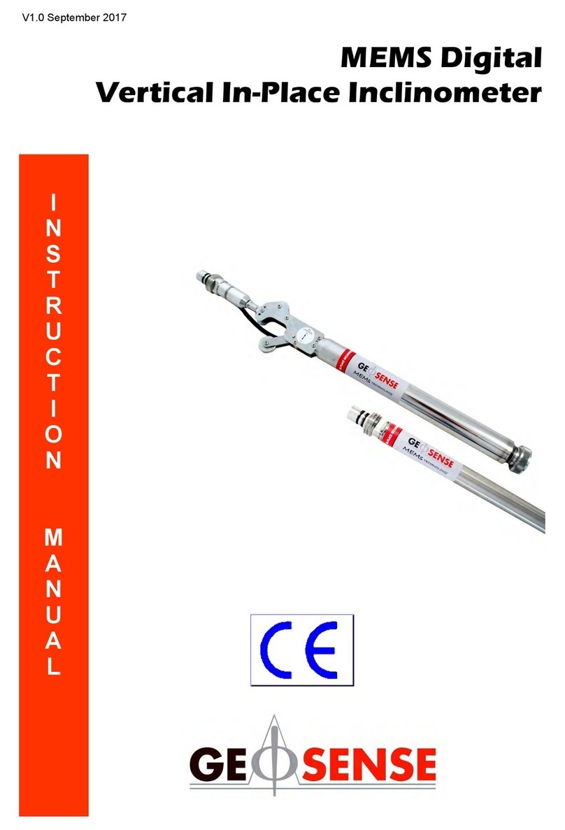
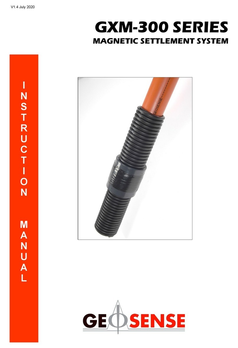
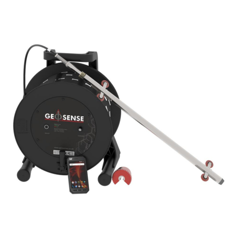
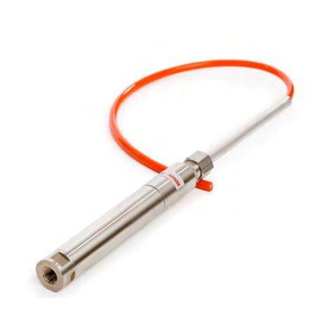
Other Geosense Measuring Instrument manuals

Geosense
Geosense MEMS DPI I User manual

Geosense
Geosense Quick Joint User manual

Geosense
Geosense GXM-300 Series User manual

Geosense
Geosense LS-G6-VW User manual

Geosense
Geosense VWPHT-3600 Series User manual

Geosense
Geosense VWCM-4000 User manual

Geosense
Geosense VWLSS-200 User manual

Geosense
Geosense IPI-V-1 User manual

Geosense
Geosense TP-1 User manual