Geosense VWPHT-3600 Series User manual

V1.0 July 2020
I
N
S
T
R
U
C
T
I
O
N
M
A
N
U
A
L
HIGH TEMPERATURE
VW PIEZOMETERS
VWPHT-3600

2
V1.0 July 2020
CONTENTS
Page
1.0 INTRODUCTION
1.1 General Description 3
1.2 Theory of operation 4
2.0 CONFORMITY 5
3.0 MARKINGS 6
4.0 DELIVERY 7
4.1 Packaging
4.2 Handling 7
4.3 Inspection 7
4.4 Storage 8
5.0 INSTALLATION 9
5.1 Zero Pressure Reading 9
5.2 Preparation for installation 11
6.0 DATA HANDLING 13
6.1 Monitoring the piezometer readings 13
6.1.1 Portable readouts 13
6.1.2 Data loggers 14
6.2 Data reduction 14
7.0 MAINTENANCE 18
8.0 TROUBLESHOOTING 18
9.0 SPECIFICATION 28
10.0 CALIBRATION 29
11.0 SPARE PARTS 30
12.0 RETURN OF GOODS 31
13.0 LIMITED WARRANTY 32

3
V1.0 July 2020
It is VITAL that personnel responsible for the
installation and use of the piezometers READ and
UNDERSTAND the manual, prior to working with the
equipment.
1.1 General Description
Geosense® VWPHT-3600 Series High Temperature Piezometers are suitable for the
extreme environments of temperature and pressure found within applications such as
geothermal heat and enhanced oil recovery systems including steam assisted gravity
drainage (SAGD) and cyclic steam stimulation (CSS).
They are capable of monitoring high temperatures up to 250°C and pressures up to 34.5
MPa. They are available in two models VWPHT-3600 for temperatures up to 200°C and
VWPHT-3610 for temperatures up to 250°C
Manufactured from high temperature and corrosion-resistant materials throughout,
together with a comprehensive temperature calibration, they provide high accuracy stable
long-term data with no zero drift.
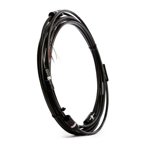
The specially-designed Tubular Encapsulated Cable (TEC) is both high temperature
resistant and highly flexible for easy installation within boreholes or above ground.
Each VW piezometer is fitted with a length of high temperature connecting cable, and an
internal high temperature thermistor.
A filter is used to protect and separate the sensing diaphragm from the surrounding
materials. It is a sintered Stainless Steel 50 micron (µm) filter, sometimes referred to as
Low (resistance to) Air Entry (LAE). The filter is mounted within a Stainless Steel housing
that is fitted onto the end of the sensor body.
Operating / calibration range
During calibration, the Geosense® range of VWPHT-3600 Series High Temperature
Piezometers / Transducers are calibrated over a series of different temperatures to
prove their function over a wide temperature range and provide the input data for any
temperature compensation that may be required.
Piezometers and Transducers are all tested to 1.5 times (150%) their standard,
calibrated, working range to prove their function at overpressure.
The calibration values will not be valid when the upper calibration value is exceeded.
However, the validity of the calibration will not be affected, providing the overpressure %
does not exceed 50 % (applied pressure is 150% working range).
1.2 Theory of Operation
(Continued on page 4)
1.0 INTRODUCTION
This manual is intended for all users of High Temperature Vibrating Wire Piezometers
VWPHT-3600 Series manufactured by Geosense® and provides information on their
principle, installation, operation and maintenance.
4
V1.0 July 2020
The Vibrating Wire Piezometer consists of a tensioned steel wire, anchored at one
end to a flexible diaphragm (the sensing element) and at the other end to the inner
body, all sealed into a stainless steel shell. The internal parts of all Geosense®
piezometers and transducers are identical. Only the thickness of the diaphragm, the
geometry of the shell and the filter arrangements change.
Two opposing coils are located within the inner body, close to the axis of the sensing
wire. When a brief voltage excitation, or swept frequency excitation is applied to the
coils, a magnetic field is generated causing the wire to oscillate at its resonant
frequency. The wire continues to oscillate for a short period through the ‘field’ of the
permanent magnets in the coils, thus generating an alternating current (sinusoidal)
output.
The frequency of the generated current output is detected and processed by a
vibrating wire readout unit, or by a data logger equipped with a vibrating wire
interface, where it can be converted into ‘Engineering’ units of pressure.
As pressure is applied to the exposed side of the flexible diaphragm (gas or liquid),
the diaphragm deflects, causing a change in the tension of the sensing wire behind it.
The change in tension of the wire results in a change in the resonant frequency at
which the wire oscillates. The change in the square of the frequency of oscillation is
directly proportional to the pressure applied.
(Continued from page 3)

5
V1.0 July 2020
2.0 CONFORMITY
Geosense Ltd
Nova House
Rougham Industrial Estate
Rougham, Bury St Edmunds
IP30 9ND
Email: [email protected].uk, Web: www.geosense.co.uk.
Declaration of Conformity
We Geosense® Ltd at above address declare under our sole responsibility that the Geosense® products
detailed below to which this declaration relates complies with protection requirements of the following
harmonized EU Directives:-
• The Electromagnetic Compatibility Directive 2014/30/EU
• Restriction on the use of certain Hazardous Substances RoHS2 2017/2102/EU
Equipment description Vibrating Wire Piezometers
Make/Brand Geosense
Model Numbers VWPHT-3600, VWPHT-3610
Compliance has been assessed with reference to the following harmonised standard:
EN 61326-1:2013 Electrical equipment for measurement, control and laboratory use.
EMC requirements. General requirements.
A technical file for this equipment is retained at the above address.
Martin Clegg
Director
July 2020

6
V1.0 July 2020
3.0 MARKINGS
Geosense® VWPHT-3600 Series High Temperature Piezometers / Transducers are labelled with the
following information:-
Product Name
Product Type
Calibrated Operating Range
Individual Serial Number
Manufacturers Name & Address
CE Mark
CABLE
The Tubular Encapsulated Cable (TEC) is supplied in a coil and can have bare conductors, a connector or
spliced onto a standard VW cable as shown below.
THE POSITION OF LABELS MAY VARY ACCORDING TO THE CABLE
REQUIREMENTS.
THE LABEL ON THE PIEZOMETER BODY SHOULD BE REMOVED PRIOR
TO INSTALLATION

7
V1.0 July 2020
4.3 Inspection / functionality check readings
It is important to check all the equipment in the shipment as soon as possible after
taking delivery and well before installation is to be carried out. Check that all the
components detailed on the documents are included in the shipment. Check that the
equipment has not been physically damaged. If any components are missing or
damaged, please contact Geosense®.
ALL Geosense® VWPHT-3600 High Temperature Piezometers carry a unique
identification serial number which is included on the label on the piezometer plus the
splice connector (where fitted) and at the free end of the cable. All VW piezometers
are supplied with individual calibration sheets that include their serial numbers and
these are shipped with the piezometers.
Cable marks also carry the model type and the length of cable fitted at the factory.
CHECK the piezometer readings against the factory ‘Zero Readings’ on arrival to
ensure they have not changed significantly due to damage during transportation.
This is a basic ‘out of the box’ functional check.
Prior to carrying out a reading check, ensure that the piezometers have been stored
in a reasonably stable temperature for at least 30 - 60 minutes.
(Continued on page 8)
4.0 DELIVERY
This section should be read by all users of VWPHT-3600 High Temperature
Piezometer Series manufactured by Geosense®
4.2 Handling
Whilst they are a robust devices, VWPHT-3600 High Temperature Piezometers are
precision measuring instruments. They, and their associated equipment, should
always be handled with care during transportation, storage and installation.
Once the shipment has been inspected (see below), it is recommended that
piezometers remain in their original packaging for storage or onward transportation.
Cable should also be handled with care. Do not allow it to be damaged by sharp
edges, rocks for example, and do not exert force on the cable as this may damage
the internal conductors and could render an installation useless.
4.1 Packaging
VWPHT-3600 High Temperature Piezometers are packed for transportation to site.
Packaging is suitably robust to allow normal handling by transportation companies.
Inappropriate handling techniques may cause damage to the packaging and the
enclosed equipment. The packaging should be carefully inspected upon delivery and
any damage MUST be reported to both the transportation company and Geosense®.

8
V1.0 July 2020
4.3 Inspection/functionality contd…
To carry out the check, connect a Vibrating Wire readout to the bare cable ends (Red
connector to Red wire and Black connector to Black wire) – The Green and White
connectors / wires are for the temperature sensor and are not required for this
checking exercise - see the readout manual for connection guidance.
Record the values (and units) displayed on the readout together with the piezometer
serial numbers.
The “CHECK” readings should coincide with the factory zero
on the calibration sheet within +/- 50 Digits (see the example
calibration sheet in Section 9) .
The elevation of the Geosense® factory is +60 metres above
sea level and barometric pressures change with altitude by
approximately 1.2kPa per 100 metres.
*however, copies may be obtained from Geosense, in
case of loss
4.4 Storage
All equipment should be stored in an environment that is protected from direct
sunlight. It is recommended that cables be stored in a dry environment to prevent
moisture migrating along inside them in the event of prolonged submersion of
exposed conductors.
Storage areas should be free from rodents as they have been known to damage
connecting cables.
No other special requirements are needed for medium or long-term storage although
temperature limits should be considered when storing or transporting associated
components, such as readout equipment.
If a piezometer is supplied with a pre-saturated filter or has been saturated on site, it
must be kept at a temperature above zero degrees Celsius. If the water freezes,
damage could be caused to the diaphragm.
(Continued from page 7)
The ‘CHECK Readings WILL be affected by temperature
changes and slightly by changes in atmospheric pressure
Calibration Sheets contain VITAL information about the
piezometer. They MUST be stored in a safe place.
Only COPIES of calibration certificates should be taken to site
The original certificates should be stored safely*.

9
V1.0 July 2020
It is VITAL that personnel responsible for the installation and
use of the piezometers READ and UNDERSTAND the manual,
prior to working with the equipment.
**********
As stated before, it is vital to check all the equipment in the shipment soon after
taking delivery and well before installation is to be carried out. Check that all
components that are detailed on the shipping documents are included.
5.0 INSTALLATION
Installation will be dependent on the actual application and therefore should be
installed in accordance with the project specification. Installation methods typically
include attachment to grout pipes or special installation rods together with other items
being installed simultaneously within the borehole.
5.1 ZERO PRESSURE Reading
Vibrating wire transducers differ from most other pressure sensors in that they
indicate a positive value at zero applied pressure. They will never read ZERO. Their
readings at ZERO PRESSURE can vary significantly between sensors.
As with most transducers, do not directly handle the Pressure Transducer when
recording the ZERO PRESSURE readings, as this will cause local temperature
gradients across the body that will distort the readings.
The Pressure Transducer is supplied with a filter inside its threaded bulkhead. The
bulkhead has a threaded socket (1/4” BSPF) that is used for connection to liquid (or
gas) pressure sources. The treaded bulkhead should be removed prior to
establishing ZERO PRESSURE values.
IT IS ESSENTIAL TO TAKE ZERO PRESSURE READINGS
BEFORE
INSTALLATION IS CARRIED OUT

10
V1.0 July 2020
The ‘on-site’ ZERO PRESSURE readings for
Vibrating Wire Piezometers and Transducers are
obtained as follows:
1. Fill a large bucket with clean, potable water,
ideally at a temperature close to 20o C. Ensure
that the bucket is away from any heat sources
in an air temperature close to 20oC. ( +/- 3oC is
acceptable). Remove any fitted filters and
place the sensor(s) in the bucket.
Leave the sensor bodies covered with water for
a minimum of 4 hours - preferably over night.
2. At the free end of the cable, connect the leads
to a vibrating wire readout unit and occasionally
monitor the sensor output by turning on the
readout and observing the display (see the
readout user manual for assistance).
Be sure to turn off the readout between periods
of readings so as to avoid ‘heating’ the Vibrating
Wire element.
3. Turn on the readout and, holding only the
5.1 ZERO PRESSURE Reading contd...
cable, lift the sensor out of the bucket, allowing it to hang vertically downwards
and immediately record 2 or 3 readings. Replace the sensor in the water as
before.
After approximately two minutes of re-immersion, repeat and record another
set of readings. Repeat three times, checking that the readings displayed are
within +/- 1 digits of each other.
4. On the calibration sheet, note these readings together with the sensor
temperature, local barometric pressure, approximate elevation above sea level,
date and time.
5. Return the sensor to the water and ensure that no air is trapped inside the
body.
6. Still all underwater, refit the filter, taking care not to trap air inside the sensor.
Either leave the sensor in the bucket of water or transfer it to another water
filled container, for transport to site for installation. If, for any reason the water
escapes from the sensor body, repeat the water filling exercise, just prior to
installation. (the Site Zero need not be repeated)

11
V1.0 July 2020
5.2 Preparation for Installation
Prior to installation of a piezometer / transducer, it is essential to establish and
confirm details of the installation to be carried out. Some of the main considerations
are listed below :-
1. Intended elevation and depth for the Sensor
This can be calculated as either the depth below a known level (ground level for
example) or as the elevation with respect to a remote datum. For borehole
installations, the final depth should be determined from the intended installation
elevation and then marked on the cable to show the intended installed position.
Which ever positioning system is adopted, it is very important to determine and
record the final elevation of the piezometer diaphragm and its orientation.
2. Borehole Installation type / specification
Where a piezometer is to be installed in a borehole, is it to be pushed into the
base of the borehole using the appropriate technique of the project
specification. In softer material, the push-in piezometer can be pushed from
ground level to its intended elevation, using hydraulic equipment such as a
Cone Penetrometer machine. This removes the need for a borehole.
3. Surface Installation type / specification
Where a piezometer is to be installed at surface level (for example: as
embankment fill is placed), is it to be pushed into a pre-formed cylindrical void
or installed in a small excavated pocket? Piezometers in these installations
would normally be covered by fill material which would be compacted manually
to a certain depth and then mechanically, thereafter.
In a location where high permeability material is present, a sand filter pocket
type installation is preferred but the sand has to be enclosed within a permeable
‘Geo-fabric’ pocket to prevent it being ‘lost’ into the surrounding materials.
Where a piezometer is to be installed in a material with a low permeability, it is
normally better pushed into a pre-formed void so as to maintain intimate contact
with the surrounding material. (Sand pockets should be avoided in low
permeability surface installations).
4. Filter zone
A specially graded sand (commonly 600 - 1200 µm) is the most common
material used to provide a filter zone within a borehole and support the borehole
around the piezometer tip. The volume of material required will depend upon
the diameter of the borehole and the length of the filter zone to be formed.
Typically a 0.5 metre long filter zone is recommended but it should be in
accordance with specific project requirements and specifications.
In some cases piezometers can be fitted inside small geotextile bags that are
then filled with filter sand. This creates a small pre-formed filter pocket but also
(Continued on page 12)

12
V1.0 July 2020
adds weight to the assembly to help with borehole installations. The filter bag
should be fitted in advance of installation, filled with sand and allowed to soak in
a bucket of water prior to placing.
5. Bentonite seal
Where a sealed piezometer filter zone is to be formed in a borehole, highly
compressed and dehydrated Bentonite in the form of either pellets, balls or
chips is commonly used to form the seal and is commercially available in
bagged form. Balls can also be created on site using Bentonite powder and
manual labour, However, small man-made bentonite balls are only suitable for
shallow boreholes with a diameter ≥ 100mm. This is because they are more
difficult to use as they can break-up before reaching their intended elevation in
deeper boreholes.
Once in place, the Bentonite expands by absorbing water to form a highly
impermeable borehole plug. Consequently, in dry boreholes, water must be
added to allow the Bentonite to swell. Normally a plug is only required above
any filter zone but a plug may also be used below a filter zone, for example,
where the borehole extends beyond a piezometer filter base elevation.
6. Cable marking.
Cables should be marked with a unique identification system. Where multiple
cables are to be grouped together along one route, markings should be
repeated at regular intervals along the cable, so that in the event of cable
damage, there may be a chance that the identification could be exposed and
the cables re-joined. Multiple cable marks are particularly important close to the
ends of the cables. The spacing of markings can vary according to specific site
requirements. As a guide, 5m to 10m is commonly applied, but closer spacing
nearer the ends.
7. Tools.
Obtain any tools necessary to carry out the installation. The following is a brief
list of tools typically used during the installation of Vibrating Wire Piezometers.
Some variation and addition may be necessary for different types of application.
• Fibre measuring tape with a weight added to the end for borehole depth
measurement and cable length measurement.
• Wire cutters and strippers
• Vibrating Wire Readout unit for checking the piezometer function
• Cable Marking system / equipment ( eg coloured PVC Tapes )
• Grout mixing and placing equipment
• PVC tape
(Continued from page 11)

13
V1.0 July 2020
6.0 DATA HANDLING
The function of an instrument is to provide useful and reliable
data. Accurate recording and handling of the data is essential
if it is to be of any value.
6.1 Monitoring the Piezometer Readings
Geosense® Vibrating Wire Piezometers and Transducers include both pressure and
temperature sensors. Where a piezometer is installed in a zone where its
temperature is likely to fluctuate significantly, records of both pressure and
temperature data should be recorded. This data can then be used to compensate for
any temperature effects on the pressure readings.
6.1.1 Portable Readouts
Geosense® offer a range of readout and data logging options. Specific operation
manuals are supplied with each readout device.
Below is a brief, step-by-step procedure for use with
the Geosense® VWR1 portable readout.
1. Connect signal cable from the sensor to the
readout following the wiring colour code.
Conductor colours may vary depending upon
the extension cable used. Commonly these
are:
RED =VW +
BLACK =VW -
GREEN =Temp
WHITE =Temp
2. Press the ‘On/Off’ button to switch the unit on. Press it
again to acquire a reading from the connected instrument.
3. The readout displays the Vibrating Wire readings in both
‘Frequency’ (in Hz) and Linear ‘B’ Digits (in Hz2/1000).
Temperature reading in both resistance (Ohms) and
degrees C.
For more details see the readout manual.
4. Press and hold down the On/Off’ button to switch the unit off.
Whilst it is not critical that the polarity be observed for most Vibrating Wire
instruments, a better signal may be obtained if the correct polarity is adopted. Since
the temperature sensor is a Thermistor, its connection polarity is not important.
6.1.2 Data Loggers
A number of data loggers are available to automatically excite, interrogate and record
(Continued on page 14)

14
V1.0 July 2020
the reading from Vibrating Wire instruments including GeoLogger, CR & Linx Series.
6.2 Data Reduction
Overview
Readings from a Vibrating Wire Readout or Logger are in a form that is a function of
frequency, rather than in units of pressure. Commonly the units would be either
Frequency - Hz, Linear ‘Digits’ (‘B’ Units) - Hz2/1000 or Hz2/1000000 or, less
commonly, Period - Time - (Seconds x10-2 or x10-7).
Linear Digits are required for all pressure conversion calculations so to convert the
readings to units of pressure, some calculation is required.
For most Vibrating Wire sensors, unique calibration factors are detailed on individual
sensor calibration sheets. A unique calibration sheet is supplied with every
Geosense® Vibrating Wire Piezometer / Transducer.
If the readout displays ‘Frequency’ values, (e.g. 2768.5 Hz) only a simple calculation
is required to convert the readings to Linear Digits.
Linear Digits (Hz2/1000) = ( 2768.5 ) 2 / 1000
=7664.6
Certain data loggers store their Vibrating Wire data in Linear Digits but further divided
by 1000. In this case the data would have to be multiplied by a further 1000 to
maintain the standard Linear Digits (Hz2/1000) format for standard calculations.
If the readout display is in the less common, Period units (e.g. 0.03612 or 3612 -
depending upon the readout used), the first step to producing an engineering value is
to convert the reading to Linear Digits (Hz2/1000). Two examples of this calculation
can be seen on the next page. The first (1) where the readout includes a decimal
point and displays the Period in Seconds x 10–2 and the second (2) where the
readout displays the Period in Seconds x 10-7
(1) Readout ‘Period’ Display =0.03612
Linear Digits (Hz2/1000) = ( 1 / 0.03612 x 10⁻² ) 2 / 1000
=7664.8
(2) Readout ‘Period’ Display = 3612
Linear Digits (Hz2/1000) = ( 1 / 3612 x 10 –7 ) 2 / 1000
=7664.8
There are a number of ways to achieve the conversion from the recorded ‘RAW’ data
to useful engineering values. The following are included as a guide only and as a
basis for alternative approaches.
(Continued from page 13)
(Continued on page 15)

15
V1.0 July 2020
Calibration
As part of the routine calibration of the ‘High Temperature’ variant of the Vibrating
Wire transducer / piezometer, Geosense subject each unit to a full range of thermal
environments. The sensor is calibrated over its pressure range to establish a
‘Calibration Factor’ and sensor ‘Zero’ at a number of thermal stages. Full calibration
information is provided on the calibration sheet supplied with each sensor.
Both the Factor and the Zero for an individual sensor will vary slightly as the
temperature changes, meaning that to compute the pressure accurately, the Factor
and Zero must be calculated using the actual sensor temperature. The temperature
is measured using the Thermistor housed within the sensor.
Since the effects of temperature changes on the Zero are almost linear, a simple
Linear equation is used to compute the Zero at a particular sensor temperature. The
effects of temperature change on the Calibration Factor are more complex so a 3rd
order Polynomial equation is used to compute the appropriate Factor. These
equations are also provided on the calibration sheet.
Examples from the attached Calibration Sheet are given below:-
Calculated Zero Reading (Digits) = M*t + C + (20°C Site Zero - 20°C Factory Zero)
Calculated Calibration K factor = A*t3 + B*t2 + C*t + D
Where ‘t’
is the
temperature at which the readings are taken in degrees C.
Linear
Calculation
Once the Zero and Factor values have been computed for the temperature at which a
reading is taken, a simple linear calculation is used to convert the ‘raw’ sensor data to
engineering units. It can be easily carried out using a calculator and assumes that
the sensor readings are in Linear Digits ( Hz2/1000 ). Where this is not the case, the
reading should be converted to these units prior to using the equation. For most
applications the equation is carried out as follows:
Pressure (kPa) = Calculated Factor (k) for kPa x (Current Reading - Calculated Zero Reading)
…...all at a particular temperature. Where the temperature changes by more than +/-
10oC, a new Zero and Calibration Factor should be calculated.
Where the Pressure is required in an alternative format, mH2O or psi for example, a
simple conversion using standard conversion factors can be applied at the end of the
equation. (1 psi = 0.7031 mH2O for example).
(Continued from page 14)
(Continued on page 16)
Where: M = -1.84474 C = 8407.01
ABCD
2.27232E-09 -2.00568E-06 1.98746E-04 -1.80619

16
V1.0 July 2020
An instrument calibration sheet similar to the example in the Section 9 of this manual
includes the following information:
Model This refers to the Geosense model number.
Serial Number This is a unique sensor identification number that can be found
on the cable just behind the sensor body and, for long
cables, at the end of the cable.
Works ID Unique works batch and range code
Calibration Date Date the calibration was performed
Baro Barometric Pressure at the time of calibration
Temp oCTemperature at which the sensor was calibrated
DPI SN Serial number of the Digital Pressure Indicator used in
conjunction with the pressure generator
R/O Cal Date The date on which the Readout was calibrated to a traceable
standard
Applied Pressure Pressure applied to the transducer as part of the calibration
cycle in both psi and kPa
Readings [digit] Readings from the transducer as pressure is applied and as
pressure is reduced, in steps. The average is calculated.
Calculated Pressure Calculation of the applied pressure using the calculated Linear
and Polynomial for comparison with the actual Applied
Pressure.
Error % fso Non Linearity expressed as a percentage of the transducers
Full Scale.
Calibration Factors ‘Linear’ calibration factors are provided for ‘kPa’ and ‘psi’
over a number of thermal steps (other units can be calculated
directly from the kPa or psi values).
Zero Equation A linear equation to obtain the correct ‘Zero’ at a particular
temperature.
Constant Equation A 3rd order polynomial equation to calculate the correct
‘Constant’ at a particular temperature.
Factory Zero Zero Pressure sensor reading at 20oC
Examples of calculated values are detailed below.
The following are examples of data reduction calculations and are based upon the
sensor to which the attached example calibration sheet refers.
A. An example of the calculation from Frequency units (Hz) to pressure, in metres
of water (mH2O) is given below:-
Site Zero Reading in Hz @ 21oC= 2896
Site Zero Reading in Linear Digits = 8386.8 (calculated from above)
Sensor Temperature = 195oC (from readout)
Calculated Zero @ 195oC= -1.84474*195 + 8407.0 + (8386.8 -
(equation from Cal Sheet) 8359.0)
= 8052.1
(Continued from page 15)
(Continued on page 17)

17
V1.0 July 2020
Calibration Factor for kPa @ 195o= (2.27232E-09*1953) + (-2.00568E-06*
(equation from Cal Sheet) 1952) + (1.98746E-04*195) - 1.80619
= - 1.82685
Current Reading in Hz = 7657.3 Hz
Current Reading in Linear Digits = 5863.4 (calculated from Hz)
Pressure Equation
Water Pressure kPa = Calculated Factor x (Current Reading - Calculated Zero)
Water Pressure kPa = - 1.82685 x (5863.4 - 8052.1)
Water Pressure = 3998.4 kPa
Water Pressure mH2O = 3998.4 / 10.1972
= 392.1 m mH2O
Barometric Pressure Considerations
In some locations, barometric pressure varies only a little, except when there are
storms. In other locations, normal weather may bring barometric pressure changes
as large as 35 mb (0.35 mH2O) during a day, and 70 mb (0.70 mH2O) during a year.
However, as most of the High Temperature variants of the Vibrating Wire sensors are
used to detect higher pressures and in sealed systems, these effects will have no, or
insignificant, effect on their data, so can be ignored.
For example, a 40mb change in pressure is equivalent to 4 kPa (0.6psi)
Temperature Considerations
Thermal influences on Piezometer / Transducer readings and its surroundings are
complex. The Thermal effects presented on the Calibration sheet relate purely to the
‘sensor’.
7.0 MAINTENANCE
The Vibrating Wire piezometer is a maintenance free device for most applications.
This is because it is intended for sub-surface installation and would normally be
irretrievably sealed into boreholes.
However, when the piezometer is installed in a location where a flow of water moves
past it and it can be recovered, a check should be made to determine the condition of
the filter. If any crystalline chemical deposits or algae are present on or in the filter, it
(Continued from page 16)
(Continued on page 18)

18
V1.0 July 2020
could affect the performance of the filter and, therefore, the piezometer.
It may be necessary to determine the nature of any build up, so that a suitable
chemical compound can be sourced to dissolve the build up, without damaging the
stainless steel of the body, filter and diaphragm. The body and sintered filter are
made from Grade 316 stainless steel.
It would only be necessary to resort to dissolving any build-up if it either blocked the
filter or there was any sign of build up on the surface of the diaphragm.
Maintenance of wiring connections between the piezometer and any terminal panels /
or loggers should involve occasional tightening of any screw terminals to prevent
loose connections or cleaning to prevent the build up of corrosion.
8.0 TROUBLESHOOTING
It is generally accepted that when a Vibrating Wire instrument is producing a stable
reading on a suitable readout, the value will be correct. Only on very rare occasions
will this be untrue.
In almost all cases, a fluctuating reading is a sign of a faulty signal from the sensor.
The fault could be in either the sensor, the connecting cable, any switch boxes or the
readout. The best way to fault find an instrument is to isolate it from all other
instruments and connections. Where possible begin fault finding from the sensor
itself.
A fault finding flow diagram is included on the next page, to help with troubleshooting.
A diagnostic resistance check routine is also included to help identify problems with
cables.
(Continued from page 17)

19
V1.0 July 2020
Isolate the Piezometer
cable from any terminals
and connect it directly to a
Vibrating Wire readout.
Switch on the Readout !
Is the Readout
showing a value ?
Is the value
displayed stable
(+/- 1 digit )
Is the readout
producing a clear
‘RING’
Check the cable
connection
Check the cable
for damage
Inspect, re-
connect or repair
There is probably nothing wrong with
the Piezometer or its cable.
Look for problems elsewhere !
If possible, switch
on the AUDIO
function on the
Readout
Is there ‘Background
Noise’ behind the ‘ring’ ?
Fit ‘EARTH’
cables to sensor
cable drain wire
(un-sheathed) and
readout devices
Has this improved the
Reading Stability ?
Check for Electrical
Earth. Try fitting
Earth cables to
readout devices &
sensor cable drain
wire (un-sheathed)
to improve reading
stability
Is the Readout
showing a value ?
There maybe
something wrong with
the Piezometer or its
cable.
Check cables with
multi-meter.
Look for problems
elsewhere !
Is the value
displayed as
expected ?
Check that
instrument number
is correct ( could
they have been
mixed up when
connections have
been made ?)
Does the instrument
respond to changes in
water pressure / level.
Could the
Piezometer have
been grouted up,
thereby sealing
the filter .. Or
similar ?
There is probably nothing wrong with
the Piezometer or its cable. The
values are probably correct
Look for problems elsewhere !
NO
YES
YES
YES
YES
YES
YES
NO
NO
NO
NO
NO
NO
YES
YES
There is either a high level of electrical
‘noise’ nearby or there maybe damage
o the connecting cable. It is unlikely to
be a problem with the Piezometer
itself.
If possible cut the cable as close to the
piezometer as possible and re-try.
NO

20
V1.0 July 2020
8.0 TROUBLESHOOTING contd…
RESISTANCE DIAGNOSTICS
Where damage to a sensor or cable is suspected this guide illustrates the way in which
simple resistance checks can be taken to identify the possible cause of the problem.
Resistance checks can be made with most types of multi-meter which are readily
available in the market.
RESISTANCE OF THE COILS
STEP 1
Set the range to 200Ω (or Ω if using a multi-meter which has automatic ranging).
STEP 2
Connect the VW+ (red) conductor to the red lead on the multi-meter and the VW- (black)
to the black lead on the multi-meter.
The correct readings should be as follows ±10%
Pressure Transducer ~ 160Ω
Strain gauge ~ 180Ω
Load Cell / Sister Bar / Miniature Strain gauge ~ 50Ω
IF THE VALUES ARE OUT OF THESE RANGES THEN THERE IS A FAULT IN THE
CABLE OR ( Less Likely) THE COILS
This manual suits for next models
2
Table of contents
Other Geosense Measuring Instrument manuals

Geosense
Geosense WI-SOS 480 User manual

Geosense
Geosense VWLSS-200 User manual

Geosense
Geosense Quick Joint User manual

Geosense
Geosense IPI-V-1 User manual

Geosense
Geosense MEMS DPI I User manual

Geosense
Geosense TP-1 User manual

Geosense
Geosense GXM-300 Series User manual

Geosense
Geosense VWCM-4000 User manual

Geosense
Geosense LS-G6-VW User manual