GeoSIG GSR-12 User manual

GeoSIG Ltd, Ahornweg 5a , 5504 Othmarsingen, Switzerland
Phone: + 41 44 810 2150, Fax: + 41 44 810 2350
GSR-12 / 16 / 18
AS-12 / 16
GCR-12 / 16
User Manual

GeoSIG Ltd. GS_GSR_GCR_UserManual_V21.doc / 18.09.2009
Page ii GSR / GCR / AS User Manual
Document Revision
Author Dr. Talhan Biro
Checked Johannes Grob
Approved Christoph Kuendig
Version Action
17.12.97 Format revision
13.09.99 Format revision
18.07.2000 Changes of name
23.08.2000 Added “Intensity Scale” (LG)
16.02.2001 Added serial data out for GSR-18, V 02.02.xx
16.07.2001 Change of new software title
15.10.2001 Changes for UL approval (LG):
Added remark “AC powered GSR only” in sections containing fuse instructions
Changed battery type of main battery from 6.5 Ah to 7.2 Ah in section 2.1.5
Added section 2.1.7 about external DC power supply
Changed pinout in appendix B for 15 VDC input (section 9)
Added section 4.2.2 about Connection of external DC power supply
Added section 4.2.5 about Interconnection installation
12.07.2002 Changes made to AS-12/16 (JG)
18.03.2003 Changes made to chapter 4.2.1 (LG)
16.04.2003 4.2.3 Requirements for the GSR foundation added (TB)
18.06.2003 Changes made to integrate GCR into GSR manual
15.01.2004 “Intensity scale” for GSR-18
08.04.2004 Adjustments concerning the new communication programs (PC)
12.05.2004 Formula format of Signal Conditioning and Triggering corrected (TB)
10.06.2004 Preliminary formatting and template change for update (TB)
GSR-18 trigger filters described (TB)
25.01.2005 Revision of Active Charge LED (TB)
16.03.2005 Changes concerning the new GSR-12 / 16 using GS_DBMN (PC)
24.05.2005 Revision of template and text flow (TB)
02.08.2005 Additional explanation for Alarm Output (PC)
07.11.2006 Update of Interconnection referring to Appendix G (TB)
11.03.2009 Change of Address [STT]
Disclaimer
GeoSIG Ltd reserves the right to change the information contained in this document without notice. While the information contained
herein is assumed to be accurate, GeoSIG Ltd assumes no responsibility for any errors or omissions.
Copyright Notice
No part of this document may be reproduced without the prior written consent of GeoSIG Ltd. The software described in this document is
furnished under a license and may only be used or copied in accordance with the terms of such a license.
Trademark
A
ll brand and product names mentioned are trademarks or registered trademarks of their respective holders.
A
ll rights reserved.
GeoSIG Ltd
Switzerland

GS_GSR_GCR_UserManual_V21.doc / 18.09.2009 GeoSIG Ltd.
GSR / GCR / AS User Manual Page iii
Table of Contents
Applicability of This Manual ................................................................................................. v
Warnings and Safety ........................................................................................................... v
Symbols and Abbreviations ................................................................................................ vi
1. Introduction...................................................................................................................... 1
2. Incoming Inspection......................................................................................................... 1
2.1. Damage During Shipment.......................................................................................................................2
2.2. Warranty..................................................................................................................................................2
3. Description....................................................................................................................... 2
3.1. Housing ...................................................................................................................................................2
3.2. LCD .........................................................................................................................................................2
3.3. LED's.......................................................................................................................................................2
3.4. Connectors..............................................................................................................................................3
3.5. Opening the Housing ..............................................................................................................................5
3.6. Printed Circuit Boards .............................................................................................................................5
3.7. Internal Battery........................................................................................................................................5
3.8. Internal Battery Charger..........................................................................................................................5
3.9. External DC Power Supply......................................................................................................................6
3.10. Test Data Sheet ....................................................................................................................................7
3.11. Options and Accessories ......................................................................................................................7
3.12. Storage..................................................................................................................................................7
4. Installation, Configuration and Operation......................................................................... 8
4.1. Site Selection ..........................................................................................................................................8
4.1.1. Environmental Considerations.........................................................................................................8
4.1.2. Power Supply Considerations..........................................................................................................8
4.2. Installation ...............................................................................................................................................9
4.2.1. Supply Voltage Selection.................................................................................................................9
4.2.2. Connection of External DC Power Supply.......................................................................................9
4.2.3. Requirements for the Instrument Foundation..................................................................................9
4.2.4. Mounting the Instrument ..................................................................................................................9
4.2.5. Optional Interconnection................................................................................................................10
4.2.6. Terminating the Installation............................................................................................................10
4.3. First Start...............................................................................................................................................11
4.4. Configuring Parameters and Putting in Operation ................................................................................11
4.4.1. Serial Data Output .........................................................................................................................11
4.4.1.1. Sample Oriented Mode (SOM)...............................................................................................12
4.4.1.2. Packet Oriented Mode (POM) ................................................................................................13
5. Functional Description ................................................................................................... 13
5.1. Signal Conditioning ...............................................................................................................................13
5.1.1. Digital Signal Filtering ....................................................................................................................14

GeoSIG Ltd. GS_GSR_GCR_UserManual_V21.doc / 18.09.2009
Page iv GSR / GCR / AS User Manual
5.1.1.1. GSR / AS Instruments ........................................................................................................... 14
5.1.1.2. GCR Instruments ................................................................................................................... 15
5.2. Triggering ............................................................................................................................................. 15
5.2.1. Internal Triggering......................................................................................................................... 16
5.2.1.1. Threshold Trigger .................................................................................................................. 16
5.2.1.2. STA/LTA Ratio Trigger .......................................................................................................... 16
5.2.2. Time Triggering ............................................................................................................................. 17
5.2.3. Software Triggering....................................................................................................................... 17
5.2.4. External Triggering (option) .......................................................................................................... 17
5.3. Triggering Guidelines ........................................................................................................................... 17
5.3.1. Threshold Trigger.......................................................................................................................... 17
5.3.2. STA/LTA Ratio Trigger.................................................................................................................. 17
5.3.2.1. Micro Event Detection............................................................................................................ 19
5.3.2.2. Local Earthquake Detection .................................................................................................. 19
5.3.2.3. Strong Motion Detection ........................................................................................................ 19
5.4. Data Recording..................................................................................................................................... 19
5.4.1. Event Directory.............................................................................................................................. 19
5.4.2. Recording Capacity....................................................................................................................... 20
5.4.3. Intensity Scale............................................................................................................................... 20
5.5. Clock..................................................................................................................................................... 20
5.5.1. GPS Option ................................................................................................................................... 21
6. Troubleshooting and Maintenance.................................................................................21
6.1. Self Test ............................................................................................................................................... 21
6.1.1. Analog ........................................................................................................................................... 21
6.1.2. Hardware....................................................................................................................................... 22
6.1.3. Real Time Clock RTC ................................................................................................................... 23
6.1.4. Battery........................................................................................................................................... 24
6.1.5. Memory ......................................................................................................................................... 24
6.2. Maintenance ......................................................................................................................................... 25
Index ..................................................................................................................................27
Appendices:
Appendix B. GSR / GCR / AS Connectors

GS_GSR_GCR_UserManual_V21.doc / 18.09.2009 GeoSIG Ltd.
GSR / GCR / AS User Manual Page v
Applicability of This Manual
a
This manual is applicable to the Firmware versions listed below:
Firmware Version Remark
V02.02.26 and up
V02.02.17 and up Only GSM support
V02.03.05 Only GSM support
V02.04.09 Only GSM support
V08.00.02
V08.01.02
V08.02.02
V08.03.02
Warnings and Safety
a
STATIC ELECTRICITY
The Instrument and if available, its sensor unit contain CMOS devices and when
serviced, care must be taken to prevent damage due to static electricity. This is very
important to ensure long term reliability of the unit.
a
INSIDE THE INSTRUMENT (MAINTENANCE)
Under normal circumstances, there is no need to remove an
y
of the printed circuit board
covers inside the Instrument, except for battery maintenance/replacement.
In any case, only trained personnel should remove these covers since power enters
directly into the Instrument and can be dangerous. Moreover untrained access may lead
to serious damage to the Instrument, as well as may void the warranty.
Especially the Lid cover should never be removed without first contacting to GeoSIG or
your local representative.
Before removing any of the covers, always:
1. Flip the main switch to "OFF"
2. Disconnect power supply from the POWER connector
3. Disconnect the main battery
4. Make sure that the green Active Charge “AC” LED indicator is OFF
a
BATTERY LIFE
The Instrument is shipped with the batteries installed and connected, ready for use. If
you do not install it immediately, you should disconnect the main battery. Do not forget
to reconnect the battery when you install the Instrument; the red cable on "+", the black
cable on “–“ poles of the battery.
In order to prevent data loss, you should be aware of that when a memory card, memory
module, back-up battery or main battery are in use, the batteries should be replaced
before their expected life time expires. Battery minimum life times under normal
conditions are:
Main battery Fiamm-GS FG20721 or FG20651 3 years
Panasonic LCR-12V6,5P 3 years
Yuasa NP 6-12 or NP 7-12 3 years
Back-up battery Varta CR 1/2 AA SLF 5 years
The lifetime of the main battery and back-up battery life can drastically change
depending on operating conditions. Strong discharge of the main battery must be
avoided. When the Instrument is not powered up, the back-up batter
y
can provide power

GeoSIG Ltd. GS_GSR_GCR_UserManual_V21.doc / 18.09.2009
Page vi GSR / GCR / AS User Manual
to the internal clock and to the memory module for a total duration of one year. During
normal operation, power comes from the main battery and the back-up battery life is at
least 5 years.
a
In case of using removable memory cards, in order to prevent data loss:
- Never remove the memory card during operation
- Do not expose the memory card to high temperatures
- Do not expose the memory card to magnetic fields or potential static electricity
discharges
Symbols and Abbreviations
Instrument GSR-12/16/18 or GCR-12/16 or AS-12/16
GSR GSR-12/16/18
GCR GCR-12/16
AS AS-12/16
CMOS Complementary Metal Oxide Semiconductor
SRAM Static Random Access Memory
EEPROM Electrically Erasable Programmable Read-Only Memory
PC Card Personal Computer Memory Card International Association (PCMCIA)
CF Memory Card CompactFlash Memory Card
VDC DC Voltage
VAC AC Voltage
STA Short Term Average
LTA Long Term Average
PC IBM©compatible Personal Computer
SPS Samples Per Second
AC Active Charge
SOM Sample Oriented Serial Output Data Mode
POM Packet Oriented Serial Output Data Mode
SEISLOG Please see
http://www.geo.uib.no/Seismologi/software/software.html
SEISAN Please see http://www.geo.uib.no/Seismologi/software/software.html
FS The full-scale input range of the instrument
DV Digital Values
AIV Analog Input Voltages
Vpp Volts peak to peak
dBRMS Root Mean Square Decibels

GS_GSR_GCR_UserManual_V21.doc / 18.09.2009 GeoSIG Ltd.
GSR / GCR / AS User Manual Page 1
1. Introduction
a
Dear Valued GeoSIG Customer, thank you for purchasing this product.
These Instruments have been optimised to meet the requirements of the majority of customers
out of the box and may have even be delivered tailored to your needs. In any case, to be able
to get the most out of our product, please carefully study this manual, its appendices and
referenced manuals, as well as any other documents delivered with it.
This is a reliable and easy to use device, and at the same time a sophisticated product, which
requires care, attention and know-how in configuring, installing, operating and maintenance.
The GCR-12/16 and GSR-12/16/18 are 12, 16 or 18 Bit seismic data acquisition systems. The AS-
12/16 is a 12 or 16 Bit seismic switch with the same specifications as the GSR or GCR instruments
with alarm trigger output but without recording facility. All these devices will be referred to as
“Instrument” in this operation manual unless needed to be specific.
Several types of internally or externally mounted sensors can be used with the Instrument, like
seismometers, geophones, accelerometers or other sensors with single-ended or differential outputs.
The GSR and GCR store the event data in CMOS SRAM, which is power maintained by internal
and/or external batteries or in removable Memory Cards (Flash EEPROM/SRAM, CF Memory Card /
PC Card). Recorded data include the sensor data, clock/timing information and instrument
configuration information.
Frequency response depends on the low-pass filter chosen. For all except GCR the frequency
response is 40% of the sample rate, whereas the sample rates are 100, 200, and 250 SPS.
During normal operation the Instrument continuously amplifies, filters and converts sensor inputs to
12, 16 or 18 Bit digital form and passes these to a pre-event memory. GCR has a permanent
(continuous) recording facility, whereas in GSR and AS, when the specified triggering criteria have
been met, the Instrument either begins recording the data from the pre-event memory and/or issues
an alarm / alarm trigger. In case of recording, by selecting an appropriate length of the pre-event
memory, you can ensure that the entire event, including the first arrival, will be recorded.
Trigger algorithms include STA/LTA ratio triggering and level triggering. The STA/LTA ratio trigger
computes the short term and long term signal averages fifty times per second (every 0.02 seconds).
When the STA exceeds a pre-selected multiple of the LTA, the Instrument begins recording data. The
level trigger continuously compares the incoming signal to a selected threshold and triggers when its
value exceeds the threshold.
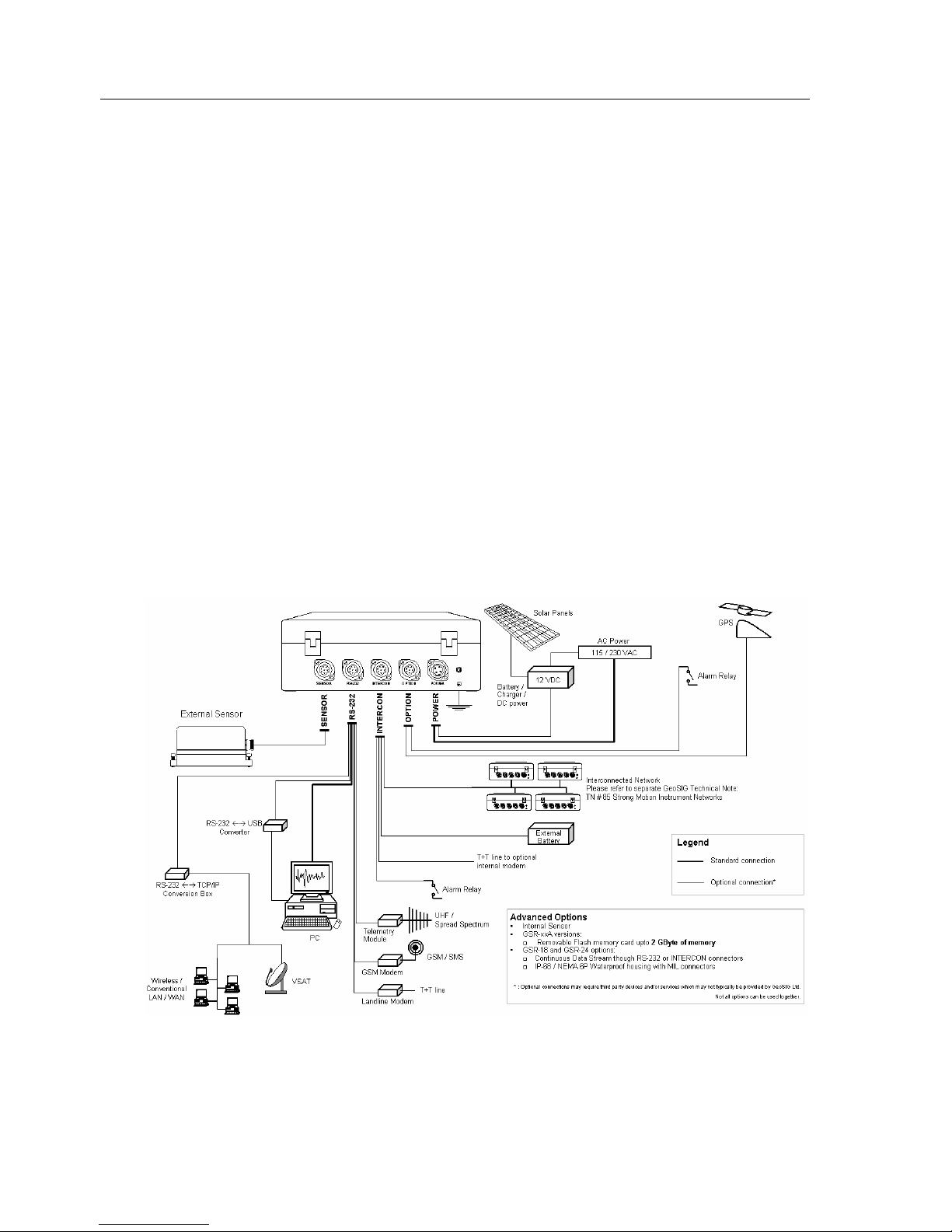
The Instrument is typically configured by connecting to a PC (both desktop and laptop models) with an
RS-232 communications port. Besides configuration, this connection facilitates data acquisition and
performing a complete system test from the sensor to the data storage memory, via the menu driven
software GeoDAS.
Configuration, data acquisition or system tests of an Instrument at a remote site may also be
accomplished through the use of modems or other telecommunication methods. Utilisation of a laptop
PC further yields the capability to perform these tasks at the site.
a
GeoSIG continuously improves and enhances capabilities of all products. There may be
several other connectivity, hardware or software options for the Instrument, which are not
covered in this manual. Refer to separate documentation from GeoSIG about available options.
2. Incoming Inspection
All Instruments are carefully inspected both electrically and mechanically before they leave the factory.
Please check if all received items correspond with the packing list and your order confirmation. In case
of discrepancy please contact GeoSIG or your local representative immediately.

GeoSIG Ltd. GS_GSR_GCR_UserManual_V21.doc / 18.09.2009
Page 2 GSR / GCR / AS User Manual
2.1. Damage During Shipment
If requested at the time of order, all instruments can be insured prior to shipment. If you receive a
damaged shipment and shipping insurance was previously arranged you should:
•Report the damage to your shipper immediately
•Inform GeoSIG or your local representative immediately
•Keep all packaging and shipping documents
a
Insurance claims may be void if the above procedure is not followed.
2.2. Warranty
GeoSIG Ltd. (hereafter GeoSIG) warrants hardware and software products against defects in
materials, workmanship and design for the defined period in the relevant contract or offer, starting
from date of shipment and 5 years parts and maintenance support commitment. If GeoSIG receives
notice of such defects during the warranty period, GeoSIG shall at its option either repair (at factory) or
replace free of charge hardware and software products that prove to be defective. If GeoSIG is
unable, within a reasonable time to repair or replace any instrument to a condition as warranted, buyer
shall be entitled to a refund of the purchase price upon return of the instrument to GeoSIG. 50 % of
freight charges on shipments of warranty repairs or replacements will be borne by GeoSIG (normally
one way freight).
Limitation of Warranty:
The foregoing guarantee shall not apply to defects resulting from:
•Improper or inadequate maintenance by buyer
•Buyer supplied software or interfacing
•Unauthorised modification or misuse
•Operation and storage outside of the environmental specifications of the instrument
or
•Improper preparation and maintenance of site.
3. Description
3.1. Housing
The Instrument is housed in a weather-resistant, IP 65, cast aluminium housing with a hinged lid.
Information regarding the Instrument's date of manufacture, serial number, etc. is contained on the ID
label on the outside of the housing.
3.2. LCD
The alphanumeric display provides detailed information about the Instrument status, incoming signal,
date and time and warning/error messages. The information to be displayed is user programmable
and can be set via GeoDAS (see the GeoDAS manual).
3.3. LED's
AC (Active Charge)
This green LED indicates that the recorder is in state of Active Charge to charge the battery. The
following 3 LED’s flash after switching on the Instrument.

GS_GSR_GCR_UserManual_V21.doc / 18.09.2009 GeoSIG Ltd.
GSR / GCR / AS User Manual Page 3
17
280mm
180mm
AC RUN EVENT ERROR
SENSOR RS-232 INTERCON OPTION POWER
Figure 1. Standard Instrument, top view
Run
This green LED flashes to indicate that the instrument is running.
Event
This yellow LED is illuminated during recording an event. After recording, the LED indicates the
presence of one or more recorded events by flashing.
Error
The red LED flashes if an error or a warning has occurred (e.g. full memory, bad sensor, low battery,
etc.).
3.4. Connectors
The Instrument has typically five connectors and a screw (when fully equipped), which are arranged in
a row on the front of the housing, as shown on Figure 2. These are labelled, from left to right:
SENSOR, RS-232, INTERCON, OPTION, POWER and (see Appendix B for connector pin-outs).
32mm68mm
Figure 2. Standard Instrument, front view
Some of these connectors are optional and may not exist on every Instrument due to customer
requirements. Some connectors support several optional hardware, which are illustrated in Figure 3.
a
Optional connections may require third party devices and/or services, which may not typically
be provided by GeoSIG.
The standard function of each connector is as follows:
SENSOR (Optional)
The SENSOR connector is a 7 or 12 pin connector, which is used to connect external sensor(s) to the

GeoSIG Ltd. GS_GSR_GCR_UserManual_V21.doc / 18.09.2009
Page 4 GSR / GCR / AS User Manual
Instrument. It carries the output signals from the sensor(s) and the test signals from the Instrument.
The SENSOR connector provides +12 VDC power to the sensor(s). Different types of sensors with
following sensor voltage output ranges are supported:
•GCR 12 / 16 recorders:
2.5 VDC ± 2.5 VDC
•AS-12 / 16 and GSR-12 / 16 / 18 recorders:
standard:
0 ± 10 VDC (20 Vpp) or 0 ± 2.5 VDC (5 Vpp) differential
optional:
0 ± 5 VDC (10 Vpp) differential
0 ± 20 VDC (40 Vpp) differential
RS-232
This connector is typically for attaching a PC to the Instrument for configuring operating parameters,
retrieving data or performing system tests. Maximum data rate is 115’200 Baud.
INTERCON (Optional)
This connector allows the Instrument to be interconnected to a recording array. Different types of
interconnections may be realised, please refer to separate documentation from GeoSIG.
OPTION (Optional)
Two options are supported by the option connector:
•The alarm option gives two different output signals (relay contacts) to activate alarm indicators
such as buzzer or flashlights.
•The connector is also used to connect an external time source such as GPS to the Instrument. The
signal of this external source can be either a pulse or an RS-232 level signal.
Figure 3. Connectivity Options
POWER
Through this four-pin connector the internal battery charger is supplied with 115/230 VAC power.
Alternatively, external batteries for powering the Instrument may be connected here (with DC Input
Option).

GS_GSR_GCR_UserManual_V21.doc / 18.09.2009 GeoSIG Ltd.
GSR / GCR / AS User Manual Page 5
(Earthing Screw) (Optional)
This is a screw to be used for proper grounding of the Instrument. When used, it has to be securely
connected to a reliable Earthing.
3.5. Opening the Housing
To open the Instrument housing, loosen all 4 screws located at the corners (Please see Figure 1).
When all 4 screws are loosened enough, the housing can be opened from its backside. This provides
access to the inside of the Instrument, which is divided into two interconnected sections, Base and Lid,
holding the Instrument components under protective covers (Please see Figure 4).
The main ON / OFF switch is placed next to the flat interconnection cable between the Base and the
Lid.
To get access to the components, remove all screws of the relevant protective cover.
a
Under normal circumstances, there is no need to remove an
y
of the printed circuit board
covers inside the Instrument, except for battery maintenance/replacement.
In any case, only trained personnel should remove these covers since power enters
directly into the Instrument and can be dangerous. Moreover untrained access may lead
to serious damage to the Instrument, as well as may void the warranty.
Especially the Lid cover should never be removed without first contacting to GeoSIG or
your local representative.
Before removing any of the covers, always:
1. Flip the main switch to "OFF"
2. Disconnect power supply from the POWER connector
3. Disconnect the main battery
4. Make sure that the green Active Charge “AC” LED indicator is off
3.6. Printed Circuit Boards
The Mainboard is mounted in the Lid under the protective cover and holds the anti-aliasing filter
circuitry, the A/D converter and the micro controller part with real time clock, memory etc. A second
circuit board may be mounted onto the main board. This option board holds the optional removable
memory card.
A separate circuit board is mounted to the front inside of the Base, which terminates the external
connectors, contains the connection for the internal sensor if available and the input protection circuits.
3.7. Internal Battery
The Instrument housing contains typically one 12 VDC, 7.2 Ah rechargeable sealed lead-acid battery.
The battery pack provides approximately 2 days of autonomy under normal operating conditions.
Additional battery capacity may be added externally (for further information, please contact GeoSIG or
your local representative).
3.8. Internal Battery Charger
a
AC powered Instrument only.
The built-in battery charger will keep the internal battery pack charged to an optimum level without the
risk of overcharging. The charger has sufficient capacity to recharge depleted batteries while the
Instrument is operating. The charger is powered by 230 VAC as standard and unless ordered different
by the customer. It can be powered by 115 VAC upon request (for further information, please contact
GeoSIG or your local representative).

GeoSIG Ltd. GS_GSR_GCR_UserManual_V21.doc / 18.09.2009
Page 6 GSR / GCR / AS User Manual
130mm
260mm
Fixation Holes
Base Cover
Lid Cover
Main Switch
Figure 4. Inside of the Instrument
a
The battery charger is just a charger. It is not a battery eliminator. DO NOT operate the
unit with only the charger attached. A battery must be connected.
a
For an external battery an external charger has to be used. Select therefore a charger with
appropriate charging characteristics for the used battery.
3.9. External DC Power Supply
a
DC powered Instrument only.
In case of DC powered Instruments, an external 15 VDC power supply is connected to the POWER
connector. Please see Appendix B for detailed pinout documentation. The utilised external DC power
supply has to be capable of delivering 200 mA or more at 15 VDC. The ripple of this DC power supply
must not exceed 100 mV p-p at 200 mA.

GS_GSR_GCR_UserManual_V21.doc / 18.09.2009 GeoSIG Ltd.
GSR / GCR / AS User Manual Page 7
3.10. Test Data Sheet
A test data sheet issued with the Instrument exactly characterises input filter performance and other
parameters measured during production test. Consult GeoSIG or your local representative for this
sheet if you wish to have precise specification of a particular instrument.
3.11. Options and Accessories
The following optional equipment is available for the Instrument:
Modem
External or internal modem. This option enables remote control/operation of the Instrument via
telephone line. On request the modem can be made capable of "Calling on Event". This means, as
soon an event triggers the Instrument, the modem automatically calls a pre-set telephone number and
transmits the recorded event (optional).
GSM Modem
The GSR-18 is also available with an external GSM modem. With this modem GSR-18 can send out
parametric information of the triggering events in the form of SMS messages.
GPS
The GPS option is a satellite navigation receiver attached to the Instrument. This unit gives the exact
information about time and position of the instrument. Full details are provided with the GPS option.
Please refer to section 5.5 for more information on GPS and internal clock.
Alarm Output
This option generates two alarm signals (for two threshold levels) in a way similar to that of the
recording trigger, thus allowing the personnel in charge to be informed immediately on the severity of
a strong event. The outputs are 2 relay contacts; either normally open (NO) or normally closed (NC)
(to be specified at order). The maximum voltage to be controlled by the relays is 24 VDC at a
maximum current of 100 mA.
Memory upgrade
The internal memory module can be expanded up to 2 Mbytes on GCR-12 / 16 and up to 128 Mbytes
on GSR-12 / 16 / 18. No memory is implemented in AS-12 / 16, thus no upgrade is possible.
Removable Memory Card
GSR instruments have a special “A” version. These instruments have a built-in interface for using ATA
Compact Flash Memory Cards (JEIDA/PCMCIA) up to 2 Gbytes.
DC Charger
The DC charger enables the user to charge the system off a single 12 VDC source. This is useful if it
is necessary to charge the system by a single 12 VDC external battery.
3.12. Storage
When not in use, the Instrument should be stored at normal room temperature in a dry location. This
will help to maximise the battery lifetime. If the instrument (recorder) is stored for more than a few
weeks, the Instrument should be attached to VAC power for 24 hours to top off the battery charge. In
this case you should remove all data records from the memory. Note that the real time clock continues
operation even when the main switch is in the OFF position. Therefore, unless the clock is turned off
by disconnecting the main battery cable, the Instrument will require occasional recharging. Recharging
for 24 hours every 2 months is recommended.
In the event of a battery failure, the memory and the real time clock are maintained by a lithium
battery.

GeoSIG Ltd. GS_GSR_GCR_UserManual_V21.doc / 18.09.2009
Page 8 GSR / GCR / AS User Manual
4. Installation, Configuration and Operation
This section lists the procedures involved in installation, configuration and operation the Instrument.
The procedures will be outlined as steps to be performed in the field or in house prior to deploying the
instrument in the field.
4.1. Site Selection
4.1.1. Environmental Considerations
The choice of an installation site for a seismic event recorder is similar in most respects to that of a
regular continuous recording seismic station.
Although the Instrument is housed in a solid, weatherproof case, it is certainly best if a location can be
arranged for the unit, which is free from direct sunlight, precipitation, the dangers of falling materials in
the event of a severe earthquake and the risk of tampering or vandalism if the unit is to be left
unattended.
There are also special considerations for event recorder installations. It is important to select the site
and set the trigger level to avoid unwanted data recording, such as vibration from machinery, highway
traffic, aircraft, waves, etc. It is wise to check the instrument frequently during the first several days of
operation after each set-up, to see if there are previously unsuspected sources of noise which are
triggering the instrument and using up the memory.
In addition, the user should select a site with a provision for 115 / 230 VAC power if the unit will be left
in place for a long period of time (more than 3 days). Although this is not necessary for the operation
of the device, it does preclude concerns about battery charging.
You should make note at this point of any cultural or environmental sources of noise and vibration
around the selected site, which may cause false triggers of the recording mechanism. These will have
to be considered when setting the trigger parameters.
4.1.2. Power Supply Considerations
The Instrument may be powered from a 115 / 230 VAC supply, from the internal battery, or a 12 VDC
external supply such as an automotive battery or solar panels (optional).
•If the supply in the field will be from a 115 / 230 VAC supply, you need to connect the VAC cable
from the Instrument to the power source only. The Instrument operates continuously, providing a
trickle charge to the internal battery. The VAC supply must consist of Phase, Neutral and
Protection Earth.
•If the supply will be exclusively from the Instrument’s internal battery, it is necessary to charge the
battery sufficiently beforehand. Make sure to have at least 24 hours of uninterrupted charging prior
to leaving the Instrument in the field. The configuration of the instrument, of course, may be
performed while the charger is connected to the Instrument. The Instrument has to be plugged to
115 / 230 VAC for charging the internal battery.
The best approach to the deployment of the Instrument is to use the internal battery along with the
VAC power at the remote site. In the lab, the Instrument can be checked and configured for the correct
time, trigger and other relevant settings. It may then be carried to the remote site (with the power
switch in the "OFF" position to conserve the internal battery) and then connected to the VAC power.
After switching to "ON", the Instrument runs with the pre-configured parameters. This reduces the
amount of time needed to configure in the field; an important consideration in the case of an adverse
condition.

GS_GSR_GCR_UserManual_V21.doc / 18.09.2009 GeoSIG Ltd.
GSR / GCR / AS User Manual Page 9
4.2. Installation
a
Many times the locations of seismic equipment are highly exposed to electrical disturbances
caused by lightning or by the industrial environment. Although the Instrument contains over
voltage protection, it may sometimes be necessary to use additional surge protectors for the
equipment. Contact GeoSIG or your local representative for more information.
4.2.1. Supply Voltage Selection
a
AC powered Instrument only.
The Instrument may be powered from 115 VAC up to 230 VAC, 50 or 60 Hz. The Instrument contains
a power supply with a transformer, which has to be configured properly to function with either 115
VAC or 230 VAC.
4.2.2. Connection of External DC Power Supply
a
DC powered Instrument only.
The DC powered Instrument can be powered from an external 15 VDC power supply through the 7
pole POWER connector. Please see Appendix B for pinout information. The external power supply
has to deliver a minimum of 300 mA at 15 VDC.
4.2.3. Requirements for the Instrument Foundation
Minimum surface area requirements
•with internal sensor: 50 x 50 cm
•with external sensor: 50 x 75 cm
•with external sensor and interconnection: 50 x 100 cm
Height requirements
Minimum surface area specifications indicated above are only applicable up to a height of maximum
25 cm. Foundation dimensions should be expanded in each direction proportionally by increasing
height.
Anchorage requirements
Foundation has to be very well anchored or adhered preferably to a rock or concrete base. In case of
a need for a foundation on soil, a concrete cubicle of 1 m3has to be cast in the ground to serve as a
base.
4.2.4. Mounting the Instrument
The following are the typical items needed for installation:
•Instrument
•Power Cable
•RS-232 Cable
•This Manual and its Appendix
•Set of Tools
•4 x M6 x 40 mm bolts with concrete anchors
•Laptop PC with GeoDAS installed, to check or configure the Instrument
•Any accessories or peripheral equipment for the Instrument and their manuals, such as external
sensor, GPS, external modem, etc.

GeoSIG Ltd. GS_GSR_GCR_UserManual_V21.doc / 18.09.2009
Page 10 GSR / GCR / AS User Manual
a
If the Instrument has an internal sensor, a water level with minimum 2 degrees accuracy is also
needed for correct levelling. In case of using external sensor, refer to the sensor manual for
mounting.
Typically follow these steps for a successful installation:
•The Instrument can be mounted in any convenient position at the location that complies with the
basic requirements outlined in section 4upto here.
a
Please note that in case of an internal sensor, orientation of the sensor would define the
positioning of the Instrument.
a
Make sure that after installation there is enough space to easily open the Lid and access inside
the Instrument as well as easily connect / disconnect any of the connectors. Also make sure
that the visual indicators on the top of the housing, i.e. the LCD and LED’s, are visible after
installation.
•Open the Instrument housing (see section 3.5)
•Fix the Instrument with the 4 x M6 x 40 mm bolts to the concrete anchors through the fixation holes
at the corners of the housing (see Figure 4).
a
If the Instrument has an internal sensor, make sure that the Instrument, or the internal sensor is
properly levelled using the levelling mechanism supplied within the sensor or the Instrument. If
no levelling mechanism is supplied, make appropriate foundation arrangements that the
Instrument is levelled to a minimum of 2 degrees from level.
•Depending on the location it may be necessary, to earth the Instrument properly. Therefore
connect the (Earthing Screw) of the Instrument via a copper wire of minimum 1.5 mm2to a
proper earth contact.
a
It is strongly recommended to have a proper Earthing.
4.2.5. Optional Interconnection
When optional Interconnection is purchased, special hardware and software installations have to be
followed. Further details on Interconnected Recording Networks and their installation are given in the
GeoSIG technical note, “TN # 85: Strong Motion Instrumentation Networks” as well as the "Appendix
G" of this Manual. Please refer to these documents to be able to properly deploy such a network.
4.2.6. Terminating the Installation
a
Fix the remaining cables, so that they may not influence the sensor signal by knocking
or vibrating at the sensor.
a
Do not leave any unpowered device connected to the Instrument.
After verifying that the physical installation is done properly, the Instrument can now be started and put
in operation as described in the following sections.
a
Do not touch the sensors and leave the installation site as quietly as possible.

GS_GSR_GCR_UserManual_V21.doc / 18.09.2009 GeoSIG Ltd.
GSR / GCR / AS User Manual Page 11
4.3. First Start
1. Connect the power cable to the POWER connector.
2. The green AC LED indicator must turn on,
If not:
▪In case of AC powered Instrument:
Disconnect the power cable from the Instrument.
Open the Lid of the Instrument (refer to section 3.5).
Check if the internal FUSE is blown.
If so, then replace it with a 500 mA slow blow fuse.
Check if the AC power is present at the plug.
▪In case of DC powered Instrument:
Check the power supply to the Instrument and the cabling.
Check the power delivery from the power supply in accordance with section 4.2.2.
3. When the problem is solved, reconnect the power cable to the Instrument.
4. Open the Lid of the Instrument (refer to section 3.5).
5. Insert the memory card if applicable.
6. Flip the main switch to its ON position.
The green RUN LED flashes once per second during the "Turn-On Delay" time (default 15
seconds). Afterwards it changes to one pulse every two seconds. This indicates that the instrument
is running.
Do not move or vibrate the sensor during the power up cycle. The Instrument is
calculating the baseline of the incoming signals; any noise could distort these signals.
You can now configure the operation parameters, start data acquisition or leave the Instrument for
operation with the actual configuration as described in the following sections.
4.4. Configuring Parameters and Putting in Operation
For configuration and data acquisition a PC running GeoDAS has to be used.
a
For the installation and usage of GeoDAS refer to the GeoDAS Manual, which explains the use
of the software in full details.
The typical procedure to be followed is to connect the cable from the PC to the RS-232 Port of the
Instrument and follow the steps described in the GeoDAS Manual to configure or perform following
functions:
•Login to and Communication with the Instrument.
•Verifying the operation of the Instrument and its sensor via Analog Signals.
•Setting Date and Time.
•Saving and/or Loading Configuration File.
•Setting Recording parameters
•Retrieving and Managing files
4.4.1. Serial Data Output
a
Only in GSR-18 delivered with “Serial Data Output” option.
With this option enabled, the Instrument will send out serial data stream through the RS-232
connection when the user logs out. As soon as GeoDAS is used to login, the Instrument stops the
data output.
The serial data stream of the Instrument contains all three channels. Depending on the configuration
that has been set via GeoDAS, it is possible to enable or disable the serial data output and select
between two modes of operation:
•Sample Oriented Mode (SOM): After logout, every sample is sent to the communication line.

GeoSIG Ltd. GS_GSR_GCR_UserManual_V21.doc / 18.09.2009
Page 12 GSR / GCR / AS User Manual
•Packet Oriented Mode (POM): After logout, every second a one-second buffer is sent to the
communication line (GSBU – GeoSIG / Bergen University – protocol).
a
For recording and analysing on the PC, besides GeoDAS, data acquisition software SEISLOG,
and data analysing software SEISAN can also be used.
Please refer to the web site of University of Bergen:
http://www.geo.uib.no/Seismologi/software/software.html
for further and up to date information on these software.
4.4.1.1. Sample Oriented Mode (SOM)
Set-up:
•Connect the cable from the PC to the RS-232 connector on the Instrument.
•Log in to the Instrument.
•Please refer to the GeoDAS manual for further steps.
Starting the serial data mode:
After logging out, the Instrument starts automatically the serial data mode after 2 seconds.
Stopping the serial data mode:
After logging in to the Instrument, the serial data mode automatically stops and remains off for the time
being logged in.
Data format:
8 bytes are sent with each sample to the COM port:
Byte 1, sync byte: 0xyy (user programmable with
the communication program)
Byte 2, data byte 1: x high
Byte 3, data byte 2: x low
Byte 4, data byte 3: y high
Byte 5, data byte 4: y low
Byte 6, data byte 5: z high
Byte 7, data byte 6: z low
Byte 8, Aux. byte: Parity check of the above data bytes
Data format is signed binary (2s complement, 16 most significant bits).
Parity check byte is defined as in Table 1.
Table 1. Definition of the parity check byte
0b 00xx xxxx
¦¦ ¦¦¦¦
¦¦ ¦¦¦+--- Bit is set, if data byte 1 has odd parity
¦¦ ¦¦+---- Bit is set, if data byte 2 has odd parity
¦¦ ¦+----- Bit is set, if data byte 3 has odd parity
¦¦ +------ Bit is set, if data byte 4 has odd parity
¦+-------- Bit is set, if data byte 5 has odd parity
+--------- Bit is set, if data byte 6 has odd parity
Baud Rate:
The transmission baud rate depends on the settings made via GeoDAS (refer to the GeoDAS manual
for further explanation). Available rates are listed on Table 2.

GS_GSR_GCR_UserManual_V21.doc / 18.09.2009 GeoSIG Ltd.
GSR / GCR / AS User Manual Page 13
Table 2. Possible baud rates with serial data stream Communication speed
1200 Baud
2400 Baud
4800 Baud
9600 Baud
19200 Baud
38400 Baud
115200 Baud
POM, 3 channels
100 SPS X X
200 SPS X
250 SPS X
SOM, 3 channels
100 SPS X X X X
200 SPS X X X
250 SPS X X
4.4.1.2. Packet Oriented Mode (POM)
Set-up:
•Connect the cable from the PC to the RS-232 connector on the Instrument.
•Log in to the Instrument.
•Please refer to the GeoDAS manual for further steps.
Starting the serial data mode:
After logging out of the Instrument, it starts automatically the serial data mode after 2 seconds.
Stopping the serial data mode:
After logging in to the Instrument, the serial data mode automatically stops and remains off for the time
being logged in.
Data format:
Standard GSBU protocol is used.
The Instrument can be directly connected to GeoDAS or SEISLOG in the “Packet” mode, which
increases the performance regarding event memory, event detection and online (GeoDAS, SEISLOG)
and offline (SEISAN) analysis enormously.
If SEISLOG is used please go through the SEISLOG manual to look up the settings required for the
Instrument.
5. Functional Description
This section discusses some of the technical details of how the Instrument works. Input signal filtering
and digitising, triggering, time accounting, data storage and event logging are among the function
described.
5.1. Signal Conditioning
Electrical signals from seismic sensors connected to the Instrument are range-adjusted in preparation
for conversion to digital form and are filtered to prevent aliasing effects. The signals are next sampled
and digitised, and then digitally filtered under software control to further reduce noise. Then these data
are used for triggering and recording.
The Instrument accepts signals from sensors within the sensor voltage output ranges as follows:
•GCR 12 / 16 recorders:
2.5V ± 2.5 VDC

GeoSIG Ltd. GS_GSR_GCR_UserManual_V21.doc / 18.09.2009
Page 14 GSR / GCR / AS User Manual
•AS-12 / 16 and GSR-12 / 16 /18 recorders:
standard:
0 ± 10 VDC (20 Vpp) or 0 ± 2.5 VDC (5 Vpp) differential
optional:
0 ± 5 VDC (10 Vpp) differential
0 ± 20 VDC (40 Vpp) differential
The Digital Values (DV) for Analog Input Voltages (AIV) are summarised in the following tables:
Table 3. DV and AIV for GCR Instruments
GCR Instruments Digital Value DV
[Bit]
Analog Input Voltage AIV
[V] GCR-12 GCR-16
Minimum input 0.0 0 0
Zero input 2.5 2’048 32’768
Maximum input 5.0 4’095 65’535
Table 4. DV and AIV for GSR and AS Instruments
GSR and AS Instruments Digital Value DV
[Bit]
Analog Input Voltage AIV
[V] GSR-12
AS-12 GSR-16
AS-16 GSR-18
Minimum input –FS –2‘048 –32‘768 –131‘072
Zero input 0.0 0 0 0
Maximum input +FS +2’047 +32’767 +131’071
FS is the full-scale input range of the instrument and takes the following values depending on the input
configuration:
Table 5. Full Scale Input Range of the Instrument
Differential input FS [V]
0 ± 2.5 V (5 Vpp) 2.5
0 ± 5 V (10 Vpp) 5.0
0 ± 10 V (20 Vpp) 10
0 ± 20 V (40 Vpp) 20
In GCR Instruments each signal channel has a low-pass 100 Hz 6th-order Butterworth analog
filter. The sensor input signal passes through this filter prior to being sampled and converted to
digital form. This filter removes signal energy at frequencies above one-half the input sampling
rate (1000 Hz) so that these higher frequencies are not aliased by the sampling process,
appearing as erroneous digitised data. The signal level above 400 Hz at the output of the
analog filter is at least 72 dB below the input level.
5.1.1. Digital Signal Filtering
5.1.1.1. GSR / AS Instruments
The anti-aliasing low-pass filter is automatically applied by the sigma-delta A/D converter based on the
selected data output rate. For 200 SPS the filter cut-off frequency is 50 Hz and for 100 SPS it is 25 Hz.
The transfer function with the linear phase response (FIR) has a (sin(x) / x)3form that provides greater
than 100 dB rejection at the notch frequencies. The relationship between the programmed cut-off
frequency and the first notch is constant (fNOTCH = 3.81 x fCUTOFF). The first notch frequency is also the
output sample rate.
Knowing exactly what happens to the data during the recording process facilitates a compensation
calculation and helps actually to get a more precise understanding about the site behaviour. Since the
This manual suits for next models
6
Table of contents