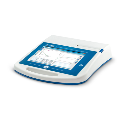
GERATHERM Ergostik User manual

Ergostik
User Manual
Version 1.2.2
Date 17th October, 2014

User Manual
Ergostik
ERGOSTIK_MAN_ENG_V1.2.2_REV01.DOCX
Page 2
1. WELCOME TO BLUE CHERRY ................................................................. 3
2. ERGOSTIK .......................................................................................... 4
2.1 DEVICE DESCRIPTION AND SCOPE OF DELIVERY .......................................... 4
2.1.1 SCOPE OF DELIVERY ............................................................................. 5
2.1.2 ACCESSORIES ..................................................................................... 6
2.1.3 SPARE PARTS...................................................................................... 8
2.2 SETUP............................................................................................... 9
2.2.1 CONNECTING THE TUBES TO THE FRONT PANEL.......................................... 9
2.2.2 FLOW SENSOR CONNECTION ............................................................... 10
2.2.3 CONNECTION ON THE REAR SIDE OF THE ERGOSTIK .................................. 11
2.2.4 CONNECT AMBISTIK .......................................................................... 12
2.2.5 SWITCH-ON ERGOSTIK ....................................................................... 12
2.2.6 SWITCH-OFF ERGOSTIK ...................................................................... 12
2.3 SECURITY......................................................................................... 13
2.3.1 GENERAL SECURITY INFORMATION ....................................................... 13
2.3.1.1 NORMS AND GUIDELINES ................................................................... 14
2.3.1.2 ELECTROMAGNETIC COMPATIBILITY ...................................................... 14
2.3.2 SECURE USE OF THE ERGOSTIK............................................................. 15
2.3.3 CLEANING AND DISINFECTING THE MASK,MOUTHPIECE AND FLOW SENSOR . 16
2.3.4 COMBINATION WITH OTHER DEVICES .................................................... 17
2.3.5 DISPOSAL ........................................................................................ 19
2.3.6 PRODUCT LABELLING ......................................................................... 19
2.3.7 USED SYMBOLS ................................................................................ 20
2.4 MAINTENANCE ................................................................................. 21
2.4.1 MAINTENANCE WORK AND -INTERVAL .................................................. 21
2.4.2 REPLACE OXYGEN CELL....................................................................... 21
2.4.3 REPLACEMENT OF NAFION ®SAMPLING LINE AND FILTER .......................... 22
3. WARRANTY ..................................................................................... 23
3.1 GENERAL DESCRIPTION ...................................................................... 23
3.2 WARRANTY EXCLUSION ...................................................................... 23
3.3 PACKING AND SHIPPING...................................................................... 23
4. TECHNICAL DATA ERGOSTIK ................................................................ 24
5. TECHNICAL DATA PULSTIK .................................................................. 25

User Manual
Ergostik
ERGOSTIK_MAN_ENG_V1.2.2_REV01.DOCX
Page 3
1. Welcome to Blue Cherry
Thank you for choosing the Blue Cherry diagnostic platform, we are sure you will be very happy
with your choice, and find the advanced functionality offered by Blue Cherry a great benefit in
your diagnostic activities.
The Blue Cherry diagnostic platform offers its user a level of functionality which is unsurpassed,
providing multiple diagnostic measurements from within a single software platform. Addition
of further diagnostic measurements couldn’t be easier: simply purchase the required hardware
and plug it into a spare USB 2.0 port on the PC. The Blue Cherry system will recognise the new
device and testing will become available within the diagnostic platform.
The Blue Cherry platform works well as a standalone device for the smallest of requirements,
however expansion for the future is simple. The software has been designed to allow
connection of multiple units to a single Blue Cherry Database to allow centralisation of data, for
the purposes of reporting or statistical analysis, further with the ability to interconnect with
many Hospital information systems using the HL7 format, the diagnostic system can be
integrated into even the largest of requirements.
This document contains important information for the operation of Blue Cherry and Ergostik.
We strongly recommend reading this manual carefully in order to avoid incorrect use or
damage to the device. Geratherm Respiratory does not take responsibility for any direct or
indirect damage to the Device, if it is not operated in accordance with this manual. Users must
observe precautions, warnings and instructions.
Geratherm Respiratory does not take liability for mistakes in this documentation. The liability
for direct or indirect losses related to the use of this document is excluded, as long as this is
allowed by law.
The copyright for Blue Cherry is owned by Geratherm Respiratory. Permission is given to use
the Blue Cherry software provided on the installation CD upon acceptance of the EULA. (see
appendix) Blue Cherry™ and Spirostik™ remain trademarks of Geratherm Respiratory.
This user manual is according to EN 60601-1 an integral part of the product. Geratherm
Respiratory reserves the right to make changes to the contents without prior notice. All
changes made are in accordance with the guidelines for manufacturing medical devices.
Geratherm Respiratory GmbH
Sparkassenpassage 1 info@geratherm-respiratory.com
D-97688 Bad Kissingen www.geratherm-respiratory.com
Tel. +49 (0)971 7857043-0 Fax +49 (0)971 7857043-30
© Copyright 2007 Geratherm Respiratory GmbH
User Manual
Ergostik
ERGOSTIK_MAN_ENG_V1.2.2_REV01.DOCX
Page 4
2. Ergostik
2.1 Device description and scope of delivery
The Ergostik device is mainly used for CPET (Cardiopulmonary
Exercise Testing). This investigation involves submaximal and
maximal treadmill or bicycle exercise with continuous
electrocardiographic monitoring and breath by breath determination
of oxygen uptake and carbon dioxide output as well as spirometry.
This allows determination of exercise capacity, peak heart rate,
maximal oxygen consumption, anaerobic threshold, respiratory gas
exchange ratio, and ventilatory equivalent for oxygen. Maximal
oxygen consumption is the best indicator of maximal cardiac reserve
and provides important prognostic information to guide the
assessment and therapy of patients with heart failure as well as other
cardiac conditions.
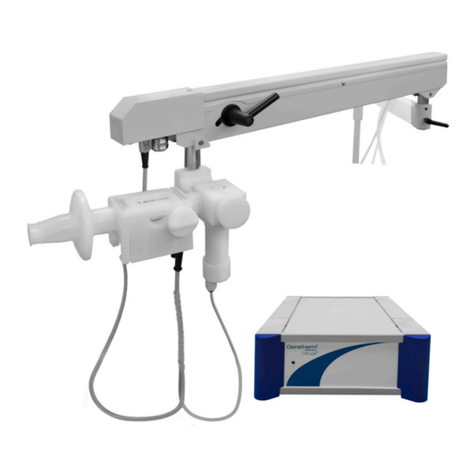
The Ergostik connects via USB to PC and consists of housing with
integrated electronics, oxygen analyser, carbon dioxide analyzer and
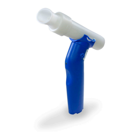
pump. For the flow measurement the proven Ergoflow flow sensor is
used.
The Ergostik runs under the powerful Blue Cherry diagnostic software
platform. The standard software is capable of measurements
including CPET and Spirometry as well as Pre/post medication
investigations and trend analysis. The software contains a powerful
database for patient and test information. Ergostik together with
Blue Cherry software has a modular design to allow the addition of
further options in the future such as MVV or Pulse Oxymetry
measurements.
The Ergostik is designed with versatility in mind, and can be used in
many areas including Sport Medicine, Pulmonary Rehabilitation, Pre-
operative assessment and Cardio Pulmonary Exercise Testing. It can
be operated in a stationary or mobile way. Ergostik is not defined to
check vital physiologic parameter. The following contraindications for
CPET testing should be taken into account: Arrhythmia, resting BP
higher than 180/100, severe respiratory insufficiency and other
severe organic diseases.

User Manual
Ergostik
ERGOSTIK_MAN_ENG_V1.2.2_REV01.DOCX
Page 5
A qualified physician should be present at all time during CPET
testing.
The modular and flexible software concept allows user specific
configuration of Blue Cherry. A User may add to the predefined
medication list, select between different predicted equations sets
and add further predicted equations, define new parameters,
configure results table and change patient data input view.
Blue Cherry can be connected to office information software via a
GDT interface. There are different export possibilities into Excel and
XML. Using the standard Microsoft ®clipboard, all charts may be
imported into standard software such as MS Word or MS
PowerPoint.
Blue Cherry has a unique report interface allowing the preview and
print of chosen numeric and Graphic data and the editing of curves
retrospectively.
2.1.1 Scope of delivery
Ergostik includes the following components:
Component
Description
Ergostik
Cardiopulmonary exercise system
Blue Cherry Software CD
Modular diagnostic platform operating under Microsoft Windows environment
Quick user guide
Flow Sensor
for measurement flow
Silicon Mouthpiece
Noseclip
Tubing set
Including flow double tube and gas sample line including filter and nafion line
Tube for gas calibration

User Manual
Ergostik
ERGOSTIK_MAN_ENG_V1.2.2_REV01.DOCX
Page 6
Component
Description
Power supply
USB cable
Silicone adapter
to connect flow sensor to calibration pump. Note user manual for indications
for the conduct of the calibration.
Ambistik including USB Dockingstation
2.1.2 Accessories
The following accessories can be purchased from you dealer:
Component
Description
Part number
Face mask Large
10.813
Face mask Medium
10.814
Face mask Small
10.810
Face mask Small
10.811
Face mask Petit
10.825
Face mask Pediatric Large
10.828
Face mask Pediatric Small
10.827

User Manual
Ergostik
ERGOSTIK_MAN_ENG_V1.2.2_REV01.DOCX
Page 7
Component
Description
Part number
Headgear M (for face mask Large,
Medium and Small)
10.812
Headgear S (for face mask Extra
Small and Petit)
10.829
Headgear (for face mask Pediatric
Small and Pediatric Large)
10.826
Maskadapter
10.815
Mouthpiece including saliva tap
10.819
Tubing set 2m
40.425
Tubing set 4m
40.425-1
Tubing set 6m
40.425-2
Pressure reducer
10.821

User Manual
Ergostik
ERGOSTIK_MAN_ENG_V1.2.2_REV01.DOCX
Page 8
2.1.3 Spare parts
The following spare parts can be purchased from your dealer:
Component
Description
Part number
Permapure tube and filter
40.424
O2 Sensor
40.401

User Manual
Ergostik
ERGOSTIK_MAN_ENG_V1.2.2_REV01.DOCX
Page 9
2.2 Setup
Before testing with the Ergostik the double pressure tube and the gas
sample tube must be connected to the front panel and also to the
Ergoflow flow sensor
Important additional information regarding the Blue Cherry
software, calibration, disinfection and testing can be found in
separate user manual. Attention should be paid to this
information.
2.2.1 Connecting the tubes to the front panel
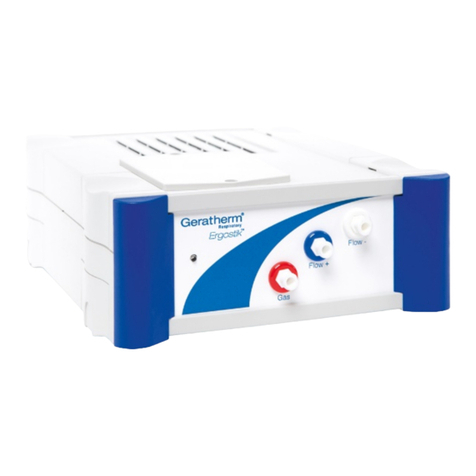
On the front side of the Ergostik device are three connectors for the
connection of the pressure tubes. These connectors are colour coded
to ensure correct connection of the tubes.
Always ensure that all tubes are connected securely. Place the
connector from the hose onto the rear connector and turn in a
clockwise direction to secure each connector,
turning counter clockwise will release each connection.
Flow- connector
Flow+ connector
Gas sample connector

User Manual
Ergostik
ERGOSTIK_MAN_ENG_V1.2.2_REV01.DOCX
Page 10
2.2.2 Flow Sensor connection
The double pressure tube and the gas sample tube should be
connected to the flow sensor as illustrated in the following
illustrations. Always ensure the tubes are firmly connected and are
not bent.
Prior to testing connect a clean disinfected mouthpiece directly to
the flow sensor.

User Manual
Ergostik
ERGOSTIK_MAN_ENG_V1.2.2_REV01.DOCX
Page 11
2.2.3 Connection on the rear side of the Ergostik
Connect the black coded end of the calibration tube to the black
connector on the rear side and the other end to the pressure reducer
of the calibration gas cylinder.
Connect the USB hook up of the Ergostik device with a spare USB
connector of the computer while using the provided USB cable.
Do not connect any tube to the yellow connector on the
rear side of the device.
The maximum allowed pressure at the calibration gas
connector is 5bar. A higher pressure can damage the
device. We recommend to only use pressure reducer
provided by Geratherm Respiratory which provide a fixed
output pressure as well as fixed output flow of 2L/min.
12V DC Power supply
Power LED
Power switch
Calibration
gas
USB connector
!! Do not use !!
Fan Canopy and FRC

User Manual
Ergostik
ERGOSTIK_MAN_ENG_V1.2.2_REV01.DOCX
Page 12
2.2.4 Connect Ambistik
Connect first the USB connector of docking station with your
computer and then Ambistik unit with the Data connector of your
docking station. The power connector must not be used.
2.2.5 Switch-on Ergostik
Connect the power supply to the rear of the Ergostik then connect
the power supply to a suitable power outlet. The device can then be
switched on using the switch at the rear side of the unit.
The Ergostik may only be operated by using the provided
power supply. See picture below.
Please ensure the power plug is easily accessible.
2.2.6 Switch-off Ergostik
The power switch on the back of the device allow to switch-off
Ergostik unit. To separate from mains voltage the power cord need to
be removed from power socket.

User Manual
Ergostik
ERGOSTIK_MAN_ENG_V1.2.2_REV01.DOCX
Page 13
2.3 Security
2.3.1 General Security information
This manual is intended for medical technical personnel, familiar with
the performance of Cardiopulmonary Exercise Testing procedures.
Geratherm Respiratory recommend that users attend a certified
training course. The instructions within this document are intended
to describe the operation of the software and the handling of the
equipment and should not be considered as training for the medical
or technical personnel.
Before using the equipment users should read and understand this
included user manual, paying attention to the operating instructions.
Geratherm Respiratory is responsible for the security and reliability
of function of the Ergostik, as such only authorized personnel should
perform changes or repairs to the system. Please consult your
Geratherm Respiratory specialist service centre for any repairs. This
equipment meets the requirements of VDE 0100
Geratherm Respiratory will not accept any warranty claims caused by
the use of alternative accessories or consumables. Always use official
Geratherm Respiratory products.

User Manual
Ergostik
ERGOSTIK_MAN_ENG_V1.2.2_REV01.DOCX
Page 14
2.3.1.1 Norms and Guidelines
The Geratherm Respiratory products are manufactured in accordance
with DIN EN ISO 13485. According to the European directive
93/42/EEC, Spirostik fulfils the requirements of annex II.
In addition the following norms are fulfilled:
- DIN EN 60601-1 (Medical electrical device)
- DIN EN 60601-1-1 (General safety requirements)
- DIN EN 60601-1-2 (EMV)
- DIN EN 60601-1-4 (Programmable electrical medical devices)
- DIN EN ISO 14971 (Risk management)
- DIN EN ISO 23747 (Peak Flow devices)
2.3.1.2 Electromagnetic compatibility
Strong radio transmitters should not be used close to the device. Do
not use mobile phones and cordless phones close to the device.
There may be an influence to medical devices. The interference
resistance is 3V/m. Do not use a higher level close to the Ergostik.

User Manual
Ergostik
ERGOSTIK_MAN_ENG_V1.2.2_REV01.DOCX
Page 15
2.3.2 Secure Use of the Ergostik
The Ergostik is a cardiopulmonary exercise system. It is highly
recommend that the user observes all warning notices in order to
ensure a safe use of the device.
The Ergostik should not be used in conjunction with multiple
connection plug sockets or extension leads
Ergostik must only be used in combination with peripheral
devices which fulfill the Norm DIN EN 60950 for office
devices or the norm DIN EN 60601 for medical electrical
devices. Always ensure the minimum requirements for the
computer are met (see technical specification). Non-Medical
devices should not be used close to a patient always ensure a
minimum distance of 1.5m between patient and non-medical
computer systems.
Flow sensors and pressure tubes must not be cleaned!
Humidity inside the pressure tube may affect the accuracy of
the measurement. Replace the pressure tube in case of
contamination. Replace the flowsensor after each patient.
Always observe instructions in the disinfection and cleaning
section.
The User must not touch the patient and the signal output of
the computer. The device should not be used in association
with a mobile power strip or extension cable.
Large quantities of saliva and/or humidity in the flow sensor
may impair the flow measurement. The flow sensor should
be replaced in these conditions. In addition extreme
temperature as well as extreme altitude may impair the flow
measurement. Consider the site conditions indicated in the
technical data.

User Manual
Ergostik
ERGOSTIK_MAN_ENG_V1.2.2_REV01.DOCX
Page 16
Disconnect the device from power supply before cleaning.
Wipe the housing and the PC using a soft cloth dampened
with a non-abrasive cleaning solution and warm water.
Remove excess fluids using a dry cloth.
For housing and PC use a surface wipe disinfection. Please
see additional notes in section disinfection.
The device should not be exposed to water or operated in
wet environments.
Ensure nothing can fall on the device; don´t put any objects
on top of the device. There are no user serviceable
components within the housing.
Never place the device on uneven or unsecured surfaces.
Should the device case become damaged the unit should be
returned for repair.
The device should not be used in dirty environments and
wherever possible in a dust free environment.
This device must not be modified without the approval of the
manufacturer
2.3.3 Cleaning and disinfecting the Mask, Mouthpiece and flow
sensor
To protect both user and subject from cross contamination risk the
mask, mouthpiece and flow sensor must be cleaned and disinfected
after use. Further information on this subject can be found in the
chapter cleaning and disinfection.
The nose clip is a single use item and must be disposed after use.

User Manual
Ergostik
ERGOSTIK_MAN_ENG_V1.2.2_REV01.DOCX
Page 17
2.3.4 Combination with other devices
Connecting additional USB devices and high processor load
can reduce the sample rate and therefore cause an error. We
strongly recommend not connecting additional USB devices
except mouse, keyboard and printer and not installing
additional software. Please contact your local dealer for
further information.
Always ensure all connections and cables are connected
properly when using the Spirostik complete together with
other devices. All connected devices must comply with legal
regulations and the total leakage current must not exceed
the maximum allowed valued specified in the Norm DIN EN
60601-1.
For some non-medical devices a higher case leakage current
is allowed. Those higher limits can only be accepted outside
patient area. It is essential to reduce the case leakage
current, if such devices are used within patient area.
The Following table (source: DIN EN 60601-1-1, table BBB.201)
explains the combination of medical electrical devices with non-
medical electrical devices:

User Manual
Ergostik
ERGOSTIK_MAN_ENG_V1.2.2_REV01.DOCX
Page 18
Situation
Medical used room
Non-medical
used room
Possible
solution
Within patient
area
Out of
patient area
resource A and B
within patient area
resource A and B
within patient area
for B: additional
protective earth
conductor or
safety
transformer
Resource A is being
power sourced by
power source of
resource B within
patient area
for B: additional
protective earth
conductor or
safety
transformer
Resource A within
patient area and
resource B in
medical used room
Resource A within
patient area and
resource B in
medical used room
See remarks
below table
Resource A within
patient area and
resource B in a non-
medical used room
See remarks
below table
Resource A within
patient area and
resource B in a non-
medical used room
for B: additional
protective earth
conductor or
separator
A
IEC 60601
B
IEC 60601
A
IEC 60601
B
IEC XXXXX
B IEC XXXXX
A
IEC 60601
A
IEC 60601
B
IEC 60601
A
IEC 60601
B
IEC XXXXX
A
IEC 60601
B
IEC 60601
or
IEC XXXXX
Combined protective earth conductor
A
IEC 60601
B
IEC 60601
or
IEC XXXXX
Protective earth conductor
Protective earth
conductor with
electrode voltage

User Manual
Ergostik
ERGOSTIK_MAN_ENG_V1.2.2_REV01.DOCX
Page 19
2.3.5 Disposal
Ergostik contains electronic components, which must
not be disposed of with domestic waste. Always ensure
disposal is carried out in accordance with local
directives.
2.3.6 Product Labelling
Example of typical product labelling:
SN: designates the serial number for the device.
The first 2 digits define the manufacturing year. The example 13
shows the device was manufactured in 2013.
The identifier |8|201| is a product specific code. The remaining digits
define the device number of the Ergostik. In this example number 1.
REF: designates the part number for the Ergostik 40 400.

User Manual
Ergostik
ERGOSTIK_MAN_ENG_V1.2.2_REV01.DOCX
Page 20
2.3.7 Used Symbols
The following table indicates all symbols used either on the product
or within this manual.
Symbol
Explanation
Pay attention to the user manual
Intended to be used only in house (dry environment)
Application component type BF according to DIN EN 60601-1
Indicates single use device
protection type II according to MDD
Separate collection of electro and electronic devices
IPX0
Indicates no protection against dripping water
Manufactured according RoHS directive 2002/95/EC
0494
Geratherm Respiratory devices carry this CE no according to directive
93/42 ECC for medical devices and fulfil the requirements of annex II
of the directive
Other manuals for Ergostik
1
Table of contents
Other GERATHERM Medical Equipment manuals

GERATHERM
GERATHERM Bodystik User manual

GERATHERM
GERATHERM Spirostik User manual

GERATHERM
GERATHERM Diffustik User manual

GERATHERM
GERATHERM UniqueResc+ User manual

GERATHERM
GERATHERM Spirostik Complete User manual

GERATHERM
GERATHERM UniqueTemp User manual

GERATHERM
GERATHERM Ergostik User manual

GERATHERM
GERATHERM Ambistik User manual

GERATHERM
GERATHERM Oxy Control User manual

GERATHERM
GERATHERM Spirostik Complete User manual