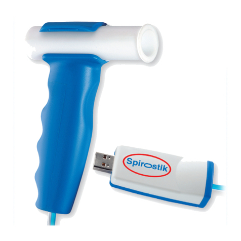
GERATHERM Spirostik User manual

Spirostik
User Manual
Version 1.2.2
Date 24th October, 2014

User Manual
Spirostik
SPIROSTIK_MAN_ENG_V1.2.2_REV01.DOCX
Page 2
1. Welcome to Blue Cherry .......................................................3
2. Spirostik.................................................................................4
2.1.1 Description and Scope of Delivery ........................................4
2.1.2 Description ............................................................................4
2.1.3 Scope of Delivery...................................................................5
2.2 Safety Instructions ................................................................6
2.2.1 General Safety Instructions...................................................6
2.2.1.1 Norms and Guidelines...........................................................7
2.2.1.2 Electromagnetic Compatibility..............................................7
2.2.2 Safe Use of Spirostik..............................................................8
2.2.2.1 Connecting Spirostik, double hose and handle.....................9
2.2.2.2 Replace handle....................................................................10
2.2.2.3 Connecting the Flow sensor into the handle ......................11
2.2.2.4 Removing the flow sensor from the handle .......................12
2.2.3 Combination with other devices.........................................14
2.2.4 Disposal ...............................................................................16
2.2.5 Product labelling .................................................................16
2.2.6 Used symbols ......................................................................17
2.3 Maintenance .......................................................................17
3. Warranty .............................................................................18
3.1 General Description ............................................................18
3.2 Warranty exclusion .............................................................18
3.3 Packing and shipping...........................................................18
4. Technical Data Spirostik ......................................................19

User Manual
Spirostik
SPIROSTIK_MAN_ENG_V1.2.2_REV01.DOCX
Page 3
1. Welcome to Blue Cherry
Thank you for choosing the Blue Cherry diagnostic platform, we are sure you will be very happy
with your choice, and find the advanced functionality offered by Blue Cherry a great benefit in
your diagnostic activities.
The Blue Cherry diagnostic platform offers its user a level of functionality which is unsurpassed,
providing multiple diagnostic measurements from within a single software platform. Addition
of further diagnostic measurements couldn’t be easier: simply purchase the required hardware
and plug it into a spare USB 2.0 port on the PC. The Blue Cherry system will recognise the new
device and testing will become available within the diagnostic platform.
The Blue Cherry platform works well as a standalone device for the smallest of requirements,
however expansion for the future is simple. The software has been designed to allow
connection of multiple units to a single Blue Cherry Database to allow centralisation of data, for
the purposes of reporting or statistical analysis, further with the ability to interconnect with
many Hospital information systems using the HL7 format, the diagnostic system can be
integrated into even the largest of requirements.
This document contains important information for the operation of Blue Cherry and Spirostik.
We strongly recommend reading this manual carefully in order to avoid incorrect use or
damage to the device. Geratherm Respiratory does not take responsibility for any direct or
indirect damage to the Spirostik, if it is not operated in accordance with this manual. Users
must observe precautions, warnings and instructions.
Geratherm Respiratory does not take liability for mistakes in this documentation. The liability
for direct or indirect losses related to the use of this document is excluded, as long as this is
allowed by law.
The copyright for Blue Cherry is owned by Geratherm Respiratory. Permission is given to use
the Blue Cherry software provided on the installation CD upon acceptance of the EULA. (see
appendix) Blue Cherry™ and Spirostik™ remain trademarks of Geratherm Respiratory.
This user manual is according to EN 60601-1 an integral part of the product. Geratherm
Respiratory reserves the right to make changes to the contents without prior notice. All
changes made are in accordance with the guidelines for manufacturing medical devices.
Geratherm Respiratory GmbH
Sparkassenpassage 1 info@geratherm-respiratory.com
D-97688 Bad Kissingen www.geratherm-respiratory.com
Tel. +49 (0)971 7857043-0 Fax +49 (0)971 7857043-30
© Copyright 2007 Geratherm Respiratory GmbH
User Manual
Spirostik
SPIROSTIK_MAN_ENG_V1.2.2_REV01.DOCX
Page 4
2. Spirostik
2.1.1 Description and Scope of Delivery
2.1.2 Description
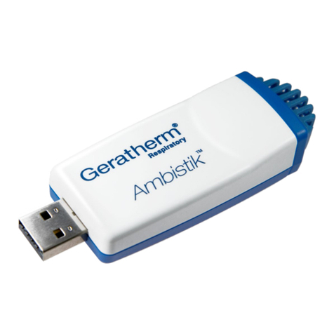
Spirostik is a PC based spirometry system. It is used in pulmonary
function testing to determine multiple parameters in spirometry.
Spirostik consists of a USB electronic module including pressure
transducers, flow sensor and a 2m double tube connecting the
pressure transducer and the flow sensor. Spirostik is supplied with
the Blue Cherry software suite.
The standard package delivered may vary according to purchase, but
may contain SVC and Flow/Volume and allow performance of
pre/post medication measurements.
The software contains a powerful database for patient and test
information. Spirostik together with Blue Cherry software has a
modular design to allow the addition of further options in the future
such as MVV or Pulse Oximetry measurements.
The main application of Spirostik is in the diagnosis of pulmonary
disease. The device is designed for use in both Primary and
Secondary care environments, and may function as a stationary
device or a mobile system in conjunction with a portable computer.
The modular and flexible software concept allows user specific
configuration of Blue Cherry. A User may add to the predefined
medication list, select between different predicted equations sets
and add further predicted equations, define new parameters,
configure results table and change patient data input view.
Blue Cherry can be connected to office information software via a
GDT interface. There are different export possibilities into Excel and
XML. Using the standard Microsoft ®clipboard, all charts may be
imported into standard software such as MS Word or MS
PowerPoint.

User Manual
Spirostik
SPIROSTIK_MAN_ENG_V1.2.2_REV01.DOCX
Page 5
Blue Cherry has a unique report interface allowing the preview and
print of chosen numeric and Graphic data and the editing of curves
retrospectively.
2.1.3 Scope of Delivery
Spirostik includes the following components:
Component
Name and Description
USB Spirostik
Electronic module connecting to USB port
Pressure tube
Connects flow sensor to pressure transducer
Single use flow sensors
Flow measurement
Grab handle
flow sensor holder
Blue Cherry software CD
Software installation CD
Quick start guide
Nose clips
Silicone adapter
to connect flow sensor to calibration syringe. Please note user manual for
instructions of the calibration.

User Manual
Spirostik
SPIROSTIK_MAN_ENG_V1.2.2_REV01.DOCX
Page 6
2.2 Safety Instructions
2.2.1 General Safety Instructions
This manual is designed to be used by technicians performing
pulmonary function testing. All users should be familiar with
pulmonary function testing and how to perform spirometry.
Geratherm Respiratory strongly recommend attendance of
certificated spirometry training course prior to use.
This manual contains instructions on how to use the software and
how to handle the device but must not be seen as a training course
for technicians or engineers.
Before using the device all users should read this manual completely
and carefully.
In terms of safety Geratherm Respiratory is only responsible, if:
- modifications or repair were done by a person authorised by
Geratherm Respiratory
- the device is used in accordance with this manual
- user observes all technical instructions
- the electrical installation where the Spirostik is used fulfil the
requirements of VDE 0100
Warranty will be void if improper accessories or consumables are
used.

User Manual
Spirostik
SPIROSTIK_MAN_ENG_V1.2.2_REV01.DOCX
Page 7
2.2.1.1 Norms and Guidelines
The Geratherm Respiratory products are manufactured in accordance
with DIN EN ISO 13485. According to the European directive
93/42/EEC, Spirostik fulfils the requirements of annex II.
In addition the following norms are fulfilled:
- DIN EN 60601-1 (Medical electrical device)
- DIN EN 60601-1-1 (General safety requirements)
- DIN EN 60601-1-2 (EMV)
- DIN EN 60601-1-4 (Programmable electrical medical devices)
- DIN EN ISO 14971 (Risk management)
- DIN EN ISO 23747 (Peak Flow devices)
2.2.1.2 Electromagnetic Compatibility
Strong radio transmitters should not be used close to the device.
Do not use mobile phones and cordless phones close to the device.
There may be an influence to medical devices.
The interference resistance is 3V/m. Do not use a higher level close
to the Spirostik.

User Manual
Spirostik
SPIROSTIK_MAN_ENG_V1.2.2_REV01.DOCX
Page 8
2.2.2 Safe Use of Spirostik
Spirostik is part of a PC based medical device. It is highly recommend
that the user observes all warning notices in order to ensure a safe
use of the device.
The Spirostik complete should not be used in conjunction with
multiple connection plug sockets or extension leads.
Spirostik must only be used in combination with peripheral
devices which fulfill the Norm DIN EN 60950 for office devices or
the norm DIN EN 60601 for medical electrical devices. Always
ensure the minimum requirements for the computer are met
(see technical specification). Non-Medical devices should not be
used close to a patient always ensure a minimum distance of
1.5m between patient and non-medical computer systems.
Flow sensors and pressure tubes must not be cleaned! Humidity
inside the pressure tube may affect the accuracy of the
measurement. Replace the pressure tube in case of
contamination. Replace the flow sensor after each patient.
Always observe instructions in the disinfection and cleaning
section.
The User must not touch the patient and the signal output of the
computer. The device should not be used in association with a
mobile power strip or extension cable.
Large quantities of saliva and/or. Humidity in the flow sensor may
impair the flow measurement. The flow sensor should be
replaced in these conditions. In addition extreme temperature as
well as extreme altitude may impair the flow measurement.
Consider the site conditions indicated in the technical data.
This device must not be modified without the approval of the
manufacturer.
Power supply can be disconnected by releasing the USB plug
connection.

User Manual
Spirostik
SPIROSTIK_MAN_ENG_V1.2.2_REV01.DOCX
Page 9
2.2.2.1 Connecting Spirostik, double hose and handle
The Spirostik is delivered with the double hose connected through
the handle to the connection points at the side of the flow sensor
grip. In order to ensure the continued function of the equipment, this
connection should be examined once per day. Please read the
following carefully:
The double hose should be securely connected to the sealing rubber
at the side of the handle, with the blue hose connected on the
patient side.
The double hose should be firmly connected with the Spirostik, with
the blue hose being connected to the connection marked dark blue.
Always ensure the double hose is not bent or damaged.

User Manual
Spirostik
SPIROSTIK_MAN_ENG_V1.2.2_REV01.DOCX
Page 10
2.2.2.2 Replace handle
Under some circumstances it may be necessary to change both the
handle and the double hose, in such case please read the following
instructions carefully. To ensure the function of the Spirostik, the
handle needs to be changed after not more than 12 months.
On the back plate of the Spirostik device there are 2 connectors
where the handle tubing can be directly connected.
Make sure to connect the blue hose (1) to the right top (blue marked
connector) and the transparent hose (2) to the left bottom
connector.
In order to secure a save use of the Spirostik device, make sure that
the tubing is connected properly as shown in the picture below:
1
2

User Manual
Spirostik
SPIROSTIK_MAN_ENG_V1.2.2_REV01.DOCX
Page 11
2.2.2.3 Connecting the Flow sensor into the handle
In order to ensure the safe function of the Spirostik, the flow sensor
must be connected correctly to the handle. Please read the following
procedure carefully.
Place the flow sensor in the ‘mouth’ of the grab handle, ensure the
flow sensor is straight and the two guidance ribs are either side of
the connector, with a firm pressure push the flow sensor into the
handle, this should ‘snap’ into place with the connector holes lined
up with the pressure double hose.
Examine that the flow sensor to ensure it is correctly engaged in the
handle: 1: Upper section of the handle must be accurately between
the two guidance ribs of the flow sensor.
2: The locating spigot must be located securely in the opening of the
guidance rib on the patient side of the flow sensor.

User Manual
Spirostik
SPIROSTIK_MAN_ENG_V1.2.2_REV01.DOCX
Page 12
2.2.2.4 Removing the flow sensor from the handle
In order to protect the user from cross contamination, the flow
sensor can be removed from the handle with a single hand without
touching the used flow sensor. Please read the following procedure
carefully:
Take the handle in the left hand and tilt the mouthpiece side of the
flow sensor downwards.
2
1

User Manual
Spirostik
SPIROSTIK_MAN_ENG_V1.2.2_REV01.DOCX
Page 13
Gently pushing the upper part of the handle with the thumb opens
the ‘mouth’ of the handle, so that the flow sensor can fall out. This
procedure can be done directly over the waste facility.

User Manual
Spirostik
SPIROSTIK_MAN_ENG_V1.2.2_REV01.DOCX
Page 14
2.2.3 Combination with other devices
Connecting additional USB devices and high processor
load can reduce the sample rate and therefore cause an
error. We strongly recommend not connecting additional
USB devices except mouse, keyboard and printer and not
installing additional software. Please contact your local
dealer for further information.
Always ensure all connections and cables are connected
properly when using the measurement device together
with other devices. All connected devices must comply
with legal regulations and the total leakage current must
not exceed the maximum allowed valued specified in the
Norm DIN EN 60601-1.
For some non-medical devices a higher case leakage
current is allowed. Those higher limits can only be
accepted outside patient area. It is essential to reduce
the case leakage current, if such devices are used within
patient area.
The following table (Source: DIN EN 60601-1-1; Table BBB.201)
explains the combination of electric medical Devices with non-
medical electric Devices:

User Manual
Spirostik
SPIROSTIK_MAN_ENG_V1.2.2_REV01.DOCX
Page 15
Situation
Medical used room
Non-medical used
room
Possible
solution
Within patient
area
Out of
patient area
resource A and B
within patient area
resource A and B
within patient area
for B:
additional
protective
earth
conductor or
safety
transformer
Resource A is being
power sourced by
power source of
resource B within
patient area
for B:
additional
protective
earth
conductor or
safety
transformer
Resource A within
patient area and
resource B in medical
used room
Resource A within
patient area and
resource B in medical
used room
See remarks
below table
Resource A within
patient area and
resource B in a non-
medical used room
See remarks
below table
Resource A within
patient area and
resource B in a non-
medical used room
for B:
additional
protective
earth
conductor or
separator
A
IEC 60601
B
IEC 60601
A
IEC 60601
B
IEC XXXXX
B
IEC XXXXX
B
A
IEC 60601
B
IEC 60601
A
IEC 60601
B
IEC XXXXX
A
IEC 60601
B
IEC 60601
or
IEC XXXXX
Combined protective earth conductor
A
IEC 60601
B
IEC 60601
or
IEC XXXXX
Protective earth conductor
Protective earth
conductor with
electrode voltage

User Manual
Spirostik
SPIROSTIK_MAN_ENG_V1.2.2_REV01.DOCX
Page 16
2.2.4 Disposal
The described Product contains electronic components,
which must not be disposed of with domestic waste. Always
ensure disposal is carried out in accordance with local
directives.
2.2.5 Product labelling
Example of a typical product labelling:
SN: designates the serial number for the device.
The first 2 digits define the manufacturing year. The example 13
shows the device was manufactured in 2013.
The identifier |8|001| is a product specific code. The remaining digits
define the device number of the Spirostik.
REF: designates the part number for the Spirostik 40 001.

User Manual
Spirostik
SPIROSTIK_MAN_ENG_V1.2.2_REV01.DOCX
Page 17
2.2.6 Used symbols
The following table indicates all symbols used either on the product
or within this manual.
Symbol
Explanation
Pay attention to the user manual
Application component type BF according to DIN EN 60601-1
Indicates single use device
protection type II according to MDD
Separate collection of electro and electronic devices
IPX0
Indicates no protection against dripping water
Manufactured according RoHS directive 2002/95/EC
0494
Geratherm Respiratory devices carry this CE no according to directive
93/42 ECC for medical devices and fulfil the requirements of annex II
of the directive
2.3 Maintenance
The Spirostik has been designed to ensure it is a low maintenance
device. Only minor maintenance is required to ensure trouble free
operation.
Interval
Maintenance work
After every patient resp. at
least once a day
Disinfection of the handle by wiping
Once a year
Replace handle

User Manual
Spirostik
SPIROSTIK_MAN_ENG_V1.2.2_REV01.DOCX
Page 18
3. Warranty
3.1 General Description
Geratherm Respiratory assures that the device fulfils the technical
data mentioned in the technical description and that this medical
device is fee from material and manufacturing defects. This limited
warranty is valid for 12 months from date of purchase. Within this
period Geratherm Respiratory will repair or replace faulty products.
The purchase date is equal to the delivery date, if purchased direct
from Geratherm Respiratory, and respectively equal to installation
date if purchased from a sales partner.
All service must be provided by Geratherm Respiratory or an
authorized service partner of Geratherm Respiratory.
Geratherm Respiratory will not accept warranty claims on any
unauthorised repairs.
3.2 Warranty exclusion
Warranty does not cover damage caused by the following:
- failure to meet the storage and transport conditions
- improper use, service or repair
- over or under voltage
- installation or use of external software
- connection with external devices
- use of the device outside the valid ambient conditions
3.3 Packing and shipping
In order to prevent damage caused by transport, devices must be
shipped in the original packing. Damage during transport caused by
improper packing will not be covered by Geratherm Respiratory.
We recommend insurance for all transport. Claims arising due to loss
or damage are not covered by Geratherm Respiratory.

User Manual
Spirostik
SPIROSTIK_MAN_ENG_V1.2.2_REV01.DOCX
Page 19
4. Technical Data Spirostik
Modifications are not permitted with this device
Technical Data:
Dimensions
Weight
76,5mm x 30mm x 18,5mm (L x W x H)
20g
Electrical Data:
IP protection type:
Protection class:
Classification according to
MDD:
Application component type:
PC interface:
Power Supply:
Power consumption:
IPX0 IEC 529
II
IIa 93/42/EWG date June 14th 1993
14.06.93 Appendix IX
BF according to VDE 0750 (DIN EN
60601-1)
USB 2.0
Via USB port
< 0,2 VA
Flow:
Flow sensor:
Measuring principle:
Measuring range:
Resistance:
Effective dead space:
Flow resolution:
Sample rate:
Accuracy:
GR Spiraflow
Differential pressure
± 16l/s
<0.09kPa/(l/s) <15l/s
< 20ml
< 1ml/s
125 Hz
±3% or 20ml/s
Volume:
Volume:
Accuracy:
0 –20L
± 3% or 50mL
Operating conditions:
Temperature:
Air humidity:
+0°C to +40°C
20 to 95% (non-condensing)
Storage and Transport
conditions:
Temperature:
Humidity:
Explosive conditions:
-10°C to +60°C
0 to 95% (non-condensing)
Device should not be used in explosive
or flammable atmospheres
Minimal requirements
PC System:
Norm:
DIN EN 60950
Processor:
Pentium III compatible or higher
1Ghz or higher recommended
500 MHz minimum
RAM Memory:
512 MB RAM or higher
192 MB RAM minimum
Hard disk:
1.5 GB or greater recommended
600 MB minimum free space required
Monitor:
XGA (1024 x 768) or higher
Interface:
USB 2.0 recomended
USB 1.1 minimum
Operating system:
Windows XP SP2 or higher
Other manuals for Spirostik
2
Table of contents
Other GERATHERM Medical Equipment manuals

GERATHERM
GERATHERM Spirostik User manual

GERATHERM
GERATHERM UniqueTemp User manual

GERATHERM
GERATHERM Oxy Control User manual

GERATHERM
GERATHERM Diffustik User manual

GERATHERM
GERATHERM Spirostik Complete User manual

GERATHERM
GERATHERM Bodystik User manual

GERATHERM
GERATHERM Bodystik User manual

GERATHERM
GERATHERM Spirostik Complete User manual

GERATHERM
GERATHERM Ergostik User manual

GERATHERM
GERATHERM Safestik User manual