GESTRA VKP 42 Ex User manual

Steam Trap Testing Equipment
VKP 42 Ex
VKP 42
Original Installation Instructions
850757-01

Contents
Foreword ............................................................................................................................................3
Availability.............................................................................................................................................3
Formatting features in the document ......................................................................................................3
Safety..................................................................................................................................................4
Use for the intended purpose .................................................................................................................4
Basic safety notes .................................................................................................................................4
Information on property damage or malfunctions.....................................................................................5
Qualification of personnel.......................................................................................................................5
Protective gear......................................................................................................................................5
Typographic features of warning notes....................................................................................................6
Formatting features for warnings of property damage ..............................................................................6
Description .........................................................................................................................................6
Scope of supply and equipment specification ..........................................................................................6
Task and function................................................................................................................................11
Storing and transporting the equipment.........................................................................................13
Storing the equipment .........................................................................................................................13
Transporting the equipment .................................................................................................................13
Operation ..........................................................................................................................................13
Preparing tests....................................................................................................................................13
Performing tests..................................................................................................................................17
Analysing tests....................................................................................................................................24
After operation .................................................................................................................................24
Switching the equipment off.................................................................................................................24
Maintaining the equipment...................................................................................................................24
Servicing the equipment and installing spare parts ................................................................................25
Troubleshooting ...............................................................................................................................25
Putting the equipment out of operation ..........................................................................................27
Removing the equipment .....................................................................................................................27
Disposing of the equipment..................................................................................................................27
Technical data..................................................................................................................................28
Dimensions and weights ......................................................................................................................28
Pressure & temperature ratings............................................................................................................28
Bluetooth ............................................................................................................................................28
Declarations of Conformity..............................................................................................................29

3
Foreword
This installation & operating manual will help you
use the steam trap test equipment safely and
efficiently for its intended purpose.
VKP 42 Ex
VKP 42
This test equipment for steam traps will be called
equipment in this document.
This installation & operating manual is intended for
anyone commissioning, using, operating, servicing,
cleaning or disposing of this equipment and, in
particular, for professional after-sales service
technicians, qualified personnel and authorised and
trained staff.
All of these persons must read and understand the
content of this installation & operating manual.
Following the instructions given in this installation &
operating manual helps avoiding danger and
increases the reliability and service life of the
equipment. Please note that in addition to the
instructions given in this installation & operating
manual you must also observe all locally applicable
rules and regulations concerning the prevention of
accidents as well as approved safety guidelines for
good professional practice.
Please also read and follow the instructions in the
manufacturers' installation & operating manual for
the data collector, especially the safety notes.
Availability
Always keep this Installation & Operating Manual in
the transport case for the equipment. Make sure
that the Installation & Operating Manual is available
to the operator.
The Installation & Operating Manual is part of the
equipment package. Hand over this Installation &
Operating Manual if you sell or pass on the
equipment to a third party.
Formatting features in the
document
Certain text elements of this installation & operating
manual feature a specific typographic design. You
can easily distinguish the following text elements:
Standard text
Cross-reference
Listing
Sub-items in listings
Steps for action.
Here you will find additional useful
information and tips serving to a
ssist you
in using the equipment to its fullest
potential.

4
Safety
Use for the intended purpose
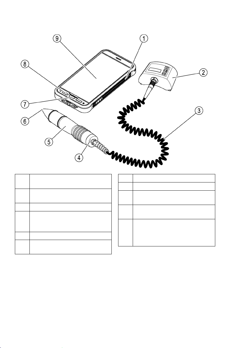
The VKP 42 steam trap testing equipment is used
for testing steam traps for loss of steam and
banking up of condensate. Do not use or operate
the VKP 42 steam trap testing equipment in
potentially explosive atmospheres.
The VKP 42 Ex steam trap testing equipment is
used in areas at risk of gas explosion for testing
steam traps for loss of steam and banking up of
condensate.
Correct use includes compliance with the
instructions given in this installation & operating
manual, in particular obedience to all safety
instructions.
Use for the intended purpose also includes
compliance with the data collector installation &
operating manual, particularly the safety notes.
Any other use of the equipment is considered to be
improper.
The following use, in particular, shall be considered
as improper use:
Using equipment without Ex protection in a
potentially explosive atmosphere
Use of the equipment by untrained personnel
Basic safety notes
Explosion hazard
Use the equipment in areas at risk of gas
explosion only under the following conditions:
In areas at risk of gas explosion, only use
equipment type VKP 42 Ex with VKPS 40 Ex
measuring transducer, VKPC 40plus Ex Com
box and VKPN 42 Ex Smart-Ex 02 *** DZ1
data collector.
Make sure that all components of the
equipment are undamaged.
Never connect or disconnect components of
the equipment in potentially explosive
atmospheres.
Never open components of the equipment in
potentially explosive atmospheres.
Do not charge batteries of individual
components of the equipment in potentially
explosive atmospheres.
Risk of explosion if the pipeline to be tested is
carrying voltage.
Before starting the test make sure that no part
of the pipeline is carrying voltage. You can
achieve this e.g. by earthing the pipeline.
There is a risk of explosion if the wrong USB
charging cable is used. Charging with the wrong
USB charging cable can damage equipment
components or batteries. If this happens,
explosion protection is no longer effective.
Only charge the VKPC 40plus Ex Com box
outside the potentially explosive atmosphere
using the supplied VKPA 40plus USB charging
cable.
Risk of explosion due to spark-over.
Do not use any items in the explosion-risk area
that could generate sparks. Do not use the
supplied file!
Pay attention to the safety notes for the
VKPN 42 Ex data collector type Smart-Ex 02 ***
DZ1. You will find these in the equipment
certificate provided.
Risk of severe injuries
Risk of deadly electric shocks if a test is
performed on live steam traps!
Make sure that the traps to be tested are not
live.
The trap to be tested is hot and under pressure.
Before carrying out any tests make sure that the
following requirements are met:
Make sure there is no skin contact with the
trap to the tested or other parts of the
installation.
Always wear protective gear when
performing the tests.
Make sure that there are no fluid leaks at the
area of the trap to be tested.
Risk of deadly electric shocks if defective
components are used!

5
Never open the components of the
equipment.
Never use any defective or damaged
components.
Before recharging the equipment make sure
that the used cables are in good working
condition.
Information on property damage
or malfunctions
Condensation may have formed in the
equipment in the event of sudden or drastic
temperature changes.
After temperature changes leave the
equipment switched off until the temperature
of the equipment reaches ambient
temperature.
Allow any condensation on the equipment to
dry out completely.
Static charges may cause damage to electronic
components and/or lead to malfunctions.
Wear electrically insulated shoes when
performing tests.
Improper handling may cause damage to
electronic components and/or lead to
malfunctions.
Never open the components of the equipment.
If the measuring probe does not touch the trap
firmly at the right position and angle the
readings may be incorrect.
Make sure the sensor tip of the measuring
probe touches only a bare metallic surface.
If the tests are performed on different points on
a steam trap the readings may be faulty.
Make sure the sensor tip touches always the
same test point. Make sure the sensor tip is
perpendicular to the surface of the steam trap
when it touches the test point.
The telephone function of the data collector can
be impaired. Observe regulations governing
wireless technology at the place of use.
Qualification of personnel
A qualified person must be acquainted with and
experienced in the following:
The pertinent on-site rules and regulations for
preventing fire and explosions as well as
industrial safety regulations
Working on pressure equipment
Working with dangerous (hot or pressurized)
fluids
Observing all notes and instructions in this
installation & operating manual and the
applicable documents
Working with portable instruments
Working with personal computers (PCs)
Working with menu-driven software
Analysing and interpreting steam trap test
results
Protective gear
The required protective gear depends on the types
of fluid used and the regulations on site. For more
information on suitable protective clothing and
safety gear refer to the safety data sheet of the fluid
in question.
Protective gear comprises the following items:
protective helmet
work boots
protective gloves
Depending on local rules and regulations and the
noise level generated by the plant some form of ear
protection must be worn.
Depending on local rules and regulations and the
fluid used in the plant some form of eye protection
must be worn.

6
Typographic features of warning
notes
DANGER
Notes with the heading DANGER warn
against imminent dangerous situations that
can lead to death or serious injuries.
WARNING
Notes with the heading WARNING warn
against possibly dangerous situations that
could lead to death or serious injuries.
CAUTION
Notes with the heading CAUTION warn
against dangerous situations that could
lead to minor or moderate injuries.
Formatting features for warnings
of property damage
Attention!
This information warns of a situation
leading to property damage.
Description
Scope of supply and equipment
specification
Scope of supply
The equipment components are supplied
individually in a transport case. Before use, you
must connect the components and charge the
batteries outside the potentially explosive
atmosphere.
Delivery includes the following items:
Transport case
Strap for securing the Com box
Data collector VKPN 42 Smart-Ex 02 *** Rugged
or VKPN 42 Ex Smart-Ex 02 *** DZ1 with
accessories (see manufacturer’s installation &
operating manual):
Charger with adapters for UK, EU, US and AU
sockets
Screwdriver
USB cable
Measuring transducer VKPS 40 Ex with
connecting cable
Com box VKPC 40plus or VKPC 40plus Ex
USB charging cable VKPA 40plus for Com box
VKPC 40plus or VKPC 40plus Ex
Power supply unit for Com box
Four power supply unit adapters for various
mains sockets
Adjustable mirror
Identification signs for valves (optional)
Analysis app TRAP
test
VKP
Do NOT use the supplied file and the adjustable
mirror in explosion-risk areas! The file and the
mirror are provided with an appropriate warning
note.
For VKP 42 Ex equipment, the following
components are intended for use in areas at risk of
gas explosion and are identified on the respective
name plates:
Data collector VKPN 42 Ex Smart-Ex 02 *** DZ1
Com box VKPC 40plus Ex
Measuring transducer VKPS 40 Ex
Accessories
Standby bag (optional, suitable for areas at risk
of gas explosion).

7
Equipment specification
VKP 42 Ex
Item
no.
Name / specification
1 On/Off key (see operating manual for the
data collector)
2
Com Box type VKPC 40plus Ex
3
Connecting cable to connect the
measuring probe with the Com Box
(firmly attached to the measuring probe)
4
Red LED (illuminated during a test)
5
Measuring transducer (=probe) type VKPS
40Ex
No.
Designation or meaning
6
Sensor tip
7 “Home” button (see data collector
installation & operating manual)
8
“Back” button (see data collector
installation & operating manual)
9
Data collector VKPN 42
Ex Smart-Ex 02 *** DZ1 (see
manufacturer’s installation & operating
manual)

8
VKP 42
Item
no.
Name / specification
1
On/Off key (see operating manual for the
data collector)
2
Com-Box type VKPC 40plus
3
Connecting cable to connect the
measuring probe with the Com Box
(firmly attached to the measuring probe)
4
Red LED (illuminated during a test)
5 Measuring transducer (=probe) type VKPS
40Ex
No.
Designation or meaning
6
Sensor tip
7
“Home” button (see data collector
installation & operating manual)
8
“Back” button (see data collector
installation & operating manual)
9
Data collector VKPN 42
Smart-Ex 02 *** Rugged (see
manufacturer’s installation & operating
manual)

9
Indicators and adjustors on the Com box
Item
no.
Description
10
ON/OFF button
11
Charge indicator
LED illuminated green: the battery of the Com Box is charged. The Com Box is not connected to
the mains power.
LED pulsing green: the Com Box is connected to the mains power and the battery is being
charged.
LED illuminated amber: the charge of the battery of the Com Box is low. Please recharge the
battery at the next opportunity.
LED illuminated red: the charge of the battery of the Com Box is too low. Recharge the battery.
If the LED is not illuminated the storage battery of the Com Box is charged. Disconnect the Com
Box from the mains power.
12
Status indicator for Bluetooth connection
LED illuminated blue: Bluetooth connection established to the data collector.
LED pulsing blue: the Bluetooth connection to the data collector is being established or data are
being transferred.
There is no Bluetooth connection to the data collector if the LED is not illuminated.

10
Name plate
Name plates are affixed to the individual
components:
Data collector:
Equipment name plate on rear
The explosion-proof equipment (VKP 42 Ex)
also has the ATEX test number on the name
plate.
Com box: Name plate on rear behind the carry
strap
USB charging cable for Com box: Inscribed on
housing
Measuring transducer: Inscribed on housing
The name plates contain the following indications:
Manufacturer
Type designation
Serial number
Admissible range of service temperature
Traceability
The VKP 42 Ex is subject to the traceability rules of
Directive 2014/34/EU.
For this reason, the name plates of the testing
equipment (complete testing equipment, data
collector, Com box and measuring transducer)
contain serial numbers.
The serial numbers can be found on the following
name plates:
Complete testing equipment: Name plate on
transport case
Data collector VKPN 42 Ex: Equipment name
plate on rear
Com box VKPC 40 Plus Ex: Name plate on rear
Measuring transducer VKPS 40 Ex: Inscribed on
housing
When purchasing the testing equipment or
individual components, the customer data is linked
to the relevant serial numbers, which ensures
traceability. If the testing equipment or individual
components are resold or passed on, the vendor is
responsible for ensuring that traceability is
maintained. To do this, the vendor must archive the
new owner’s data together with the serial numbers
of the testing equipment/components, and share
this data with GESTRA AG if so requested.
Alternatively, the vendor can also transfer this data
directly to GESTRA AG. In this case GESTRA AG, as
the manufacturer, takes on responsibility for the
relevant data.
ATEX-/IECEx Directive
VKP 42 Ex equipment is approved for use in
potentially explosive atmospheres. You can find
more detailed information on the data collector
VKPN 42 Ex Smart-Ex 02 *** DZ1 in the data
collector installation & operating manual.
The following components are approved for use in
potentially explosive atmospheres:
Data collector VKPN 42 Ex Smart-Ex 02 *** DZ1
with Ex classification
Measuring transducer VKPS 40 Ex with Ex
classification
Com box VKPC 40plus Ex with Ex classification
Standby bag (optional) with Ex classification
Do NOT use the supplied file and the adjustable
mirror in explosion-risk areas! The file and the
mirror are provided with an appropriate warning
note.
Data collector VKPN 42 Ex Smart-Ex 02 *** DZ1
has the following classification:
II 2G Ex ib op is IIC T4 Gb IP64
II 2D Ex ib op is IIIC T120°C Db
EPS 19 ATEX 1 068 X
IECEx EPS 19.0031X
For more information on the markings on the data
collector see the operating manual for the data
collector.

11
Com box VKPC 40plus Ex has the following
classification:
VKPC 40plus Ex
II 2G Ex ib IIC T4 Gb
BVS 15 ATEX E002
Ex ib IIC T4 Gb
IECEx BVS 18.0048
Only VKPS 40 Ex measuring transducers with the
classification Ex ib IIC T4 Gb may be connected to
the VKPC 40plus Ex Com box.
Components may only be connected and
disconnected outside the potentially explosive
atmosphere.
Measuring transducer VKPS 40 Ex has the following
classification:
VKPS 40Ex
Ex ib IIC T4 Gb
Additional information for use in the USA and
Canada
This device contains:
FCC ID: T9J-RN42
IC: 6514A-RN42
This device complies with Part 15 of the FCC Rules
and with Industry Canada license exempt RSS
standard(s).
Operation is subject to the following two conditions:
(1) this device may not cause harmful interference,
and
(2) this device must accept any interference
received, including interference that may cause
undesired operation.
Le présent appareil est conforme aux CNR
d'Industrie Canada applicables aux appareils radio
exempts de licence.
L'exploitation est autorisée aux deux conditions
suivantes:
(1) l'appareil ne doit pas produire de brouillage, et
(2) l'utilisateur de l'appareil doit accepter tout
brouillage radioélectrique subi, même si le
brouillage est susceptible d'en compromettre le
fonctionnement.
This equipment has been tested and found to
comply with the limits for a Class B digital device,
pursuant to part 15 of the FCC Rules. These limits
are designed to provide reasonable protection
against harmful interference in a residential
installation. This equipment generates, uses and
can radiate radio frequency energy, and if not
installed and used in accordance with the
instructions, may cause harmful interference to
radio communications.
However, there is no guarantee that interference
will not occur in a particular installation. If this
equipment does cause harmful interference to radio
or Television reception, which can be determined by
turning the equipment off and on, the user is
encouraged to try to correct the interference by one
or more of the following measures:
Reorient or relocate the receiving antenna.
Increase the separation between the equipment
and receiver.
Connect the equipment into an outlet on a
circuit different from that to which the receiver
is connected.
Consult the dealer or an experienced radio/TV
technician for help.
Task and function
Purpose
The VKP 42 testing equipment is used for testing
steam traps for loss of steam and banking up of
condensate.
The VKP 42 Ex testing equipment is used in areas
at risk of gas explosion for testing steam traps for
loss of steam and banking up of condensate.
To use the VKP 42, you will need the supplied app
to analyse the test data. Further information can be
found in the operating instructions for this app.

12
You can start the test via the test objects, or create
a test object in the data collector during the test:
Create test objects in the app and retrieve them
using the “Test jobs” button on the data
collector.
Quick check: The test object is created during
this rapid test.
During the test procedure the surface temperature
of the tested steam trap is also measured, which
makes it possible to detect waterlogged steam
traps. In order to do so you have to enter the
service pressure upstream of the test object. The
boiling point associated with this service pressure is
then compared with the temperature reading. If the
measured temperature is below 40 % of the boiling
point, the steam trap is waterlogged and banking
up condensate.
If the test results are affected by noise produced by
other components of the plant you can perform a
foreign noise measurement. This will help you to
test and evaluate the influence of foreign noise on
the test results.
Function
When fluid is flowing through steam traps, this
produces ultrasonic vibrations. When the sensor tip
is in position, these vibrations are picked up by the
measuring transducer. At the same time, the
temperature at the measuring point is measured by
a thermocouple in the measuring transducer.
The measuring transducer converts the readings
into digital signals. These signals are transferred to
the Com box by the permanently attached cable.
The Com box transfers the readings to the data
collector via Bluetooth. The readings are then
graphically displayed on the data collector and
stored there.
Synchronisation of the data collector with the
analysis app differs depending on which version of
the VKP 42 you have:
Via the supplied USB cable (only outside the
potentially explosive atmosphere)
Wirelessly via Wi-Fi
Wirelessly via mobile data
The test results are analysed on the basis of noise
limit values. These values were established through
tests by the manufacturer.
The steam trap does not lose any steam if the
following conditions are simultaneously met:
One reading is below the threshold, and
the temperature reading is above 40 % of the
set point
The steam trap also does not lose any steam if the
following conditions are simultaneously met:
The reading is above the threshold, and
the noise limit value is not reached across an
average of all readings in this test, and
the temperature reading is above 40 % of the
set point
If this is not the case, either extraneous noise has
influenced the readings or the steam trap is faulty.
To determine whether extraneous noise is
responsible, you can measure this with the testing
equipment. In this case, the data collector menu
will prompt you to do this after the test.
Steam traps with thermodynamic regulator are
assessed based on the limit frequency of
operations.
If you have not entered the working
pressure, the test merely
checks whether
the temperature is above 40
°C. In this
case, banking up of condensate is not
indicated.

13
Storing and transporting the
equipment
Use only the supplied hard case for storing the
equipment.
When not in use, charge the data collector and
Com box at least every six months (see
“Recharging the batteries” on page 13).
Storing the equipment
Please observe the following items when storing
the equipment:
Protect the equipment and all components
against hard shocks and impacts.
Store the equipment only indoors.
The requirements specified under "Technical
Data" on page 28 must be observed.
Make sure that all these requirements are
always met when storing the equipment.
Please contact the manufacturer if you cannot
comply with the recommended storage
conditions.
Transporting the equipment
Meet the requirements for storage also when
transporting the equipment.
For transport, comply with the conditions in the
technical data on page 28.
Outside potentially explosive atmospheres, only
transport the equipment in the supplied
transport case.
When transporting the equipment to the location
of use, make sure it is secured against falling
and impacts.
In potentially explosive atmospheres, only
transport the equipment connected and in the
optional standby bag with Ex classification.
When transporting the equipment observe
international regulations for the transport of
lithium-ion batteries.
Operation
Preparing tests
Recharging the batteries
DANGER
Sparks
generated when charging the
equipment can cause an explosion.
Recharge the batteries of the Com box
and the data collector only outside the
explosion-risk area.
DANGER
Risk of explosion if a wrong USB power
cable ("charger") is used!
Use only the supplied USB power
cable ("charger") for recharging the
battery of the Com Box type
VKPC 40plus Ex
If another USB power cable ("charger") is used
parts of the Com Box may be damaged. In this case
the equipment is no longer explosion proof.
The correct USB power cable ("charger") and the
connection for the USB power cable ("charger") on
the Com Box are marked with the stock code
number 393081 of the USB power cable
("charger").
Attention!
If
the equipment is used after sudden
and/or drastic temperature changes
condensation may form in the equipment.
This can lead to malfunctions or damage.
After temperature changes leave the
equipment switched off until the
temperature of the equipment reache
s
ambient temperature.
Do not recharge the equipment during
this time.

14
Attention!
If the equipment is not fully charged, data
may
be lost.
Always fully charge all components of
the equipment outside of the
potentially explosive atmosphere
before use.
Immediately charge the equipment
outside the potentially explosive
atmosphere if the charge indicator on
the data collector display is in the red
zone.
If the battery charge is too low the COM Box will
switch off automatically. If it is then switched on
again without prior recharging the battery may be
exhausted completely. The battery may be
damaged and data may be lost.
To avoid this allow the battery to charge for at
least 30 minutes before switching the COM box
on again.
Before using the equipment for the first time, you
must charge the batteries in the Com box and the
data collector outside the potentially explosive
atmosphere.
If the temperature of the battery is too high
or too low the charging process of the data
collector and the Com Box is stopped
automatically to
prevent the batteries from
overloading.
The max. temperature is 35
°C (95 °F),
the min. temperature 0
°C (32 °F).
The charging process will continue
automatically as soon as the temperature
of the battery is again within the
admissible temperature limits
.
Charge the data collector battery outside of the
potentially explosive atmosphere as described in
the data collector installation & operating
manual.
To connect the Com box to mains electricity with
different mains sockets, you can connect various
adapters to the power supply unit. Proceed as
follows to change the adapter:
Press the catch (15) on the adapter.
Disconnect the adapter (14) from the power
supply unit (13).
Push the required adapter onto the power
supply unit until it clicks into place.
Make sure that the USB connector is securely
inserted in the USB port (16).
The drawing shows the power supply unit for the
Com Box (stock code number 393226). The power
supply unit (stock code number 393080) can also
be used.
DANGER
Sparks generated when charging the
equipment can cause an expl
osion.
Recharge the batteries of the Com box
and the data collector only outside the
explosion-risk area.

15
To charge the battery of the Com Box proceed as
follows:
Unplug the connecting cable of the measuring
probe from the jack (17) in the Com Box.
Align the marking on the plug of the USB power
cable ("charger") (18) with the marking on the
jack (17).
Insert the plug into the jack until it hits a stop.
Connect the USB power cable ("charger") with
the power supply unit to the power supply.
Connecting components
Take the equipment out of the transport
packaging.
Check the equipment for transport damage.
Contact the manufacturer if you detect any kind
of shipping damage.
DANGER
Sparks generated when connecting the
equipment can cause an explosion.
Connect the Com box and the
measuring probe always outside the
explosion-risk area!
To connect the Com box with the data collector
proceed as follows:
Align the marking on the plug (18) with the
marking on the jack (17).
Insert the plug into the jack until it hits a stop.
The back of the Com box is provide
d with
belt straps. If you do not want to carry the
Com box during the test procedure you
can attach it to your belt or to the supplied
strap.

16
Switching on the equipment
Attention!
If the equipment is used after sudden
and/or drastic temperature changes
condensation may form in the equipment.
This can lead to malfunctions or damage.
After temperature changes leave the
equipment switched off until the
temperature of the equipment reaches
ambient temperature.
Do not recharge the equipment during
this time.
To switch the Com Box on press the ON/OFF
button (10).
The LEDs (11, 12) on the Com Box light up briefly.
To switch the Com Box off press the ON/OFF
button (10) and hold it down for three seconds.
The measuring probe is switched on as soon as it is
connected to the Com Box and the Com Box is
switched on.
To switch on the data collector press the On/Off
button.
Setting up the data collector
Before starting a test, you must enter the following
basic settings:
Set the menu language
Enable Bluetooth
To do this, proceed as described in the data
collector Installation & Operating Manual.
Using the VKP 42 app
To start the VKP 42 app, tap the relevant icon
on the display of the data collector.
The main menu is displayed.
The name of the program is shown in the title bar.
To the right of this is a button for opening
submenus.
Tap the button to open submenus.
To see information about the manufacturer of
the program, tap “Imprint”.
To see information on the licence agreement,
tap “EULA”.
To see a list of abbreviations used, tap
“Abbreviations”.
To pair the data collector with a Com box via
Bluetooth, tap “Bluetooth”.
For more information on pairing, see page 17.
The status of the data collector’s Bluetooth
connection is shown below the title bar. Next to
this, you will see the battery charge indicator. The
charge status of the Com box (“VKPC”) is only
displayed if you have paired the Com box with the
data collector.
Below this you will find buttons for using the
program. The “Data Transfer” button is only
enabled if the data collector is connected to the
data analysis app.
To view the list of test objects, tap the “Test
jobs” or “Perform test” button.
To start a rapid test, tap the “Quick Check”
button.
To transfer data to the analysis app, tap the
“Data Transfer” button.
To view information on the program, tap the
“Info” button.
To exit the program, click the “Exit” button.
You will be prompted to confirm that
you wish to exit the program.
The VKP 42 app closes.
You will find information on using functions in the
sections below.

17
Establishing a Bluetooth connection
Proceed as follows to pair a data collector and the
Com box for data transfer via Bluetooth:
Switch on the data collector.
Make sure that Bluetooth transmission is
enabled on the data collector.
Launch the VKP 42 app.
Switch on the Com box.
Tap the “Menu” button.
Select the “Bluetooth” submenu.
The “Pair VKPC” submenu opens.
To find Bluetooth sources within receiving
range, tap “Start Bluetooth scan”.
“Finding VKPC…” appears on the display. The data
collector searches for Bluetooth sources within
receiving range.
When the search is over, Com boxes are displayed
with their name and serial number. The name of the
Com box is always “VKPxyz”. The serial number
“xyz” is the same as that shown on the name plate
of the Com box.
To pair the data collector with the desired Com
box, tap the relevant Com box entry.
You can only produce a data connection
between the Com box and one data
collector.
Tap “Continue”.
You will be asked to enter a password. The Com
box password is either “1234” or “0000”.
Enter the password as described in the data
collector Installation & Operating Manual.
The two devices are paired. “Connected VKP” and
the Com box type and serial number appear on the
display. The charge status of the Com box is
displayed.
If an error occurs during pairing, the message
“Pairing error!” is displayed.
In this case, repeat the pairing process for the
two devices.
Using the app to analyse the test data
You can find information on using the data
analysis app in the supplied operating
instructions.
Performing tests
Launch the VKP 42 app.
The main menu is displayed. You will find
information on the main menu on page 16.
To start a test, tap the “Test jobs” or “Perform
test” button.
To find out how to test a steam trap, see page 18.
To perform a rapid test, tap the “Quick Check”
button.
To find out how to perform a rapid test, see
page 23.
To switch the Com Box on briefly press the
ON/OFF button.
For information on the indicating facilities of the
Com Box see page 16.
The measuring probe is switched on as soon as it is
connected to the Com Box and the Com Box is
switched on.
For a test, the following information is required:
Operation
Plant
Plant section
Place of installation
Location
Type
Manufacturer
Installation description
Working pressure (required for measuring the
banking up of condensate)

18
Checking steam trap
DANGER
Risk of explosion if the pipeline to be
tested is carrying voltage.
Before starting the test make sure that
no part of the pipeline is carrying
voltage.
You can achieve this e.g. by earthing the pipeline.
DANGER
Risk of explosion due to spark
-over.
Do not use any items in the explosion-
risk area that could generate sparks.
Do not use the supplied file!
In the VKP 42 app, select a steam trap as the
test object.
Make sure that there is no paint or dirt on the
measuring point.
Make sure that you use the same measuring
point as for previous tests.
If necessary, mark the measuring point on the
steam trap.
You can use the identification signs to ensure the
test object has the same details as the data
collector.
Attention!
If the measuring probe does not touch the
trap
firmly at the right position and angle
the readings may be incorrect.
Make sure the sensor tip of the
measuring probe touches only a bare
metallic surface.
Make sure the sensor tip touches
always the same test point.
Make sure the sensor tip is
perpendicular to the surface of the
steam trap when it touches the test
point.
For thermal steam traps, you must apply the sensor
tip in one of the following positions:
Where the cover meets the flange
On the side of the cover
Example points of application for thermal
steam traps
Bimetallic steam trap BK 15
Bimetallic steam trap BK 45
Steam trap with thermostatic capsule MK 45

19
For ball-float steam traps, you must apply the
sensor tip in one of the following positions:
The highest point of the cover
On the side of the cover
Example points of application for ball-float
steam traps
Ball-float steam traps UNA 1 and UNA 4
Ball-float steam trap UNA 2
Position the sensor tip perpendicular onto the
test point.
Press down the sensor tip until it hits a stop.
The test begins as soon as you push the sensor tip
into the measuring transducer and the LED on the
transducer lights up.
The blue LED on the Com box flashes while data is
being transferred from the Com box to the data
collector. The message “Testing” is shown on the
data collector display.
If the noise reading reaches the threshold value
within 10 seconds, the test is automatically
terminated after 10 seconds.
Otherwise, the test is automatically terminated after
20 seconds.
When the test has finished, the test result is shown
graphically and in writing.
The diagrams below show two test results as
examples.
The upper diagram shows the display for a
correctly functioning steam trap.
The lower diagram shows the display for a faulty
steam trap.
Item
no.
Abbreviation Description
1
LV
Limit sound value (LV)
2
TV
Threshold value

20
The following test results are possible:
Message
Description
Steam trap O.K.
The test object is in good working condition and not leaking
steam.
Defective The test object is faulty.
Authorize qualified personnel to replace the faulty steam with a
new one.
FN (foreign noise)
The test object is affected by foreign noise. Consequently, the
test results are distorted.
Perform a foreign noise measurement (see page 23).
BC (banking-up of condensate) The test object may be waterlogged. (This option is only
available if the required operating pressure of the test object
was entered in the system.)
Authorize qualified personnel to check the plant parameters and
the steam trap settings.
Cold The temperature of the test object is below 40 °C.
Check the condition of the installation. Repeat the test when the
test object is operating.
Check
The mean value of the measured sound exceeds the limit sound
value. In addition one of the following conditions exists:
The temperature of the test object is below 40 °C.
The specified operating pressure of the test object does not
match the measured temperature.
The place of installation "Heat Exchanger" was selected.
Authorize qualified personnel to check the plant parameters and
the settings of the test object.
Comment
There is a comment on the test object.
Read the comment.
This manual suits for next models
1
Table of contents
Other GESTRA Test Equipment manuals
Popular Test Equipment manuals by other brands

Mark-10
Mark-10 TT02 Series user guide

Crowcon
Crowcon Gas-Pro User's and operator's manual

Hanna Instruments
Hanna Instruments Gro Line HALO 2 instruction manual

Actron
Actron Digital Multitester CP7672 instruction manual

Horotec
Horotec FLASHTEST manual

Parker
Parker ValveMaster EX-M05 Series Operation manual