GESTRA VAPOPHONE VKP 10 User manual

1
EN
English
Original Installation &
Operating Manual
818427-02
Steam Trap Testing Equipment
VAPOPHONE
VKP 10

2
Table of contents
Foreword ..............................................................................................................................................3
Availability ..............................................................................................................................................3
Formatting features in the document ......................................................................................................3
Safety ....................................................................................................................................................3
Usage for the intended purpose ..............................................................................................................3
Basic safety notes...................................................................................................................................4
Information on property damages or malfunctions ................................................................................. 4
Personnel qualifications..........................................................................................................................5
Protective clothing ..................................................................................................................................5
Formatting features for warnings in the document .................................................................................5
Formatting features for warnings of property damages ...........................................................................5
Further information ..............................................................................................................................6
Product package and description of equipment.......................................................................................6
Task and function ...................................................................................................................................8
Storing and transporting the equipment .............................................................................................9
Storing the equipment ............................................................................................................................9
Transporting the equipment .................................................................................................................... 9
Operation...............................................................................................................................................9
Measurement preparations ..................................................................................................................... 9
Performing measurements....................................................................................................................10
After operation....................................................................................................................................13
Servicing the equipment .......................................................................................................................13
Equipment maintenance and installing spare parts ...............................................................................14
Taking out of service .......................................................................................................................... 14
Removing harmful substances..............................................................................................................14
Dismantling the equipment ................................................................................................................... 14
Returning the equipment ......................................................................................................................15
Disposal of the equipment ....................................................................................................................15
Technical data.....................................................................................................................................15
Manufacturer's declaration................................................................................................................15

3
Foreword
This Installation & Operating Manual will help you
to use the following testing equipment correctly,
safely and cost-efficiently:
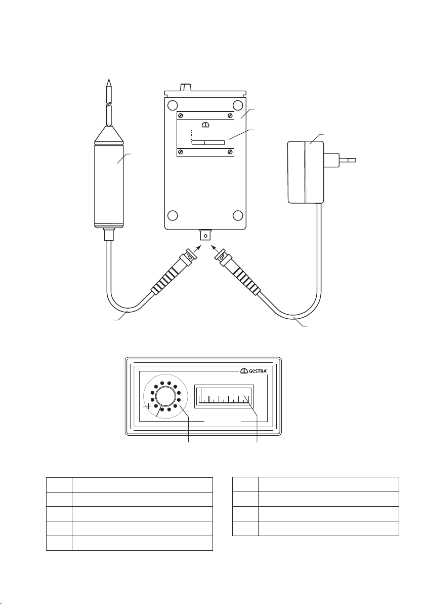
VKP 10
This steam trap testing equipment is referred to
below simply as equipment.
This Installation & Operating Manual is intended
for all persons bringing this equipment into ser-
vice, and operating, using, servicing, cleaning or
disposing of the equipment. In particular, the In-
stallation & Operating Manual is aimed at service
technicians, trained specialist personnel, and
qualified and authorised operating personnel.
Each of the above must have read and under-
stood the content of this Installation & Operating
Manual.
Following the instructions in the Installation &
Operating Manual helps to avoid danger and
increases the reliability and service life of the
equipment. In addition to the instructions in this
Installation & Operating Manual, compliance with
the applicable binding rules on accident preven-
tion in the country and location of use, and with
the generally recognised technical regulations for
safe and proper working, is essential.
Please also read and follow the instructions in
the manufacturers' operating manuals for the
data collector, particularly the safety notes.
Availability
Always keep this Installation & Operating Manual
in the leather bag for the equipment. Make sure
that the Installation & Operating Manual is avail-
able to the operator.
The Installation & Operating Manual is part of the
equipment package. Hand over this Installation
& Operating Manual if you sell or pass on the
equipment to a third party.
Formatting features in the
document
Different types of information in the Installation
& Operating Manual are formatted in different
ways.
This helps you to distinguish easily between the
following types of information:
Normal text
Cross references
◗Lists
◗Bullet points in lists
➢Action to be taken.
These tips contain additional informa-
tion, e.g. about cost-efficient use of the
equipment.
Security
Usage for the intended purpose
The steam trap testing equipment VKP 10 is used
for testing steam traps. Do not use or operate the
steam trap testing equipment VKP 10 in poten-
tially explosive atmospheres.
Usage for the intended purpose also includes
reading and adhering to all instructions in this
manual, particularly the safety notes.
Use for the intended purpose also includes
compliance with all the instructions given in the
manufacturers' operating manuals for the data
collector.
This applies in particular to the safety notes.
Any other use of the equipment shall be consid-
ered as improper use.
The following usages in particular shall be con-
sidered as improper use:
◗The use of equipment in potentially explosive
atmospheres without explosion protection
◗The use of the equipment by untrained
personnel
3
Vorwort
Diese Betriebsanleitung hilft Ihnen beim
bestimmungsgemäßen, sicheren und
wirtschaftlichen Gebrauch des folgenden
Prüfgeräts:
VKP 10
Dieses Prüfgerät für Kondensatableiter wird im
Folgenden kurz Gerät genannt.
Diese Betriebsanleitung wendet sich an jede
Person, die dieses Gerät in Betrieb nimmt, betreibt,
bedient, wartet, reinigt oder entsorgt. Die
Betriebsanleitung richtet sich insbesondere an
Kundendienst-Monteure, ausgebildetes
Fachpersonal und das qualifizierte und autorisierte
Betriebspersonal.
Jede dieser Personen muss den Inhalt dieser
Betriebsanleitung zur Kenntnis genommen und
verstanden haben.
Das Befolgen der Anweisungen in der
Betriebsanleitung hilft Gefahren zu vermeiden und
die Zuverlässigkeit und die Lebensdauer des Geräts
zu erhöhen. Beachten Sie außer den Hinweisen in
dieser Betriebsanleitung unbedingt die im
Verwenderland und an der Einsatzstelle geltenden
verbindlichen Regelungen zur Unfallverhütung sowie
die anerkannten technischen Regelungen für
sicherheits- und fachgerechtes Arbeiten.
Beachten und befolgen Sie auch die Hinweise in der
Betriebsanleitung des Herstellers zum
Datensammler, insbesondere die
Sicherheitshinweise.
Verfügbarkeit
Bewahren Sie diese Betriebsanleitung immer in
der Ledertasche für das Gerät auf. Stellen Sie
sicher, dass die Betriebsanleitung für den
Bediener verfügbar ist.
Die Betriebsanleitung ist Bestandteil des Geräts.
Liefern Sie diese Betriebsanleitung mit, wenn Sie
das Gerät verkaufen oder in anderer Weise
weitergeben.
Gestaltungsmerkmale im Text
Verschiedene Elemente der Betriebsanleitung sind
mit festgelegten Gestaltungsmerkmalen versehen.
So können Sie die folgenden Elemente leicht
unterscheiden:
normaler Text
Querverweise
Aufzählungen
Unterpunkte in Aufzählungen
Handlungsschritte.
Diese Tipps enthalten zusätzliche
Informationen, wie besondere Angaben
zum wirtschaftlichen Gebrauch des Geräts.
Sicherheit
Bestimmungsgemäßer Gebrauch
Das Prüfgerät für Kondensatableiter VKP 10
dient zum Prüfen von Kondensatableitern.Das
Prüfgerät für Kondensatableiter VKP 10 darf
nicht im explosionsgefährdeten Bereich betätigt
oder betrieben werden.
Zum bestimmungsgemäßen Gebrauch gehört auch
das Beachten und Befolgen aller Angaben in dieser
Anleitung, insbesondere der Sicherheitshinweise.
Das Beachten und Befolgen aller Angaben in der
Betriebsanleitung zum Datensammler gehört
ebenfalls zum bestimmungsgemäßen Gebrauch.
Dies gilt insbesondere für die darin enthaltenen
Sicherheitshinweise.
Jeder andere Gebrauch des Geräts gilt als
bestimmungswidrig.
Insbesondere folgender Gebrauch gilt als
bestimmungswidrig:
der Einsatz eines nicht explosionsgeschützten
Geräts im explosionsgefährdeten Bereich
der Einsatz des Geräts durch nicht
eingewiesenes Personal

4
Basic safety notes
Risk of explosion
◗Do not use the equipment in potentially
explosive atmospheres.
Risk of serious injury
◗Make sure that all equipment components are
free of damage.
◗There is a risk of electric shocks when per-
forming measurements on live valves. Make
sure that the valves to be tested are free of
voltage.
◗The valves to be tested are pressurised and
hot. Only perform tests when the following
conditions are satisfied:
◗Avoid skin contact with the valve to be tested
or other system parts.
◗Wear suitable protective clothing during all
measurements.
◗Ensure that there is no escaping fluid around
the valve to be tested.
◗There is a risk of electric shocks when han-
dling defective components.
◗Never open the components of the equip-
ment.
◗Never used damaged components.
◗Make sure that the cables used to charge the
equipment are in perfect condition before-
hand.
Information on property damages
or malfunctions
◗Sudden or strong changes in temperature can
lead to condensate build-up in the equipment.
◗Following temperature changes, leave the
equipment switched off until the equipment
temperature acclimatises to the ambient
temperature.
◗Allow the device to dry out fully in the
event of condensate build-up.
◗There is a risk of malfunctions and dam-
age to electronic components due to static
charges.
Wear electrically insulating shoes when
performing measurements.
◗There is a risk of malfunctions and damage to
electronic components due to incorrect han-
dling.
Never open the components of the equip-
ment.
◗Incorrect placement of the sound probe can
lead to inaccurate measurement results. Only
apply the sensor tip to a bare metallic sur-
face.
◗Performing measurements at various loca-
tions on a valve can lead to measurement
errors. Always apply the sensor tip to the
same measuring point. Apply the sensor tip
vertically to the surface of the valve.

5
Personnel qualifications
Specialist personnel must be familiar with and
have experience in the following areas:
◗Locally applicable explosion & fire protection
and occupational health & safety provisions
◗Work on pressure equipment
◗Working with hazardous (hot or pressurised)
fluids
◗All information in this Installation & Operating
Manual and other applicable documentation
◗Working with mobile end devices
◗Analysing and interpreting steam trap test
results
Protective clothing
The required protective clothing depends on the
regulations at the place of work and the media
used. Information on suitable protective clothing
and PPE can be found in the safety data sheet of
the fluid used.
The protective clothing basically consists of the
following items:
◗Safety helmet
◗Safety boots
◗Protective gloves
◗Safety goggles
Ear protectors may also be necessary, depending
on the noise level of the plant and the locally
applicable regulations.
Eye protection may also be necessary, depend-
ing on the fluid used in the plant and the locally
applicable regulations.
Formatting features for
warnings in the document
DANGER
Instructions with the word DANGER warn
of a dangerous situation that result in
death or serious injury.
WARNING
Instructions with the word WARNING
warn of a dangerous situation that may
possibly result in death or serious injury.
CAUTION
Instructions with the word CAUTION warn
of a situation that may result in minor or
moderate injury.
Formatting features for
warnings of property damages
Attention!
This information warns of a situation
resulting in property damage.
6
Gestaltungsmerkmale von
Warnhinweisen im Text
GEFAHR
Hinweise mit dem Wort GEFAHR warnen
vor einer gefährlichen Situation, die zum
Tod oder zu schweren Verletzungen führt.
WARNUNG
Hinweise mit dem Wort WARNUNG warnen
vor einer gefährlichen Situation, die
möglicherweise zum Tod oder zu schweren
Verletzungen führen kann.
VORSICHT
Hinweise mit dem Wort VORSICHT warnen
vor einer Situation, die zu leichten oder
mittleren Verletzungen führen kann.
Gestaltungsmerkmale für
Hinweise auf Sachschäden
Achtung!
Diese Hinweise warnen vor einer Situation,
die zu Sachschäden führt.
Beschreibung
Lieferumfang und
Gerätebeschreibung
Lieferumfang
Die Komponenten des Geräts werden in einer
Ledertasche geliefert. Vor dem Einsatz müssen
Sie die Komponenten verbinden und die Akkus
aufladen.
Folgende Bestandteile sind im
Lieferumfang enthalten
Anzeigegerät
Akku (im Anzeigegerät fest installiert)
Schallaufnehmer inklusive Kabel
Ledertasche
Ladegerät inklusive Kabel
Bedienungsanleitung

6
Description
Product package and
description of equipment
Scope of supply
The equipment components are delivered in a
leather bag. You must connect the components
and charge the batteries prior to use.
The following components are included in de-
livery
◗Display device
◗Storage battery (installed in the display
device)
◗Sound probe and cable
◗Leather bag
◗Battery charger and cable
◗Operating manual

7
Equipment specification
VKP 10
No. Designation or meaning
1 Display device
2 Name plate
3, 4 Battery charger and cable
5, 6 Sound probe and cable
No. Designation or meaning
6 Sound probe
7
Rotary switch for sensitivity setting
8 Indicator
Herst. GESTRA AG, Bremen
Typ Vapophone VKP 10
F.Nr. ...............................
Prüfer
:
:
:
:
®
MADE BY GESTRA
VAPOPHONE VKP 10
®
10
9
8
7
6
5
4
3
2
1
0
TEST
0 2 4 6 8 10
1
2
6
3
54
78

8
Task and function
Task
The testing equipment VKP 10 is used to test and
analyse steam traps of all types.
The testing equipment consists of a display
device and a sound probe.
Function
The testing equipment measures and analyses
ultrasonic vibrations that occur when steam
flows through functioning steam traps. The ul-
trasonic vibrations are transferred to the tip of
the sensor by pressing the sound probe to the
specified point of reference on the trap body.
The ultrasonic vibrations are then converted
into electric pulses and indicated by the display
device. The test equipment VKP 10 signals only
vibrations within 40 – 60 kHz, as these frequen-
cies constitute the usual vibration range associ-
ated with flowing steam. The user evaluates the
sensed ultrasonic vibrations as part of the com-
parison measurement carried out for reference.

9
Storing and transporting the
equipment
➢Install the equipment in the pipe.
Storing the equipment
➢Store the equipment solely in the following
conditions:
◗The equipment and all components must be
protected against jolts and impacts.
◗Only store the device in enclosed areas.
◗Observe the conditions indicated in the tech-
nical data.
➢Make sure that these conditions are constant-
ly maintained throughout storage.
➢Please contact the manufacturer if you wish
to store the equipment in different conditions.
Transporting the equipment
➢Maintain the same conditions during transport
that were in place during storage.
➢Observe the conditions indicated in the tech-
nical data during transport.
➢Transport the equipment in the leather bag
provided.
➢Transport the equipment at the location of
use in a way that protects it against falling
and impacts.
➢Observe the international rules on transport-
ing Ni-Cd batteries when transporting the
equipment.
Checking the equipment for damage
➢Remove the equipment from the transport
package.
➢Inspect the equipment for transport damage.
➢If you discover transport damage, please
contact the manufacturer.
Operation
Bringing the display device into
service
The device can be used for testing with and
without the leather bag. If using the leather bag,
open the locking strap on the base of the bag to
open the cable outlet.
➢Connect the cable of the sound probe 5 with
the display device 1.
➢Check the charge capacity of the battery.
➢Turn the rotary switch 7 to the symbol.
➢If the indicating meter 8 shows a value
less than “7”, recharge the battery.
Measurement preparations
Charging batteries
DANGER
Do not use the testing equipment VKP 10
in potentially explosive atmospheres!
Risk of explosion due to sparks during
charging!
Risk of explosion due to sparks during
connection!
6
Gestaltungsmerkmale von
Warnhinweisen im Text
GEFAHR
Hinweise mit dem Wort GEFAHR warnen
vor einer gefährlichen Situation, die zum
Tod oder zu schweren Verletzungen führt.
WARNUNG
Hinweise mit dem Wort WARNUNG warnen
vor einer gefährlichen Situation, die
möglicherweise zum Tod oder zu schweren
Verletzungen führen kann.
VORSICHT
Hinweise mit dem Wort VORSICHT warnen
vor einer Situation, die zu leichten oder
mittleren Verletzungen führen kann.
Gestaltungsmerkmale für
Hinweise auf Sachschäden
Achtung!
Diese Hinweise warnen vor einer Situation,
die zu Sachschäden führt.
Beschreibung
Lieferumfang und
Gerätebeschreibung
Lieferumfang
Die Komponenten des Geräts werden in einer
Ledertasche geliefert. Vor dem Einsatz müssen
Sie die Komponenten verbinden und die Akkus
aufladen.
Folgende Bestandteile sind im
Lieferumfang enthalten
Anzeigegerät
Akku (im Anzeigegerät fest installiert)
Schallaufnehmer inklusive Kabel
Ledertasche
Ladegerät inklusive Kabel
Bedienungsanleitung

10
Attention!
Condensate can accumulate in the
equipment when using it after sudden or
strong changes in temperature. This can
lead to malfunctions or damage.
➢Following temperature changes, leave
the equipment switched off until the
equipment temperature acclimatises to
the ambient temperature.
➢Do not charge the equipment in this
time.
Attention!
➢Charge the equipment fully before every
use.
Always charge the batteries before using the
equipment for the first time. It takes around 5
hours to recharge a fully depleted battery.
➢Connect the battery charger to the display
device and the electricity mains.
Performing a measurement
Checking the steam trap
DANGER
Risk of electric shock when checking a
live pipe.
➢Take suitable measures before starting
the check to ensure that no parts of the
pipeline are carrying voltage.
You can do this by earthing the pipeline, for
example.
➢Make sure that the measuring point is free of
paint or dirt.
➢Make sure that you use the same measuring
point as in previous measurements.
➢Mark the measuring point on the steam trap if
necessary.
Attention!
Incorrect placement of the sound probe
can lead to inaccurate measurement
results.
➢Only apply the tip of the sound probe to
a bare metallic surface.
➢Always apply the sensor tip to the same
measuring point.
➢Apply the sensor tip vertically to the
surface of the valve.
6
Gestaltungsmerkmale von
Warnhinweisen im Text
GEFAHR
Hinweise mit dem Wort GEFAHR warnen
vor einer gefährlichen Situation, die zum
Tod oder zu schweren Verletzungen führt.
WARNUNG
Hinweise mit dem Wort WARNUNG warnen
vor einer gefährlichen Situation, die
möglicherweise zum Tod oder zu schweren
Verletzungen führen kann.
VORSICHT
Hinweise mit dem Wort VORSICHT warnen
vor einer Situation, die zu leichten oder
mittleren Verletzungen führen kann.
Gestaltungsmerkmale für
Hinweise auf Sachschäden
Achtung!
Diese Hinweise warnen vor einer Situation,
die zu Sachschäden führt.
Beschreibung
Lieferumfang und
Gerätebeschreibung
Lieferumfang
Die Komponenten des Geräts werden in einer
Ledertasche geliefert. Vor dem Einsatz müssen
Sie die Komponenten verbinden und die Akkus
aufladen.
Folgende Bestandteile sind im
Lieferumfang enthalten
Anzeigegerät
Akku (im Anzeigegerät fest installiert)
Schallaufnehmer inklusive Kabel
Ledertasche
Ladegerät inklusive Kabel
Bedienungsanleitung

11
Performing measurements
Before checking steam traps, make sure that the
measurement sensitivity of the VKP 10 has been
selected in advance using the rotary switch 7.
The switch position “10” indicates the highest
level of sensitivity. Different steam trap types
generate varying sound levels, even when the
loss of steam and operating conditions are iden-
tical. We recommend the switch position “8” for
GESTRA type-BK steam traps and position “7” for
type-MK models.
Lightly press the sound probe against the surface
of the steam trap. Always place the sound probe
at the same location on the housing when testing
steam traps of the same type. This makes it pos-
sible to compare the steam traps and determine
any changes when repeating the tests.
Steam traps operating continuously, and dis-
charging up to about 30 kg/hr of condensate
from steam pressures lower than 20 bar will
cause no or only a slight deflection of the indicat-
ing meter. Any steam loss is indicated by a pro-
portional meter deflection. The relation between
steam loss and meter deflection depends on the
steam trap type and the used measuring point
on the trap surface. Larger condensate flowrates
and higher service pressures result in louder
flow-generated noises, making it necessary to
reduce the sensitivity setting. To obtain meaning-
ful readings when using the VKP 10, log and use
installation-specific survey data and empirical
test values.
In practice, an exact quantification of the steam
loss is usually only of minor importance. Normal-
ly, an approximate value that allows the detection
of steam loss through steam traps at a tolerable
effort will suffice.
When checking the steam traps, set the rotary
switch to “7” or “8”. A continuous indication be-
tween 6 and 8 on the meter scale indicates that
the trap requires maintenance or replacement.
This indicates steam losses of 1 to 4 kg/hr.

12
When checking thermal steam traps, position the
sensor tip as follows:
◗At the transition between the cover and the
cover flange
◗On the side of the cover
Examples of measuring points on thermal steam
traps
When checking ball-float steam traps, position
the sensor tip as follows:
◗At the highest point of the cover
◗On the side of the cover
Bei thermischen Kondensatableitern Siepositionieren
die :Messspitze
im Übergangsbereich zwischen Haube und
Haubenflansch
seitlich an der Haube
Beispiele fürAnsetzpunkte bei thermischen
Kon densatableitern
Bimetall-Ableiter TypBK15
Bimetall-Ableiter TypBK45
Thermischer Kapsel-Ableiter Typ MK 45
Bei Schwimmer ondensatableitern Sie diekpositionieren
Messspitze:
am höchsten Punkt der Haube
seitlich an der Haube
Beispiele fürAnsetzpunkte bei Schwimmerkondensatableiter
Schwimmerk 1, UNA 4ondensatableiter Typ UNA
Setzen Sie die Messspitze senkrecht auf die
Prüfstelle.
Schwimmerk 2ondensatableiter Typ UNA
Bimetallic steam trap type BK 15
Examples of measuring points on ball-float
steam traps
Bimetallic steam trap type BK 45
Thermostatic capsule steam trap type MK 45
Ball-float steam trap type UNA 1, UNA 4
Ball-float steam trap type UNA 2
Position the sensor tip perpendicular to the
measuring point.

13
Special information
Please take into account that ultrasonic sources
like pumps or steam reducing stations in the
proximity of the steam trap to be tested may
falsify the result. In this case, steam loss may be
indicated even though the traps operate correct-
ly. This can be verified by scanning the adjacent
pipelines. If the deflection remains unchanged
or increases, this must be attributed to a foreign
ultrasonic source. Switch off sound emitting plant
components, if possible.
Intermittently operating steam traps cause re-
current meter deflections which may even reach
the end of the scale. Thermostatic traps (with
bimetallic control or membrane regulators) may
operate within the specified pressure and flow-
rate range either continuously or intermittently. In
this case, steam loss can usually be excluded. A
recurrent meter deflection here indicates that the
steam trap is operating correctly.
Thermodynamically controlled steam traps
always operate intermittently. Any steam loss
rises with increasing lift frequency on this trap
type. Only a constantly large meter deflection can
clearly indicate steam loss.
Essentially the same considerations as men-
tioned for thermodynamic traps also apply in
the case of steam traps with open floats. How-
ever, inherent steam loss definitely occurs on
float-operated traps even when the trap operates
intermittently.
Before performing the tests, use the technical
plant data (service pressures, differential pres-
sures, flowrates etc.) to at least estimate wheth-
er the trap flowrate lies within the testable range.
After operation
➢Charge the equipment battery as described in
the section "Measurement preparations".
Servicing the equipment
The equipment does not require any particular
maintenance work.
Replacing the battery
Attention!
➢The battery (9 V, NiCd) of the display
device may only be replaced by the
manufacturer!
The service life of the permanently in-
stalled battery is five to seven years with
normal equipment use. If the battery is
defective, please send the equipment to
GESTRA, Bremen for the battery to be
replaced.
Removing external dirt
Attention!
Risk of damage to the device due to fluid
ingress.
➢Make sure that no fluid can penetrate
into the equipment.
➢Only clean using damp cloths.
➢Remove dirt from the equipment with clean
water and a lint-free cloth.
➢Remove stubborn dirt with a cleaning agent
suitable for the material and a lint-free cloth.
Checking parts for damage
➢Check that all equipment components are in
perfect condition before and after use.
➢Do not bring damaged components into ser-
vice.
➢Replace any damaged components.

14
Equipment maintenance and installing spare parts
Any defective components must be replaced.
No. Designation Stock code
1 Display device1)
6 Sound probe1)
5 Sound probe cable BNC 100 321509
3, 4 Battery charger 100-240 V AC, 50/60 Hz and cable 321510
1) We recommend having the display device and sound probe recalibrated by the manufacturer after no
more than 2 years.
Taking out of service
Removing harmful substances
DANGER
For equipment used in contaminated
areas, there is a risk of serious or fatal
injury from harmful substances on the
equipment.
➢Only allow specialist personnel to per-
form work on contaminated equipment.
➢Wear the protective clothing specified for
the contaminated zone during all work.
➢Make sure that the equipment is fully
decontaminated before any work.
➢Follow the instructions for handling the
relevant harmful substances here.
Specialist personnel must have knowledge and
experience in the following areas:
◗The applicable local regulations for handling
harmful substances
◗Special regulations for handling the harmful
substances present
◗The use of the prescribed protective clothing
Attention!
Risk of environmental damage due to
poisonous fluid residues.
➢Prior to disposal, make sure the equip-
ment is cleaned and free of any fluid
residues.
➢Dispose of all materials in accordance
with the regulations at the location of
use.
➢Remove all residues from the equipment.
➢Dispose of all residues in accordance with the
regulations at the location of use.
Dismantling the equipment
➢Charge the equipment if necessary.
➢Store the equipment as described under
"Storing the equipment".
6
Gestaltungsmerkmale von
Warnhinweisen im Text
GEFAHR
Hinweise mit dem Wort GEFAHR warnen
vor einer gefährlichen Situation, die zum
Tod oder zu schweren Verletzungen führt.
WARNUNG
Hinweise mit dem Wort WARNUNG warnen
vor einer gefährlichen Situation, die
möglicherweise zum Tod oder zu schweren
Verletzungen führen kann.
VORSICHT
Hinweise mit dem Wort VORSICHT warnen
vor einer Situation, die zu leichten oder
mittleren Verletzungen führen kann.
Gestaltungsmerkmale für
Hinweise auf Sachschäden
Achtung!
Diese Hinweise warnen vor einer Situation,
die zu Sachschäden führt.
Beschreibung
Lieferumfang und
Gerätebeschreibung
Lieferumfang
Die Komponenten des Geräts werden in einer
Ledertasche geliefert. Vor dem Einsatz müssen
Sie die Komponenten verbinden und die Akkus
aufladen.
Folgende Bestandteile sind im
Lieferumfang enthalten
Anzeigegerät
Akku (im Anzeigegerät fest installiert)
Schallaufnehmer inklusive Kabel
Ledertasche
Ladegerät inklusive Kabel
Bedienungsanleitung

15
Returning the equipment
You can return the equipment to your contractual
partner.
➢Register the return delivery with your con-
tractual partner before returning the equip-
ment.
➢Make sure that all harmful substances are
removed from the equipment.
➢Send the completed and signed decon-
tamination declaration with the equipment.
The decontamination declaration must be
attached to the packaging so that it is acces-
sible from outside.
➢Follow the instructions under "Transporting
the equipment".
➢Pack the equipment in its original packaging
or in a suitable transport package.
The transport packaging must protect the equip-
ment from damage in the same way as the orig-
inal packaging.
Disposal of the equipment
The equipment and its components contain elec-
tronic parts that must be disposed of separately.
➢Return the equipment in full to the manufac-
turer.
Technical data
Display device
Plastic housing with rotary switch and analogue
display.
Battery compartment in housing.
One socket for connecting the sound probe.
Protection rating IP 41.
Maximum admissible operating temperature: 70
°C.
Minimum admissible operating temperature: 0
°C.
Power supply
Power is supplied by a 9 V NiCd battery or the
battery charger.
Sound probe
The sound probe is supplied with power by the
battery of the display device.
Battery charger
100-240 V AC, 50/60 Hz
Output 5.8 - 11.6 V
Weight
Leather bag with contents approx. 2 kg.
Dimensions
Leather bag: 200 mm / 190 mm / 90 mm
Display device: 90 mm / 45 mm / 160 mm
(width / height / depth)
Manufacturer's Declaration
You can find details on the conformity of the
equipment in our Declaration of Conformity or
Manufacturer's Declaration.
You can download the latest Declaration of Con-
formity or Manufacturer's Declaration
at www.gestra.com or request it from the ad-
dress below:
GESTRA AG
Münchener Strasse 77
28215 Bremen
Germany
Phone +49 421 3503-0
Fax +49 421 3503-393
e-mail [email protected]
Web www.gestra.com
Modifications to the equipment not approved by
us will cause this Declaration to lose its validity.

16
818427-02/09-2021cm (803579-04)
·
GESTRA AG
·
Printed in Germany
GESTRA AG
Münchener Strasse 77
28215 Bremen
Germany
Tel. +49 421 3503-0
Fax +49 421 3503-393
E-mail [email protected]
Web www.gestra.com
You can find our authorised agents around the world at: www.gestra.com
Table of contents
Other GESTRA Test Equipment manuals