manuals.online logo
Brands
  1. Home
  2. •
  3. Brands
  4. •
  5. Bellman & Symfon
  6. •
  7. Transmitter
  8. •
  9. Bellman & Symfon BE9026 User manual

Bellman & Symfon BE9026 User manual

Buttons and connections
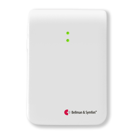
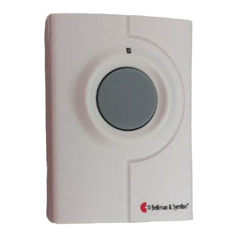
Visit telephone transmitter
Test / program buttons
2.5 mm ext. trig.
Pre-mounted telephone cord
BE9251 Mobile phone sensor
Doorbell push button
3.5 mm ext. trig. BE9023 Magnetic switchBE9026 Contact matLED lights
BE9253
BE1431
In the box
BE1431 Visit telephone transmitter
2
¯1.5 V AA alkaline batteries
Telephone cord and adapter
Screw and wall plug
Power and battery
Battery power
2¯1.5 V AA lithium or alkaline
type batteries
Power consumption
Active < 70 mA
Idle position < 15 μA
Operation time
Alkaline batteries ~ 5 years
Lithium batteries ~ 10 years
Accessories
BE9251 Mobile phone sensor
BE9023 Magnetic switch
BE9026 Contact mat
BE9253 Ext. trig. cable, 3.5 mm
Inputs
RJ11 analogue telephone input
2.5 mm external trigger input
3.5 mm external trigger input
Frequency and coverage
Frequency: 314.91 MHz, 433.92 MHz
or 868.30 MHz, depending on region
Coverage: 50 - 250 m, 55 - 273 yd.
depending on the radio frequency
and the building’s characteristics
Dimensions and weight
Height: 100 mm, 4.0"
Width: 65 mm, 2.6"
Depth: 27 mm, 1.1"
Weight: 120 g, 4.2 oz. incl. batteries
Activation
The test buttons
A landline telephone
A smartphone or tablet via the
mobile phone sensor
A contact mat or magnetic switch
A doorbell connected to the ext trig
Environment
For indoor use only
Technical specications
Using a mobile phone
1 Use for instance a mobile phone to call the landline
telephone. The top LED on the transmitter lights up in
green to show that an incoming call is detected.
2 The yellow Visit LED on the receiver lights up to show
that the radio signal was received. In addition, it starts to
sound, ash or vibrate depending on the receiver.
Note: If you have changed the signal pattern, it will react
in accordance with the table on the following spread.
Setting up the transmitter
1Remove the battery pull tab to start the unit.
Clean the wall with the wet wipe and remove the protective lm from the Velcro.
2Mount the transmitter on the wall. You can also use the supplied screw and plug.
3Connect the telephone adapter as shown below.
Note: The appearance of the adapter may dier with territory.
1 2
Testing the connection
Using the test button
1 Press both test buttons simultaneously on the telephone
transmitter. The top LED lights up in green to show that
a radio signal is being transmitted.
2 The yellow Visit LED on the receiver lights up to show
that the signal was received. In addition, it starts to
sound, ash or vibrate depending on the receiver.
Note: If you have changed the signal pattern, it will react
in accordance with the table on the following spread.
3
1 2 1 2
Visit telephone transmitter
Default signal pattern
When the telephone transmitter is activated by an incoming call or a triggered accessory, the following happens:
1The LED on the transmitter lights up to show that it’s signalling the receiver.
2The Visit LED on the receiver lights up and it starts to sound, ash or vibrate with a certain pace, called signal pattern.
The transmitter and the connected accessories determine the signal pattern. The default is as follows:
Transmitter Receiver signal pattern
Source LED LED Sound Vibration Flash
Landline phone Green, top Yellow light 1¯ring signal, low Medium Yes
Mobile phone sensor Green, top Yellow blinks 2¯ring signal, high Medium Yes
Other accessory Green, bottom Green light 1¯door chime, low Slow Yes
Changing the signal pattern
The transmitter controls the signal pattern. Open the transmitter front cover and move the
signal switches according to the table below to change it:
Transmitter Receiver signal pattern
Switch Source LED Sound Vibration Flash
Landline phone / test button Yellow light 1¯ring signal, low Medium Yes
Mobile phone sensor Yellow blinks 2¯ring signal, high Medium Yes
Other accessory Green light 1¯door chime, low Slow Yes
Landline phone / test button Yellow light 1¯ring signal, low Medium Yes
Mobile phone sensor Yellow blinks 2¯ring signal, high Medium Yes
Other accessory 2¯green blinks 2¯door chime, low Slow Yes
Landline phone / test button Yellow light 1¯ring signal, low Medium Yes
Mobile phone sensor Yellow blinks 2¯ring signal, high Medium Yes
Other accessory 3¯yellow blinks 1¯ring signal, high Medium Yes
Landline phone / test button Yellow light 1¯ring signal, low Medium Yes
Mobile phone sensor Yellow blinks 2¯ring signal, high Medium Yes
Other accessory 2¯orange blinks Baby melody Fast Yes
Landline phone / test button 2¯yellow blinks 2¯ring signal, low Fast Yes
Mobile phone sensor Yellow light 1¯ring signal, low Medium Yes
Other accessory 3¯orange blinks Baby melody Fast Yes
Landline phone / test button 2¯yellow blinks 2¯ring signal, low Medium Yes
Mobile phone sensor Orange blinks Baby melody Fast Yes
Other accessory Green blinks 2¯door chime, high Slow Yes
Landline phone / test button Orange blinks Baby melody Medium Yes
Mobile phone sensor 3¯yellow blinks 1¯ring signal, high Medium Yes
Other accessory 2¯green blinks 2¯door chime, low Slow Yes
Landline phone / test button 3¯yellow blinks 1¯ring signal, high Medium Yes
Mobile phone sensor 2¯yellow blinks 2¯ring signal, low Medium Yes
Other accessory Green blinks 2¯door chime, high Slow Yes
On
O
Changing the radio key
If your Visit system is activated for no reason, there is probably a nearby system that triggers yours. In order to avoid radio
interference you need to change the radio key on all units. The radio key switches are located under the transmitter cover.
Here is how you change the radio key:
1Open the transmitter front cover and move any radio key switch to the up (on position) to
change the radio key. By default, all radio key switches are positioned down (o).
2Press and hold the test/function button on the receiver until the green and yellow Visit LEDs
blink alternately. Release the button.
3Press both test buttons simultaneously on the transmitter within 30 seconds to send the new radio key.
4All Visit LEDs on the receiver blink 5 times to show that the radio key has been changed. It then returns to normal mode.
Note: All Visit units must be set to the same radio key in order to operate as a group.
°5
Troubleshooting
On
O
If Try this
The LEDs blink in orange every minute Replace the batteries. Only use 1.5 V AA (LR6) lithium or alkaline batteries.
The transmitter LED lights up in green
but the receiver doesn’t respond
Check the the transmitter batteries and the receiver batteries and connections.
Move the receiver closer to the transmitter to make sure it’s within radio range.
Check that the units are set to the same radio key, see Changing the radio key.
The transmitter LED doesn’t light up
when the phone rings or when an
accessory is triggered
Press the test buttons on the transmitter. If the LED lights up in green, check all
connections. If the LED doesn’t light up in green, replace the batteries. Only use
1.5 V AA (LR6) lithium or alkaline batteries.
The transmitter LED doesn’t light up
when I press the test buttons
Replace the batteries. Only use 1.5 V AA (LR6) lithium or alkaline batteries. If the
LED still doesn’t light up, contact your retailer for service information.
The receiver is activated for no
apparent reason
There is probably another Visit system installed nearby that triggers your
system. Change the radio key on all units, see Changing the radio key.
1 2 4
RADIO KEY
On
O
Visit telephone transmitter
3

Other Bellman & Symfon Transmitter manuals
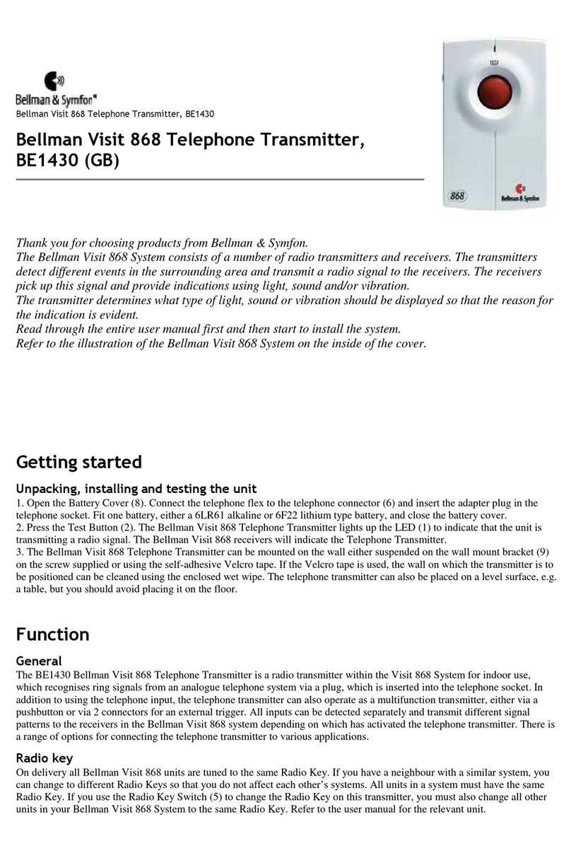
Bellman & Symfon Visit BE1282 User manual

Bellman & Symfon

Bellman & Symfon Visit BE1282 User manual

Bellman & Symfon BE1411 User manual

Bellman & Symfon

Bellman & Symfon BE1411 User manual

Bellman & Symfon BE1431 User manual

Bellman & Symfon

Bellman & Symfon BE1431 User manual

Bellman & Symfon BE1431 User manual

Bellman & Symfon

Bellman & Symfon BE1431 User manual

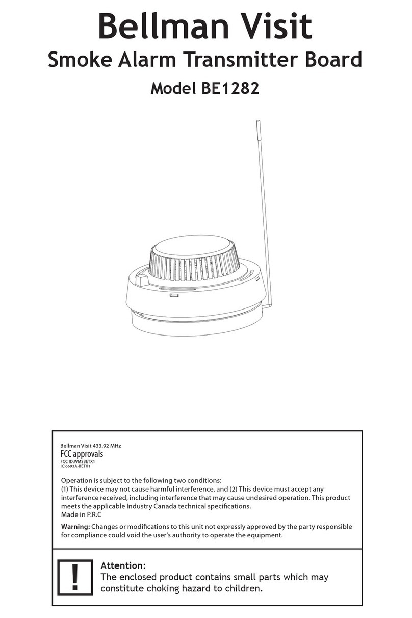
Bellman & Symfon Bellman Visit 868 User manual
Bellman & Symfon

Bellman & Symfon Bellman Visit 868 User manual

Bellman & Symfon 2APAKBE1240 User manual

Bellman & Symfon

Bellman & Symfon 2APAKBE1240 User manual

Bellman & Symfon BE1411 User manual

Bellman & Symfon

Bellman & Symfon BE1411 User manual

Bellman & Symfon BE1411-CO User manual

Bellman & Symfon

Bellman & Symfon BE1411-CO User manual

Bellman & Symfon BE1411 Setup guide

Bellman & Symfon

Bellman & Symfon BE1411 Setup guide

Bellman & Symfon BE1431 User manual

Bellman & Symfon

Bellman & Symfon BE1431 User manual
Bellman & Symfon BE1210 User manual

Bellman & Symfon

Bellman & Symfon BE1210 User manual

Bellman & Symfon BE1490 User manual

Bellman & Symfon

Bellman & Symfon BE1490 User manual

Bellman & Symfon BE1431 User manual

Bellman & Symfon

Bellman & Symfon BE1431 User manual

Bellman & Symfon BE1411 Assembly instructions

Bellman & Symfon

Bellman & Symfon BE1411 Assembly instructions

Bellman & Symfon BE1431 User manual

Bellman & Symfon

Bellman & Symfon BE1431 User manual

Bellman & Symfon BE1431 Assembly instructions

Bellman & Symfon

Bellman & Symfon BE1431 Assembly instructions

Bellman & Symfon VISIT BE1420 User manual

Bellman & Symfon

Bellman & Symfon VISIT BE1420 User manual

Bellman & Symfon BE1490 User manual

Bellman & Symfon

Bellman & Symfon BE1490 User manual

Bellman & Symfon BE1411 User manual

Bellman & Symfon

Bellman & Symfon BE1411 User manual

Bellman & Symfon Bellman Visit BE1023 User manual

Bellman & Symfon

Bellman & Symfon Bellman Visit BE1023 User manual

Bellman & Symfon BE1431 User manual

Bellman & Symfon

Bellman & Symfon BE1431 User manual

Bellman & Symfon Bellman Visit BE1023 User manual

Bellman & Symfon

Bellman & Symfon Bellman Visit BE1023 User manual

Bellman & Symfon BE1431 User manual

Bellman & Symfon

Bellman & Symfon BE1431 User manual

Bellman & Symfon BE1520 User manual

Bellman & Symfon

Bellman & Symfon BE1520 User manual
Popular Transmitter manuals by other brands
Beyerdynamic Unite TH quick start guide

Beyerdynamic

Beyerdynamic Unite TH quick start guide

CYP CH-1527TXV Operation manual

CYP

CYP CH-1527TXV Operation manual

AssetScan ASM01 Hardware Setup Instructions

AssetScan

AssetScan ASM01 Hardware Setup Instructions

Kingspan SENSiT quick start guide

Kingspan

Kingspan SENSiT quick start guide

Conrad 20 51 55 operating instructions

Conrad

Conrad 20 51 55 operating instructions

YOKOGAWA YTA610 user manual

YOKOGAWA

YOKOGAWA YTA610 user manual

Siemens SITRANS L operating instructions

Siemens

Siemens SITRANS L operating instructions

Vaisala CARBOCAP GMT220 SERIES user guide

Vaisala

Vaisala CARBOCAP GMT220 SERIES user guide

Endress+Hauser CM14-AAK operating instructions

Endress+Hauser

Endress+Hauser CM14-AAK operating instructions

AAS HD-SDE-SEDK user manual

AAS

AAS HD-SDE-SEDK user manual

THOMSON VS 540 CAU manual

THOMSON

THOMSON VS 540 CAU manual

Lectrosonics SMDa instruction manual

Lectrosonics

Lectrosonics SMDa instruction manual

BWI Eagle AIR-EAGLE SR PLUS manual

BWI Eagle

BWI Eagle AIR-EAGLE SR PLUS manual

Siemens RPT installation instructions

Siemens

Siemens RPT installation instructions

Verint nextiva s17xxe series user guide

Verint

Verint nextiva s17xxe series user guide

NTT docomo hitoe instruction manual

NTT docomo

NTT docomo hitoe instruction manual

Foxtech XLINK-30 user manual

Foxtech

Foxtech XLINK-30 user manual

Ebode TPC Quick installation

Ebode

Ebode TPC Quick installation

manuals.online logo
manuals.online logoBrands
  • About & Mission
  • Contact us
  • Privacy Policy
  • Terms and Conditions

Copyright 2025 Manuals.Online. All Rights Reserved.