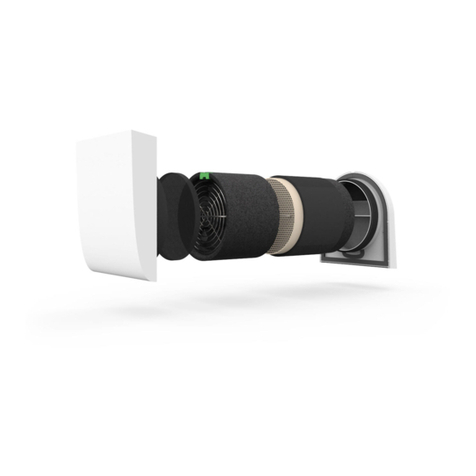
getAir SmartFan XR User manual

SmartFan XR
Installation and operating instructions
v 1.0_03/2017 EN

getAir GmbH & Co. KG
Krefelder Straße 670 | D-41066 Mönchengladbach
T +49 2161 990 950 | F +49 2161 990 959 9
info@getair.eu | www.getair.eu
All rights reserved.
These instructions have been compiled with the greatest care. Nevertheless, the publisher will accept no liability for
any damage resulting from missing or incorrect details therein. We reserve the right to make partial or entire changes
to these instructions at any time without prior announcement. All information contained in these documents is the
property of getAir GmbH & Co. KG. Any publishing thereof, whether in part or in whole, requires the written consent of
getAir GmbH & Co. KG. Copying the instructions within the same company for the purpose of evaluating the product or
for other product-related uses is permitted and not subject to prior approval.
© 2017 getAir GmbH & Co. KG
DE 2

3 DE
Content
1 General remarks..................................................................................................................................4
1.1 Usage.............................................................................................................................................4
1.2 Safety information .....................................................................................................................4
1.3 Installation prerequisites..........................................................................................................5
1.4 Rated airow volumes pursuant to DIN 18017 Part 3.......................................................5
1.5 Air inows and outows ...........................................................................................................6
1.6 Connection to the building‘s piping system.........................................................................6
1.7 Piping system..............................................................................................................................6
1.8 Plan for dimensioning the riser pipes....................................................................................7
2 Installation preparations ...................................................................................................................9
2.1 Contents .......................................................................................................................................9
2.2 Dimensions................................................................................................................................10
2.3 Versions with re protection according to DIN 18017 Part 3........................................11
3 Electrical installation........................................................................................................................12
3.1 Electrical cabling ......................................................................................................................12
3.2 Control module.........................................................................................................................12
3.3 Control module wiring diagrams..........................................................................................13
4 Installation ..........................................................................................................................................19
4.1 Installing the ush-mounted casing....................................................................................19
4.1.1 Installation using a mounting clamp ................................................................................19
4.1.2 Installation without the mounting clamp ....................................................................... 20
4.1.3 Fire protection outside duct walls with a shut-off device.......................................... 21
4.1.4 Fire protection outside duct walls without a shut-off device.................................... 21
4.1.5 Second room installation................................................................................................... 22
4.2 Installing the fan element ..................................................................................................... 22
4.3 Installing the surface-mounted fan.................................................................................... 24
5 Maintenance...................................................................................................................................... 26
5.1 Maintenance intervals............................................................................................................ 26
5.2 Maintenance instructions..................................................................................................... 26
5.2.1 Filter maintenance............................................................................................................... 27
5.2.2 Maintenance of the Type BU re protection device .................................................... 27
5.2.3 Maintenance of the Type BA shut-off device................................................................ 28
6 Disposal.............................................................................................................................................. 28
7 Technical data................................................................................................................................... 29
8 EC Conformity declaration ............................................................................................................ 31
9 Registration numbers ..................................................................................................................... 31
10 Warranty........................................................................................................................................... 32
11 Attachment...................................................................................................................................... 34

DE 4
1 General remarks
1.1 Usage
The units are designed for ventilating living rooms, wetrooms and kitchens pursuant to DIN
18017 Part 3. Their use is limited to the described use cases and only in association with the
recommended components listed in this document. Other usages are not permitted. The system
is unsuitable for extracting smoke or drying buildings, for rooms containing aggressive and/or
caustic gases or extreme levels of dust.
To guarantee the fault-free and safe use of the system, it is vital to ensure appropriate transport
and storage, professional planning and installation, as well as proper operation and maintenance.
Modications and recongurations of the unit / system are not permitted. The use of accessories
which have not been ofcially recommended is not allowed and will lead to a loss of warranty.
Before beginning with the installation, the positioning of the units needs to be properly planned.
During planning, installation and operation, all relevant requirements, building and re protection
regulations and accident prevention regulations are to be complied with. In the planning phase,
details need to be checked with the respective chimney sweep or ventilation expert.
1.2 Safety information
Attention is to be paid to the safety information contained in these instructions for installing
and operating the systems. Before any work is carried out on them, the instructions and safety
information are to be read carefully in full. Non-compliance with the safety information can lead
to harm/damage to persons and/or equipment.
Assembly, electrical installation and system start-up should only be performed by skilled per-
sons. These are people with relevant safety training and qualied to install, commission and label
equipment, systems and cabling in accordance with current safety standards.

5 DE
The following list contains descriptions of the symbols and terms used in these instructions:
Hazard symbol
Caution This hazard symbol warns about the
danger of injury.
Electricity This hazard symbol warns about the danger
of electrocution.
Warning symbol Please
note
This warning symbol indicates important
information
1.3 Installation prerequisites
To achieve the designed performance, proper installation, correct air outow positioning and
adequate inows must be ensured.
When using the system in a room with a replace, adequate inows of air must be guaranteed
under all operating circumstances.
The units are IPX5-rated (water jet protected) and can thus be installed in wetrooms. They are
rated as a Class II appliance and comply with Directive
89/336/EEC.
Deviating versions and unfavourable installation and operating conditions can lead to a reduction
in the rated airow volume. Pursuant to DIN 18017 Part 3, section 3.1.3., the airow volume may
be up to 15% under the rated airow volume when several ventilation units are operated serially
and at the same time and/or when they are inuenced by external conditions.
1.4 Rated airflow volumes pursuant to DIN 18017 Part 3
Ventilation units for use in ventilating bathrooms (with or without WCs) may, dependent on the
version and mode of operation, be designed for the following minimum airow volumes:
40 m³/h This volume must be extracted within a period of at least 12 hours a day.
60 m³/h The airow volume may be reduced to 0 m³/h, insofar as it is ensured that, each time the unit
is switched off, a further 5 m³ of air is extracted from the room in question by the system.

DE 6
1.5 Air inflows and outflows
Every interior room needing to be ventilated must have an unobstructed opening with a section of
150 cm² through which air can ow. The exhaust should be close to the ceiling, and lead into the
riser pipe. In bathrooms, the air must be directed in such a way that the airow speed does not
exceed 0.2 m/s in places where bathrooms occupants are likely to be.
1.6 Connection to the building‘s piping system
Attach the 75mm alu-ex pipe to the pipe junction and x with textile or cold welding tape. The
bending radius must not be lower than the diameter. To prevent corrosion, you must insulate the
connecting pipe with suitable foil (e.g. PE foil) between the pipe and the wall.
1.7 Piping system
The riser pipe with its required junctions must be dimensioned according to the number of oors
and the number of units with the aid of the plan below. Deformations, cross-section restrictions or a
discharge pipe above the uppermost unit of more than 1.5 m lead to increased pressure losses, which
must be compensated by the riser pipes having a larger diameter.
When one of the main pipes is not completely vertical, you must provide proof that the require-
ment stated in DIN 18 0 17 Part 3, section 3.1.3, third sentence, has been met. When dimensioning
the main pipe, you must base your calculation on the assumption that all fans are operating at
full power at the same time.
Pursuant to DIN 18 0 17 part 3, section 3.9, exhaust riser pipes must be tight, secure and, when
servicing more than two full oors, be made of re-resistant material (class A under DIN 4102).
They must be designed / insulated in such a way that damage from condensate is prevented. The
discharge pipe must exit the building above the roof.
To prevent noise being transmitted, the main pipe must be xed in place using noise-absorbing
pipe clamps.
The main pipes should have a sufcient number of sealed openings to allow them to be easily
cleaned. Screw-in cleaning caps are not permitted.
The installation of the ventilators must comply with the building acoustic requirements set forth
in DIN 4109.
A maximum of two fans per oor may be connected to the same main riser. A unit used to ventila-
te a bathroom and WC must not be used to ventilate any other rooms in an apartment.

7 DE
1.8 Plan for dimensioning the riser pipes
Preconditions: 2.75 m ceiling height, 1.50 m roof exit
Flush-mounted units
2 units per oor
Airow volume 60 m³/h
Pressure difference 118 Pa
1 unit per oor
Airow volume 60 m³/h
Pressure difference 118 Pa
100 125 140 160 180 200 225 250 280
1
2
3
4
5
6
7
8
9
10
11
12
13
14
15
16
17
1
2
3
4
5
6
7
8
9
10
11
12
13
14
15
16
17
Nominal pipe diameter
Number of floors
100 125 140 160 180 200 225 250
1
2
3
4
5
6
7
8
9
10
11
12
13
14
15
16
17
1
2
3
4
5
6
7
8
9
10
11
12
13
14
15
16
17
18 18
19 19
20 20
Nominal pipe diameter
Number of floors
2 units per oor
Airow volume 100 m³/h
Pressure difference 60 Pa
1 unit per oor
Airow volume 100 m³/h
Pressure difference 60 Pa
100 125 140 160 225 280
1
2
3
4
5
6
7
8
1
2
3
4
5
6
7
8
Nominal pipe diameter
Number of floors
100 125 140 160 180 200 225 280
1
2
3
4
5
6
7
8
9
10
11
12
1
2
3
4
5
6
7
8
9
10
11
12
Nominal pipe diameter
Number of floors

DE 8
Surface-mounted units
2 units per oor
Airow volume 60 m³/h
Pressure difference 88 Pa
1 unit per oor
Airow volume 60 m³/h
Pressure difference 88 Pa
100 125 140 160 180 200 225 250 280
1
2
3
4
5
6
7
8
9
10
11
12
13
14
15
16
17
1
2
3
4
5
6
7
8
9
10
11
12
13
14
15
16
17
Nominal pipe diameter
Number of floors
100 125 140 160 180 200 225 250
1
2
3
4
5
6
7
8
9
10
11
12
13
14
15
16
17
1
2
3
4
5
6
7
8
9
10
11
12
13
14
15
16
17
18 18
19 19
20 20
Nominal pipe diameter
Number of floors
2 units per oor
Airow volume 90 m³/h
Pressure difference 67 Pa
1 unit per oor
Airow volume 90 m³/h
Pressure difference 67 Pa
100 125 140 160 225 280
1
2
3
4
5
6
7
8
1
2
3
4
5
6
7
8
Nominal pipe diameter
Number of floors
100 125 140 160 180 200 225 250
1
2
3
4
5
6
7
8
9
10
11
12
13
14
15
16
17
1
2
3
4
5
6
7
8
9
10
11
12
13
14
15
16
17
18 18
19 19
20 20
Nominal pipe diameter
Number of floors

9 DE
2 Installation preparations
2.1 Contents
The casing for the ush-mounted unit is generally supplied without packaging to reduce waste.
The casing is made of silica bres or ABS / EPS and is supplied with a wet-proof plaster protec-
tion cover. A casing with an ancillary connection has an additional steel connector for a 75mm
alu-ex-pipe.
For a casing with built-in re protection, a shut-off device is located in the exhaust socket. It
consists of a trigger console with a fusible link and a shut-off element made of silica bres. The
shut-off device can be retrotted.
The carton containing the fan element for ush-mounted devices may also contain a control mo-
dule. As well as the lter bracket and lter (Class EU 2 under DIN 24185 Part 2) and the fan cover.
The surface-mounted unit consists of a base plate to which the fan is attached, a fan cover and
optionally a control module and xing material.
If the fan is kept in storage for a longer period, the following must be ensured to prevent damage:
• The storage place must not be subject to temperature uctuations, and must be dry and
protected from water and shaking.
• Make sure the fan is kept sealed in airtight packaging.

DE 10
2.2 Dimensions
Flush-mounting cases
270
072
85
Ø 74
255
255
85
Ø 74
270
072
85
Ø 74
255
255
85
Ø 74
Fan element Fan cover
223
322
78
260
254
55
260
254

11 DE
2.3 Versions with fire protection according to DIN 18017 Part 3
protection
BU
1
2
3
Fixing screw
Trigger console
Shut-off element
1
2
3
protection
protection
BA
1
1

DE 12
3 Electrical installation
3.1 Electrical cabling
The units are IPX5-rated (water jet protected) and can thus be installed in wetrooms. They are
rated as a Class II appliance and comply with Directive 89/336/EEC. No safety connection to
electrical earth (ground) is required.
Installation must provide for complete (all poles) disconnection from the mains and for a min. 3
mm contact opening width.
Please ensure compliance with all normal standards, safety requirements and technical connec-
tion requirements of your energy supplier.
Cables to be used:
• 3 x 1,5 NYM-J for Type G control modules
• 5 x 1,5 NYM-J for Type V direct control modules
• 7 x 1,5 NYM-J for Type V central control modules
3.2 Control module
Dependent on requirements and the selected type, the fans can be operated as follows:
1. Single-stage
• for direct demand-oriented venting
• for time-lag venting
• for interval-controlled venting
2. Multi-stage
• with high voltage control
• with base, partial or full load
• for time-lag venting
• for interval-controlled venting

13 DE
The second mains connection is for locally-connected partial load devices. The wiring diagrams
are to be found on each individual control module. Time lags and intervals are either set to stan-
dard settings or can be individually set. Multi-stage fans are connected via double-pole switches.
3.3 Control module wiring diagrams
Single room installation
Mains 230 V/50 Hz N
Wiring diagram no. 002
Mains 230 V/ 50 Hz L
Light fitting
Fan terminal block
Electrical connection
for types:
G 60 P
G 100 P
Fan
Motor
CMN
2 1 LS N
Double-pole
switch
Room 1
Electrical connection for types:
G 60 P
G 100 P
CMN21SLN
M
L
N
230 V/AC 50Hz
0,15 A
IP X5 CE

DE 14
Single room installation
Mains 230 V/50 Hz N
Wiring diagram no. 001
Mains 230 V/ 50 Hz L
Light fitting
Fan terminal block
Electrical connection
for types:
VN 60 P
VN 100 P
VNIE 60 P
VNIE 100 P
VNE 60 P
VNE 100 P
Fan
Motor
CMN
2 1 LS N
Double-pole
switch
Room 1
Electrical connection for types:
VN 60 P
VN 100 P
VNE 60 P
VNIE 100 P
CMN21SLN
M
L
N
230 V/AC 50Hz
0,15 A
IP X5 CE
VNE 60 P
VNE 100 P
Single room installation
Mains 230 V/50 Hz N
Wiring diagram no. 003
Mains 230 V/ 50 Hz L
Light fitting
Fan terminal block
Electrical connection
for types:
V 40 / 60 HS P
V 40 / 100 HS
V 60 / 100 HS
Fan
Motor
CMN
2 1 LS N
Double-
pole switch
Single-
pole switch
Room 1
Electrical connection for types:
V 40 / 60 HS P
V 40 / 100 HS
V 60 / 100 HS
CMN21SLN
M
L
N
Full load
Base load
230 V/AC 50Hz
0,15 A
IP X5 CE

15 DE
Single room installation
Mains 230 V/50 Hz N
Wiring diagram no. 009
Mains 230 V/ 50 Hz L
Light fitting
Fan terminal block
Electrical connection
for types:
VNE 40 / 60 HS P
Fan
Motor
CMN
2 1 LS N
Double-
pole switch
Single-
pole switch
Room 1
Electrical connection for types:
VNE 40 / 60 HS P
CMN21SLN
M
L
N
Full load
Base load
230 V/AC 50Hz
0,15 A
IP X5 CE
Single room installation
Mains 230 V/50 Hz N
Wiring diagram no. 004
Mains 230 V/ 50 Hz L
Light fitting
Fan terminal block
Electrical connection
for types:
V 40 / 60 / 100
VNE 40 / 60 / 100 P
Fan
Motor
CMN
2 1 LS N
Double-pole
switch
Single-pole
switch
Single-pole
switch
Full load Base load Partial load
Room 1
Electrical connection for types:
V 40 / 60 / 100
VNE 40 / 60 / 100 P
CMN21SLN
M
L
N
230 V/AC 50Hz
0,15 A
IP X5 CE
Full load
Base load
Part. load

DE 16
Second room installation
Mains 230 V/50 H N
Wiring diagram no. 005
Mains 230 V/ 50 Hz L
Fitting light
Fan terminal block
Electrical connection
for types:
G 60
G 100
Fan
Motor
CMN
2 1 LS N
Double-pole
switch
Double-pole
switch
Full load Full load
Room 1 Room 2
Fitting light
Electrical connection for types:
G 60
G 100
CMN21SLN
M
L
N
230 V/AC 50Hz
0,15 A
IP X5 CE
Second room installation
Mains 230 V/50 Hz N
Wiring diagram no. 006
Mains 230 V/ 50 Hz L
Light fitting
Fan terminal block
Electrical connection
for types:
Fan
Motor
CMN
2 1 LS N
Double-pole
switch
Double-pole
switch
Full load Full load
Room 1 Room 2
Light fitting
VN 30
VN 60
VN 100
VNIE 60
VNIE 100
VNE 60
VNE 100
VNB 60
VNB 100
Electrical connection for types:
VN 30
VN 60
VN 100
VNIE 60
VNIE 100
CMN21SLN
M
L
N
230 V/AC 50Hz
0,15 A
IP X5 CE
VNE 60
VNE 100
VNB 60
VNB 100

17 DE
Second room installation
Mains 230 V/50 Hz N
Wiring diagram no. 007
Mains 230 V/ 50 Hz L
Light fitting
Fan terminal block
Electrical connection
for types:
VN 30 / 60
VNB 30 / 60
VNE 30 / 60
VNE 30 / 100
VNIE 30 / 60
Fan
Motor
CMN
2 1 LS N
Double-pole
switch
Single-pole
switch
Full load Base load
Room 1
Light fitting
Double-pole
switch
Full load
Room 2
Electrical connection for types:
VN 30 / 60
VNB 30 / 60
VNE 30 / 60
VNE 30 / 100
VNIE 30 / 60
CMN21SLN
M
L
N
230 V/AC 50Hz
0,15 A
IP X5 CE
Full load
Base load
Second room installation
Mains 230 V/50 Hz N
Wiring diagram no. 008
Mains 230 V/ 50 Hz L
Light fitting
Fan terminal block
Electrical connection
for types:
VNE 30 / 60 / 100
VNE 20 / 30 / 100
Fan
Motor
CMN
2 1 LS N
Double-pole
switch
Single-pole
switch
Full load Base load
Room 1
Light fitting
Double-pole
switch
Full load
Room 2
Single-pole
switch
Partial load Electrical connection for types:
VNE 30 / 60 / 100
VNE 20 / 30 / 100
CMN21SLN
M
L
N
230 V/AC 50Hz
0,15 A
IP X5 CE
Full load
Base load
Part. load

DE 18
Second room installation
Mains 230 V/50 Hz N
Wiring diagram no. 010
Mains 230 V/ 50 Hz L
Light fitting
Fan terminal block
Electrical connection
for types:
G 30 / 60
G 30 / 100
Fan
Motor
CMN
2 1 LS N
Double-pole
switch
Single-pole
switch
Full load Base load
Room 1
Light fitting
Double-pole
switch
Full load
Room 2
Electrical connection for types:
G 30 / 60
G 30 / 100
CMN21SLN
M
L
N
230 V/AC 50Hz
0,15 A
IP X5 CE
Full load
Base load
Second room installation
Mains 230 V/50 Hz N
Wiring diagram no. 006
Mains 230 V/ 50 Hz L
Light fitting
Fan terminal block
Electrical connection
for types:
VNF 60
VNF 100
VNF 30 / 60
VNF 30 / 100
VNIEF 30 / 60
Fan
Motor
CMN
2 1 LS N
Double-pole
switch
Full load
Room 1
Light fitting
Double-pole
switch
Full load
Room 2
Hy
Electrical connection for types:
VNF 60
VNF 100
VNF 30 / 60
VNF 30 / 100
VNIEF 30 / 60
CMN21SLN
M
L
N
230 V/AC 50Hz
0,15 A
IP X5 CE
Hy

19 DE
4 Installation
The units can be installed and operated in any position, but the exhaust pipe must not face down-
wards. Flush-mounted units without re protection are not suitable for installing in ceilings. When
installing units with re protection, the exhaust pipe must face upwards.
4.1 Installing the flush-mounted casing
The metal frame must be ush with the plaster, meaning that the insertion made for the casing
must be at least 95mm deep (105 mm for a casing without re protection). A deeper insertion
or the mounting of tiles at a later time is no problem, as no connection is required between the
casing and the lter bracket. The lter bracket claws let it sit rmly both in the casing and in the
brickwork or plaster. When installing the casing, use a mortar belonging to Group II or III.
4.1.1 Installation using a mounting clamp
The mounting clamp must be shortened to the required size at the foreseen holes. Screw it on to
the casing. For a casing without re protection, screw anchors are provided.

DE 20
Now attach the mounting clamp and the casing to the ceiling or wall using the supplied screw
anchors.
Wall installation Ceiling installation
300 mm
25 mm
300 mm
25 mm
Push the alu-ex connector pipe onto the riser junction
and seal with textile or cold-shrink tape.
Push the electrical cables through the opening in the
casing and shorten to 50 cm.
4.1.2 Installation without the mounting clamp
The casing can be attached to the ceiling by using a
perforated steel band. Use the two screwholes next to
exhaust pipe.
Push the alu-ex connector pipe onto the connector
and seal with textile or cold welding tape.
Push the electrical cables through the opening in the casing and shorten to 50 cm.
Cable inlet ush-mounting
Other manuals for SmartFan XR
1
Table of contents
Other getAir Fan manuals