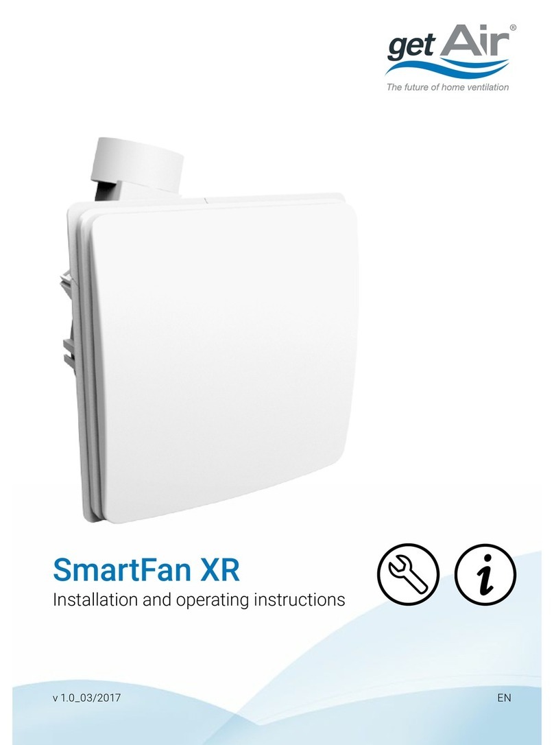
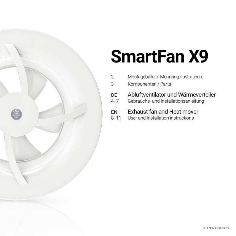
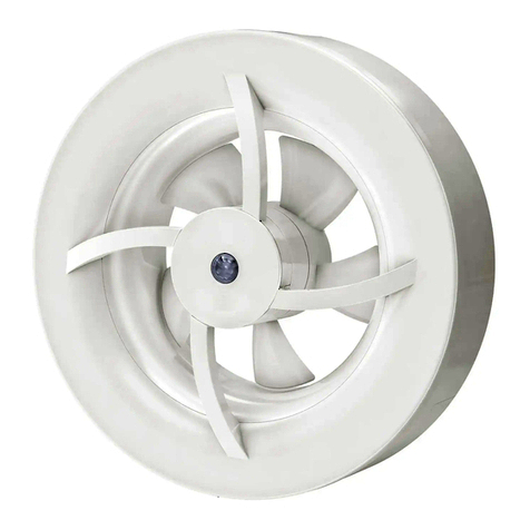
getAir SmartFan User manual

SmartFan
Installation and operating instructions
v 1.2_08/2016 EN

getAir GmbH & Co. KG
Krefelder Straße 670 | D-41066 Mönchengladbach
T +49 2161 990 950 | F +49 2161 990 959 9
info@getair.eu | www.getair.eu
All rights reserved.
These instructions have been compiled with the greatest care. Nevertheless, the publisher will accept
no liability for any damage resulting from missing or incorrect details therein. We reserve the right to
make partial or entire changes to these instructions without prior announcement.
All information contained in these documents is the property of getAir GmbH & Co. KG. Any publishing
thereof, whether in part or in whole, requires the written consent of getAir GmbH & Co. KG. Copying
the instructions within the same company for the purpose of evaluating the product or for other
product-related uses is permitted and not subject to prior approval.
© 2016 getAir GmbH & Co. KG
2SmartFan EN

3
EN SmartFan
Table of content
1 General remarks..........................................................................................................................4
2 System overview.........................................................................................................................6
2.1 Functioning .......................................................................................................................... 6
3 Installation preparations............................................................................................................8
3.1 SmartFan components......................................................................................................8
3.2 TOUCH control unit components ....................................................................................9
3.3 LED control unit components...........................................................................................9
3.4 Dimensions ........................................................................................................................10
3.5 Required tools....................................................................................................................10
3.6 Positioning..........................................................................................................................11
4 Electrical installation ................................................................................................................12
4.1 Installation recommendations for the control unit.....................................................13
4.2 Connection and wiring .....................................................................................................14
4.3 Setting the DIP switch......................................................................................................15
5 Installation..................................................................................................................................16
5.1 Making the hole in the wall .............................................................................................16
5.1.1 Use of a prefabricated installation block..........................................................16
5.1.2 Core-drilling a hole through the wall..................................................................17
5.2 Inserting the mounting tube ...........................................................................................18
5.3 Cabling ................................................................................................................................19
5.4 Installing the outside cover.............................................................................................19
5.5 Installing the heat exchanger unit..................................................................................20
5.6 Installing the fan unit........................................................................................................20
5.7 Inserting the inside cover ................................................................................................21
6 Operating the system...............................................................................................................22
6.1 SmartFan............................................................................................................................22
6.1.1 Shutting the inside cover.....................................................................................22
6.1.2 Opening the inside cover .....................................................................................23
6.2 TOUCH control unit...........................................................................................................24
6.2.1 Control screens .....................................................................................................24
6.2.2 System set-up........................................................................................................25
6.2.3 Operating modes and functions.........................................................................26
6.2.4 Further functions...................................................................................................27
6.3 LED control unit.................................................................................................................28
6.3.1 Controls...................................................................................................................28
6.3.2 Operating modes...................................................................................................28
6.3.3 Further functions...................................................................................................29
7 Cleaning and maintenance .....................................................................................................30
7.1 Maintenance interval........................................................................................................30
7.2 Maintenance instructions................................................................................................31
7.2.1 Filter maintenance................................................................................................31
7.2.2 Fan unit maintenance...........................................................................................32
7.2.3 Heat exchanger maintenance ............................................................................33
8 Troubleshooting ........................................................................................................................34
9 Disposal ......................................................................................................................................36
10 Technical data ..........................................................................................................................37
11 Energyefciencylabelandproductinformationsheet..........................................................39
12 Warranty .....................................................................................................................................43
13 Attachment.................................................................................................................................45

Though its contents have been checked for consistency with the described hard- and soft-
ware, deviations cannot be ruled out, meaning that no guarantee of complete consistency
can be given.
This documentation is updated on a regular basis. Necessary corrections and useful ad-
denda will always be included in subsequent versions.
They are also available at www.getair.eu.
4SmartFan EN
1 General remarks
1.1 Usage
The SmartFan is intended for use in the controlled ventilation of rooms in houses, apart-
ments,hotels, ofceandpublicbuildings.Itcanbe installedeither innew buildingsorin
existing buildings undergoing refurbishment and/or modernisation. SmartFan usage is
authorised solely in accordance with the described use cases and only in association with
components recommended by getAir GmbH & Co. KG and listed in this document. Other
SmartFan usages are not permitted. The system is unsuitable for extracting smoke or drying
buildings, for rooms containing aggressive and/or caustic gases or extreme levels of dust.
To guarantee the fault-free and safe use of the system, it is vital to ensure appropriate trans-
port and storage, professional planning and installation, as well as proper operation and
maintenance.Modicationsandrecongurationsoftheunit/systemarenotpermitted.
Before starting installation, the project needs to have been planned properly, detailing the
number and positioning of the ventilation units and their associated controls, and the venti-
lation principle applied (cross-ventilation, single room ventilation, air extraction).
Duringplanning,installationandoperation,allrelevantrequirements,buildingandreprotec-
tion regulations and accident prevention regulations are to be complied with. In the planning
phase, details need to be checked with the respective chimney sweep or ventilation expert.

5
EN SmartFan
1.2 Safety information
Attention is to be paid to the safety information contained in these instructions for instal-
ling and operating the control unit. Before any work is carried out on the unit / system, the
instructions and safety information are to be read carefully in full. Non-compliance with
the safety information can lead to harm/damage to persons and/or equipment.
Assembly, electrical installation and system start-up should only be performed by skilled
persons.Thesearepeoplewithrelevantsafetytrainingandqualiedtoinstall,commission
and label equipment, systems and cabling in accordance with current safety standards.
The following list contains descriptions of the symbols and terms used in these instructions:
Hazard symbol
Caution This hazard symbol warns about
the danger of injury.
Electricity This hazard symbol warns about
the danger of electrocution.
Warning symbol Please note This warning symbol indicates
important information.

6SmartFan EN
2 System overview
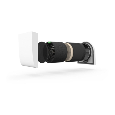
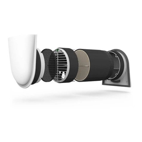
The SmartFan consists of acoustically optimised designer covers for inside (1) and out-
side(2)allowinganoptimalairow,alterunit(3),afanunit(4),aheatexchangerunit
(5) and an mounting tube (6). The SmartFan is always installed in an outside wall. The
mounting tube into which the fan and heat exchanger units are inserted is sealed inside
thewall.Theinsideandoutsidecoverscanbe ttedwithouttools.Theyconstitutethe
nishingelementsofthesystemandensureoptimalairow,therebyguaranteeingmore
efcientventilation.
2.1 Functioning
Wherever possible, SmartFans should be operated in pairs, i.e. with one unit blowing in
fresh air and the other expelling spent air. The units change direction concurrently after
50 - 70 seconds (depending on the selected fan speed). This allows a room to be properly
aired,balancingairinowandoutowinaccordancewithDIN1946-6.Theintegratedheat
exchangerextractsandstoresheatfromtheoutowingair.Whenthedirectionchanges
andfreshairissuckedin,itiswarmedbyowingovertheheatexchanger.Indoingso,the
SmartFan achieves a heat recovery rate of 91%.
1
3
4
5
6
2

7
EN SmartFan
Example of optimal ventilation
TO ENSURE PROPER VENTILATION THROUGHOUT A BUILDING (I.E. NOT JUST IN
ONE ROOM) IT IS IMPORTANT TO FORESEE FURTHER SUITABLE VENTILATION
OPENINGS, FOR INSTANCE SPACE UNDER DOORS (CA. 15 - 20 MM) OR THE
USE OF VENTILATION GRILLES.
Example for wet rooms
GENERALLY SPEAKING, WET ROOMS REQUIRE (1) TWO UNITS TO BE INSTALLED,
AND (2) PRECAUTIONS TO BE TAKEN THAT WET ROOM AIR DOES NOT MIX WITH
THE AIR OF OTHER ROOMS. THIS SYSTEM IS NOT SUITABLE FOR WET ROOMS
WITH NO OUTSIDE WALL.
WC
BATHROOM

8SmartFan EN
3 Installation preparations
Before starting installation, please check that all components are present, as otherwise it
will not be possible to complete the installation.
3.1 SmartFan components
Article name Item Content Numbers
Full SmartFan set
1SmartFaninsidecover+dustlter 1
2 SmartFan outside cover 1
3 SmartFan fan unit 1
4 SmartFan heat exchanger unit 1
5 Mounting tube 500 mm 1
6 Plastering covers 2
7 SmartFan cap for the inside cover 1
Article name Item Content Numbers
SmartFan
building shell set
2 SmartFan outside cover 1
5 Mounting tube 500 mm 1
6 Plastering covers 2
Article name Item Content Numbers
SmartFan
nishing set
1SmartFaninsidecover+dustlter 1
3 SmartFan fan unit 1
4 SmartFan heat exchanger unit 1
7 SmartFan cap for the inside cover 1
7

1
3
2
9
EN SmartFan
3.2 TOUCH control unit components
Article name Item Content Numbers
TOUCH control unit
1 TOUCH control screen 1
2 Frame 1
3 Control base 1
3.3 LED control unit components
Article name Item Content Numbers
LED control unit
1 LED control panel 1
2 Frame 1
3 Control base 1
1
3
2

10 SmartFan EN
3.4 Dimensions
3.5 Required tools
The following equipment is needed to install the SmartFan:
•CoredrillwithaØ162mmbit
•Sabresawforsawingplastic
•Mountingadhesive/sealanttoxthemountingtubeinplace
•2.5mmslotscrewdriver
•Hammerandchiselforcableducts/slits
•Deeppattressboxforushmounting
(single or double, dependent on the choice of installation)
198
45
199
>360
500
160
3
500
162
240
220

11
EN SmartFan
3.6 Positioning
The best position for the SmartFan is determined in the project planning phase. Please
pay attention to the minimum distances, as otherwise no guarantee can be given that the
units will function properly.
Minimum distance to the
ceiling and oor
The minimum distance to the ceiling must not be less
than300mm,andtotheoornotlessthan1000mm.
Minimum distance to other
objects (e.g. windows or doors)
or walls
The distance to other building elements such as
windows, doors or other walls should be at least
150 mm, both inside and outside.
Minimum distance between two
SmartFan units on the same
wall
The distance between two units, whether horizontally or
vertically, should not be less than 1000 mm.
Minimum distance between two
SmartFan units installed on two
neighbouring walls
When installing units on neighbouringwalls, make sure
that each unit is at least 1000 mm away from the other
wall. In addition, the diagonal distance between the two
units must not be less than 1400 mm.
> 300 mm
> 1000 mm
> 150 mm
> 1000 mm
> 1000 mm
> 1000 mm
> 1400 mm

12 SmartFan EN
4 Electrical installation
The SmartFan home ventilation system can only be used in conjunction with a TOUCH or
LED control unit.
The SmartFan is controlled via a BUS system, meaning that all units can be connected to the
control unit individually or serially. The control unit can be installed anywhere within a home‘s
electrical system. BUS signals can travel a maximum distance of 1000 m. 4-pole cables must
be used, whereby LiYY cables are recommended.
The control unit‘s socket is equipped with two rows of ports. Each can be used to connect
one series of SmartFan units. Should several series need to be connected, the bottom (larger)
row of ports or screw terminals can be used.
Example of the wiring of six SmartFans
The following table serves as a guide, showing the maximum length per segment (cable
length between two units) to ensure adequate supply voltage.
Cable diameter Segment length
0,25 mm² 40 m
0,5 mm² 70 m
0,75 mm² 100 m
230 V AC
Power supply
Segment

13
EN SmartFan
One power supply can serve up to six units. Once you exceed six SmartFan units, you will
need to install a further power supply unit. Further power supply units may also be connec-
ted directly to the control unit. However, when distances are long, these should be installed
asfarawayaspossiblefromtherstpowersupply.Careshouldbetakingwhendoingthe
wiring, as a false connection of the +42 V and earth cables can damage the power supply
units.
PLEASE NOTE: THE SMARTFAN FAN UNITS HAVE AN INTERNAL VOLTAGE
CONVERTER WHICH CONVERTS THE 42V INPUT VOLTAGE TO 12V.
4.1 Installation recommendations for the control unit
Install the control units at standard wall height. Both the TOUCH and LED control units can
be installed using a pattress box. The power supply can also be installed in the box.
THE INSTALLATION IS TO BE DONE IN SUCH A WAY THAT THE 42V OUTPUT
CABLE AND THE 230V INPUT CABLE ARE NOT ON THE SAME SIDE OF THE POWER
SUPPLY UNIT.
To avoid the use of a pattress box, you may also use a DIN Rail terminal box. However, such
a power supply requires a further cable duct for the cable to the fuse box.

14 SmartFan EN
4.2 Connection and wiring
Allelectricalworkmustbeperformedbyaqualiedelectrician.Makesurethatallwiring
is done correctly.
When connecting the control unit to the SmartFan unit, a 4-pin 3.50 mm connector plug
must be mounted on the cable. The connector must be wired as shown below. When
connecting the plug to the fan unit holder, the screws should point downwards. When
continuing the cable to a further SmartFan unit, the colours of the input and output wires
in the selected plug openings must match each other.
INCORRECT WIRING CAN CAUSE DAMAGE TO THE FAN UNIT.
Black
Red
Power
supply
unit
Port row 1
Port row 2
TOP
GND (1)
Bus A (2)
Bus B (3)
+42 V (4)
+42 V (4)
Bus B (3)
Bus A (2)
GND (1)
Incoming cables
Outgoing cables
(next SmartFan)

15
EN SmartFan
4.3 Setting the DIP switch
SmartFan fan units are equipped with a DIP switch on the top. During installation, the
required zone and initial direction need to be set. Switches 1 - 3 are used to assign a unit to
one of the three zones available.
Usingthismechanism,individualSmartFanunitscanbeassignedtospecicroomsand
separately controlled via the TOUCH controls. Each SmartFan unit can only belong to one
zone. The fourth DIP switch sets the SmartFan‘s initial direction, determining whether the
unit inputs air into a room at the beginning of a heat recovery interval (Switch 4 pointing
down) or expels air (Switch 4 up) When installing SmartFan units in pairs, the SmartFan
units must be assigned properly to achieve constant ventilation. Congurethe units in
such a way that the same number of SmartFan units are assigned to each direction.
THOUGH THE LED CONTROL UNIT DOES NOT SUPPORT ZONE CONTROLS. THE
INITIAL DIRECTION OF THE FAN (SWITCH 4) MUST STILL BE SET.
Zone setting Fan start direction

16 SmartFan EN
5 Installation
PLEASE READ THE INSTRUCTIONS CAREFULLY BEFORE BEGINNING THE
INSTALLATION.
5.1 Making the hole in the wall
DEPENDING ON HOW THE UNIT IS TO BE INSTALLED PLEASE FOLLOW EITHER THE
INSTRUCTIONS FOR THE USE OF AN PREFABRICATED INSTALLATION BLOCK OR
FOR CORE-DRILLING A HOLE THROUGH THE WALL.
5.1.1 Use of a prefabricated installation block
Insert the pre-fabricated Neopor® installation block into the wall, following the instructions
for its installation. The hole must point downwards to the outside. Cut of any protruding
materialsothattheblockisushwiththewall.

17
EN SmartFan
5.1.2 Core-drilling a hole through the wall
Core-drill a hole in the outside wall using a 162 mm bit. The hole must have a gradient of
1–3°,allowinganycondensatetoowoutwards.Itisbesttodrilltheholefrominsideto
outside.
WHEN CORE DRILLING, PLEASE MAKE SURE THAT THERE IS ADEQUATE
PROTECTION FROM FALLING MASONRY ON THE OUTSIDE OF THE BUILDING,
ENSURING THAT NO PERSON OR MATERIAL WILL BE HARMED/DAMAGED.
Inside Outside
1 - 3°

18 SmartFan EN
5.2 Inserting the mounting tube
WHEN USING A NON-REGULAR SMARTFAN VERSION, PLEASE REFER TO ITS
SPECIFIC INSTRUCTIONS.
Measure the thickness of the wall. Should any plastering still need to be done, allow for
plaster thickness when shortening the mounting tube. Shorten the mounting tube using a
sabresawinsuchawaythatthemountingtubeendsareushwithbothinsideandoutside
walls. Cut one or two slits (each ca. 10mm wide and 30mm long) into the mounting tube
on the indoor side (1). These are required for the incoming data cable (and possibly for a
cable to the next fan when serially installed). When using cables with a larger diameter or
when linking several SmartFan units together, the slit will need to be wider.
Coat the outside of the mounting tube with the sealant (2) and insert it into the core-drilled
hole (3). Pay attention to how long the sealant needs to dry. Proceed to the next step.
MAKE SURE THAT THE MOUNTING TUBE IS PROPERLY SEALED INTO THE WALL
BEFORE BEGINNING WITH THE NEXT STEP.
WHEN USING A METAL HOOD ON THE OUTSIDE WALL, THE MOUNTING TUBE
MUST NOT BE FLUSH WITH THE OUTSIDE WALL, BUT MUST PROTRUDE CA. 5 MM
TO ALLOW ANY CONDENSATE TO DRAIN OFF.
INSERT THE PLASTERING COVERS INTO THE MOUNTING TUBE. ONLY CONTINUE
INSTALLATION WORK ONCE ALL BUILDING WORK HAS BEEN COMPLETED.

19
EN SmartFan
5.3 Cabling
THE LENGTH OF THE CABLE IN THE MOUNTING TUBE IS DEPENDENT ON
STRUCTURAL CONDITIONS. MAKE SURE THAT THE FAN UNIT CAN BE EASILY
CONNECTED UP AND THAT THE CABLE DOES NOT UNNECESSARILY BLOCK THE
AIRFLOW.
Use slits in the wall or cable ducts to lead the cables to the hole in the wall. Make sure
that the length of the cable in the mounting tube corresponds to the thickness of the wall
minus 150 mm. Wire the plug for connecting up the fan unit (see Electrical installation).
Should cables with a diameter > 6.1 mm be used, the top layer of insulation will need to be
removed to prevent problems with the further installation.
5.4 Installing the outside cover
Onceallworkonthebuilding‘sfacadehasbeennished,theoutsidecovercanbeinstalled.
Remove the plastering cover and insert the outside cover into the mounting tube. Make sure
that the outside cover is straight and points downwards (the air vent at the bottom). Due to
the special mounting slats, the outside cover can be installed without any tools and sits tight
in the mounting tube.

20 SmartFan EN
5.5 Installing the heat exchanger unit
Once all work on the inside wall has been completed and the outside cover installed, the
heatexchangerunitcanbeinstalled.Theexchangerisinsertedwiththeinsectlterfacing
the outside. Push the unit carefully into the mounting tube until it touches the rim of the
outside cover.
THE STRAP MUST POINT INWARDS (TOWARDS THE ROOM), ALLOWING THE HEAT
EXCHANGER TO BE REMOVED FOR MAINTENANCE.
5.6 Installing the fan unit
Once the heat exchanger has been installed, the fan unit is then inserted. Set the DIP
switches on the fan unit for the desired zone and initial fan direction (see Electrical
installation). Mark the settings of the switch on the corresponding sticker.
Make sure that the fan unit sits properly in the mounting tube and that the electrical control
baseis on top. Connect the power cable to the fan unit and insert the unit carefully into the
mounting tube until the spacers touch the heat exchanger.
Other manuals for SmartFan
2
Table of contents
Other getAir Fan manuals
Popular Fan manuals by other brands

Vornado
Vornado ATOM 1 owner's guide

Progress Lighting
Progress Lighting AirPro P250069 instruction manual

Dyson
Dyson AM 06 operating manual

Maxxfresh
Maxxfresh P00208 operating instructions

Monte Carlo Fan Company
Monte Carlo Fan Company 5DM52 Series Owner's guide and installation manual

Vents
Vents VCN 100 user manual