Gewiss Chorus RF User manual

The RF Command and Control system consists of wireless communications devices that integrate with the conventional electrical system, allowing the
expansion of functionality without recourse to working in walls.
The transmission frequency of the wireless devices is 868 MHz.
Configuring the devices
Configuration and operation of the system devices is easily carried out with just a few operations:
- The association between the RF transmitters, (command devices, sensors, input modules, timed thermostats) with the RF receivers (output modules/actuators);
- Function configuration of the single device.
Below is an example of the combination between a push-button panel (GW 14 801) and an actuator for general 3A loads (GW 14 821).
The receiver/actuator device is set in the “self-learning” mode by turning the rotary selector to the corresponding position (fig.1). The association is made by
pressing the key of the push-button panel to be included (fig.2).
The system becomes operational after turning the actuator's rotary selector on the desired function (fig.3) according to system needs (e.g. timer, commutation
and/or impulse).
Press the key on the push-button panel
to create the association
Select the function by turning the selector
to the required operating mode.
Selector in self-learning position
Fig. 2
2nd phase: transmission
Fig. 3
3rd phase: configuration
Fig. 1
1st phase: self-learning
Each single actuator/receiver can be associated with up to 16 different input channels (e.g. 2 channels of the push-button panel GW 14 803 + 1 channel of a
movement detector GW 14 811 and so on to a maximum of 16).
RF COMMAND AND CONTROL SYSTEM
Chorus RF
1
Technical Information Version 2.0
For technical information contact the Technical Assistance Service or visit gewiss.com

Description of common device characteristics
All the devices of the range have a maximum RF radio signal free field capacity (an environment free of architectural obstructions and obstacles) of
100m.
The system complies with the European R&TTE Directive 1999/5/EC concerning radio equipment, and meets the following reference standards:
EN 60669-2-1; EN 60730-1; EN 60730-2-7; EN 60730-2-9; ETSI EN 301 489-1; ETSI EN 301 489-3; ETSI EN 300 220-1; ETSI EN 300 220-3.
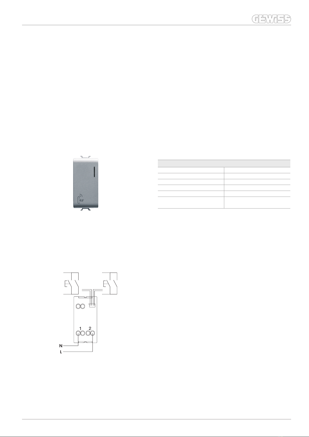
TECHNICAL DATA
Power supply 2 alkaline-type batteries (1.5V AAA)
Average battery life: 2 years
Operating temperature -5 to +40°C
Degree of protection IP20
Dimensions (LxHxD) ONE plates:
4 channels: 140 x 90 x 20mm
1-2-3 channels: 118 x 90 x 20mm
LUX plates:
4 channels: 145x95x20mm
1-2-3 channels: 123x95x20mm
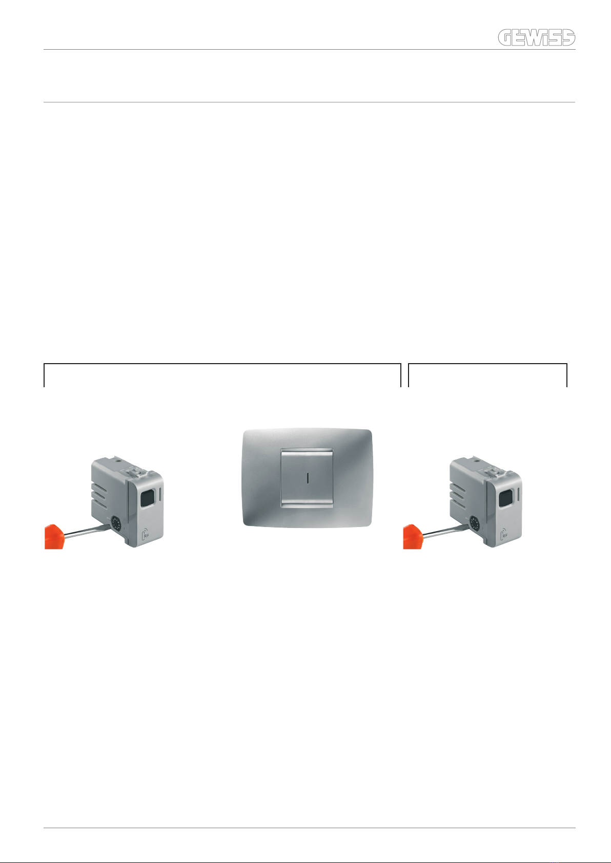
Wireless push-button panels
The push-button panel allows you to control lights, roller shutters, motors, etc. thanks the wireless communication with the output modules of the RF
Command and Control system.
The device is surface-mounting (with screws and wall plugs or double sided adhesive tape) or surface-mounting in 3-module flush-mounting boxes.
GW 10 801 - GW 10 802 - GW 10 803 - GW 10 804
GW 12 801 - GW 12 802 - GW 12 803 - GW 12 804
GW 14 801 - GW 14 802 - GW 14 803 - GW 14 804
ONE plate
GW 10 806 - GW 10 807 - GW 10 808 - GW 10 809
GW 12 806 - GW 12 807 - GW 12 808 - GW 12 809
GW 14 806 - GW 14 807 - GW 14 808 - GW 14 809
LUX plate
GW 20 963
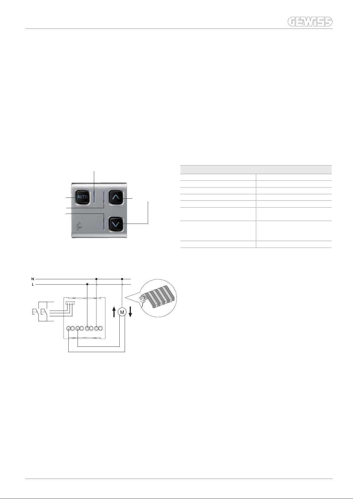
Wireless 3-channel remote control
The wireless remote control allows you to command lights, roller shutters, motors, etc. thanks to the wireless communication with the output modules of
the RF Command and Control system.
The device is portable. The pack includes a wall support.
The remote control has 6 implementation push-buttons (2 per channel).
TECHNICAL DATA
Power supply 2 alkaline-type batteries (1.5V AAA)
Average battery life: 2 years
Operating temperature -5 to +40°C
Degree of protection IP20
Dimensions (LxHxD) 120 x 45 x 20mm
Chorus RF
Technical Information Version 2.0
2
For technical information contact the Technical Assistance Service or visit gewiss.com

Wireless 2-channel input module
The 2-channel input module allows you to send 2 on/off or relay actuator adjustment commands of the RF Command and Control system, to control the
electrical load (lights, motors, roller shutters, doors, gates, awnings, etc.).
The mains-powered device reads the input signals coming from the potential free contacts of traditional equipment (push-buttons, switches, sensors, timers,
etc.) and sends commands using the built-in wireless transmitter.
The input signals are connected by two pairs of wires.
With the rotary selector the following function modes can be set:
- combined inputs mode (logic identical to push-button panel or RF remote control, with the two channels connected to the same RX receiver)
- status mode (periodical sending of input status)
- inversion mode (inversion of relay status)
- ALWAYS ON mode (sending of ON command only)
- ALWAYS OFF mode (sending of OFF command only)
Both channels follow the same operating logic in the STATE, INVERSION, ALWAYS ON and ALWAYS OFF operating mode (both channels operate in the same
mode) and can be associated to two different actuators.
TECHNICAL DATA
Power supply 230V AC
Operating temperature -5 to +40°C
Degree of protection IP20
Dimensions 1 CHORUS module
Section of supply cables max. 2.5mm2
Characteristics of input cables section 0.75mm2
length 200mm
Traditional command equipment inputs
(switches, push-buttons)
INPUT 2INPUT 1
GW 10 813 - GW 12 813 - GW 14 813
Connection diagram
Chorus RF
3
Technical Information Version 2.0
For technical information contact the Technical Assistance Service or visit gewiss.com

Wall-mounting wireless timed thermostat
The timed thermostat allows to automatically control, on a weekly basis, the temperature and timing inside the installation environment in combination with
the heating and air conditioning systems.
- Powered with 3 alkaline batteries (1.5V, type AAA)
- Programming on a weekly basis (a programme with hourly profiles independently configurable for each day of the week)
- Setting of hourly profile on 24-hour basis, with 3 different temperature levels (T1, T2, T3) and profile display
- Programming of times with a resolution of 15 minutes without a limit in the number of daily changes
- Residual current circuit breaker for adjustment can be set and differentiated for HEATING and AIR-CONDITIONING
- PARTY and HOLIDAY functions for programming special functioning speeds of different duration periods
- Functioning modes that can be set: AUTOMATIC / MANUAL / OFF
- Possibility to select the system thermal gradient self-learning function. This function optimises the anticipation of heating (up to 2 hours), in order to
guarantee the set temperature right from the programme start
- The device is installed on walls (with wall plugs or double-sided adhesive tape) or on the surface of 3-module flush-mounting boxes.
- The wireless timed thermostat must be combined with the actuator modules for general commands (GW 10 821 - GW 12 821 - GW 14 821 - GW 10 822 - GW 12
822 - GW 14 822).
LCD display
“UP”
push-button
“MODE” push-button
for selecting the
operation mode
“DOWN”
push-button
Configuration
push-buttons
GW 10 841 - GW 14 841
Base for fixing on wall with terminal block
Wiring terminals
Serial line: 4 - TX
5 - GND (common)
6 - RX
UP
TECHNICAL DATA
Power supply 3 alkaline-type batteries (1.5V AAA)
Average battery life: minimum 1 year
Dimensions 130 x 92 x 23mm
Operating temperature -5 to +45°C
Detected temperature display range 0 to +45°C
Adjustment range +5 to +40°C
Tolerance ± 0.5°C to 20°C
Chorus RF
Technical Information Version 2.0
4
For technical information contact the Technical Assistance Service or visit gewiss.com

Wireless IR movement detector with twilight sensor
The detector is battery powered and equipped with a presence sensor and a light-sensitive sensor whose threshold can be adjusted by a potentiometer.
The device allows the electrical loads to be activated and deactivated by the radio transmission of messages to the output modules present in the RF Command
and Control system.
The device has three freely configurable operating modes:
1) Movement sensor;
2) Movement and light sensitive sensor;
3) Light sensitive sensor.
This means that it can send differentiated messages to three groups of actuators; for example, the detector can be used at the same time as a movement sensor
to manage some RX output modules, and as a light sensitive and movement sensor to manage the others.
The device can be wall-mounted (fixed with plugs) or installed on a 3-module flush-mounting box.
TECHNICAL DATA
Power supply 3 alkaline-type batteries (1.5V AAA)
Average battery life: 2 years
Operating temperature -5 to +40°C
Degree of protection IP20
Dimensions (LxHxD) 118x90x20mm ONE plates
123x95x20mm LUX plates
Light sensitive threshold adjustment 5 - 1000 lux
Horizontal detec. angle 105°
Vertical detec. angle 52.5°
IR operating range 8m
ONE plate
GW 10 811 - GW 12 811 - GW 14 811
LUX plate
GW 10 816 - GW 12 816 - GW 14 816
Function selection
dip-switch
Accessible by removing
the plate
Light sensitive threshold adjustment
Association transmission
push-button
Green signalling
LED
COVERAGE DIAGRAM
Horizontal cover
Vertical cover
D
C
B
A
Chorus RF
5
Technical Information Version 2.0
For technical information contact the Technical Assistance Service or visit gewiss.com

Wireless output modules for general loads, 1-channel 3A and 16A - 250V
When combined with wireless transmitter devices (push-button panel, remote control, IR movement detector, 2-channel input module, timed thermostat) of
the RF Command and Control system, the output module receives commands and activates the electrical load by means of the relay output.
The implementations (selected with the rotary selector) are of the following types:
- Bistable (e.g. for normal light management);
- Timed (e.g. for stair light);
- Monostable (e.g. for doorbell).
The relay can also be activated by the local key or by an input (two-wire) made available for reading of contact without potential.
TECHNICAL DATA
Code GW 10 821 - GW 12 821 - GW 14 821 GW 10 822 - GW 12 822 - GW 14 822
Power supply 230V AC 230V AC
Operating temperature -5 to +40°C -5 to +40°C
Degree of protection IP20 IP20
Dimensions 1 Chorus module 2 Chorus modules
Section of supply cables max. 2.5mm2max. 2.5mm2
Characteristics of input cables section 0.75mm2section 0.75mm2
length 200mm length 200mm
Control elements 1 rotary selector, 1 local relay command button,
2 cables (potential-free input)
Type of output Contact with potential 230V AC Potential-free contact
Output contact 3A(AC1) / 2A(AC15) 250V AC 16A(AC1) / 10A(AC15) 250V AC
Type of load
- resistive loads
- incandescence lamps
- uncompensated fluorescent lamps unsuitable
- fluorescent lamps with electronic transformers unsuitable
- motors and motor reduction units
3A 16A
2A 10A
unsuitable 4A
unsuitable 4A
2A 10A
Control push-button
Not suitable for compensated fluorescent lamps and for discharge lamps; please use an auxiliary relay to control such lamps.
Multipurpose LED Control push-button Multipurpose LED
Conventional command
equipment input
(switches, push-buttons)
Conventional command
equipment input
(switches, push-buttons)
GW 10 821 - GW 12 821 - GW 14 821 GW 10 822 - GW 12 822 - GW 14 822
Connection diagram Connection diagram
4 3 2 1
N L
Chorus RF
Technical Information Version 2.0
6
For technical information contact the Technical Assistance Service or visit gewiss.com

Wireless output modules for roller shutters, 1-channel 8A - 250V
When combined with transmitter devices (push-button panel, remote control, 2-channel interface module) of the RF Command and Control system, the output
module receives commands and activates the relay for the activation of the roller shutters, awnings and similar.
The output module provides for three operating states:
- UP position (corresponding to lifting in the case of roller shutters, etc.);
- DOWN position (corresponding to lowering in the case of roller shutters, etc.);
- STOP position (no output fed).
There is an operation time limit during UP and DOWN status (settable by means of the rotary selector), after which the device always goes to STOP status with
neither output powered.
Via the wired input, it is possible to connect potential-free contacts with 2 conventional NO push-buttons, or a double push-button with interlock.
The motor command module is equipped with a three-colour (yellow/red/green) multipurpose LED to indicate the working mode, and a pair of front button keys
to command the output relays locally.
TECHNICAL DATA
Power supply 230V AC
Operating temperature -5 to +40°C
Degree of protection IP20
Dimensions 2 CHORUS modules
Section of supply cables max. 2.5mm2
Characteristics of input cables section 0.75mm2
length 200mm
Control elements 1 rotary selector
1 key for AUTO function
2 push-buttons for local relay control
Output contact 8A(AC1) / 3A(AC15) 250V AC
Local command button
keys
Auto button key
Multipurpose LED
Output status
LED
Conventional command
device input
(NO push-buttons)
Connection diagram
4 3 2 1
L N
GW 10 823 - GW 12 823 - GW 14 823
Chorus RF
7
Technical Information Version 2.0
For technical information contact the Technical Assistance Service or visit gewiss.com

Wireless signal repeater
The wireless repeater is use to resolve installation problems in which direct radio connections are not possible between the command device and an activation
device, due to excessive distance or obstacles (reinforced concrete structures, metal sheeting, etc.) that limit the transmission of the radio signal.
In this case the distance should be divided into shorted parts, or following a different course, placing a RF signal repeater capable of receiving the messages sent
by the command device and send them on to the activation device. The device can manage up to 16 different radio connections (paths with several repeaters
can be executed for covering long distances).
The signal repeater acts as a 1-channel actuator, as it contains a 16A relay. The relay inside the signal repeater can be controlled by up to 16 wireless input
command devices.
TECHNICAL DATA
Power supply 230V AC
Operating temperature -5 to +40°C
Degree of protection IP20
Dimensions 2 CHORUS modules
Section of supply cables max. 2.5mm2
Control elements 1 button key to send messages in the
learning phase
1 rotary selector
Reception distance 100m
Transmission distance 30m
No. of reception and transmission channels 16
Output contact 16A(AC1) / 10A(AC15) 250V AC
GW 10 831 - GW 12 831 - GW 14 831
Transmission button key
Multipurpose LED
1
2
4 3 2
N
1
L
N
L
N
L
3
4
230V - 50Hz
NO 16A - 250V AC
Connection diagram
Chorus RF
Technical Information Version 2.0
8
For technical information contact the Technical Assistance Service or visit gewiss.com
Table of contents
Other Gewiss Control System manuals
Popular Control System manuals by other brands

Truma
Truma MonoControl CS operating instructions

Mitsubishi Electric
Mitsubishi Electric MJ-310E Operation manual

inVENTer
inVENTer iV-Smart+ installation instructions

Siegenia
Siegenia DRIVE axxent DK Assembly and operating instructions

Ansul
Ansul AUTOPULSE IQ-396X Programming manual

Milltronics
Milltronics RH Series Instruction handbook