Gewiss Chorus GW 90797A User manual

KNX logic module - DIN rail mounting
GW 90797A
Technical Manual

2
Ge n e r a l
The KNX logic module can be programmed with this
application.
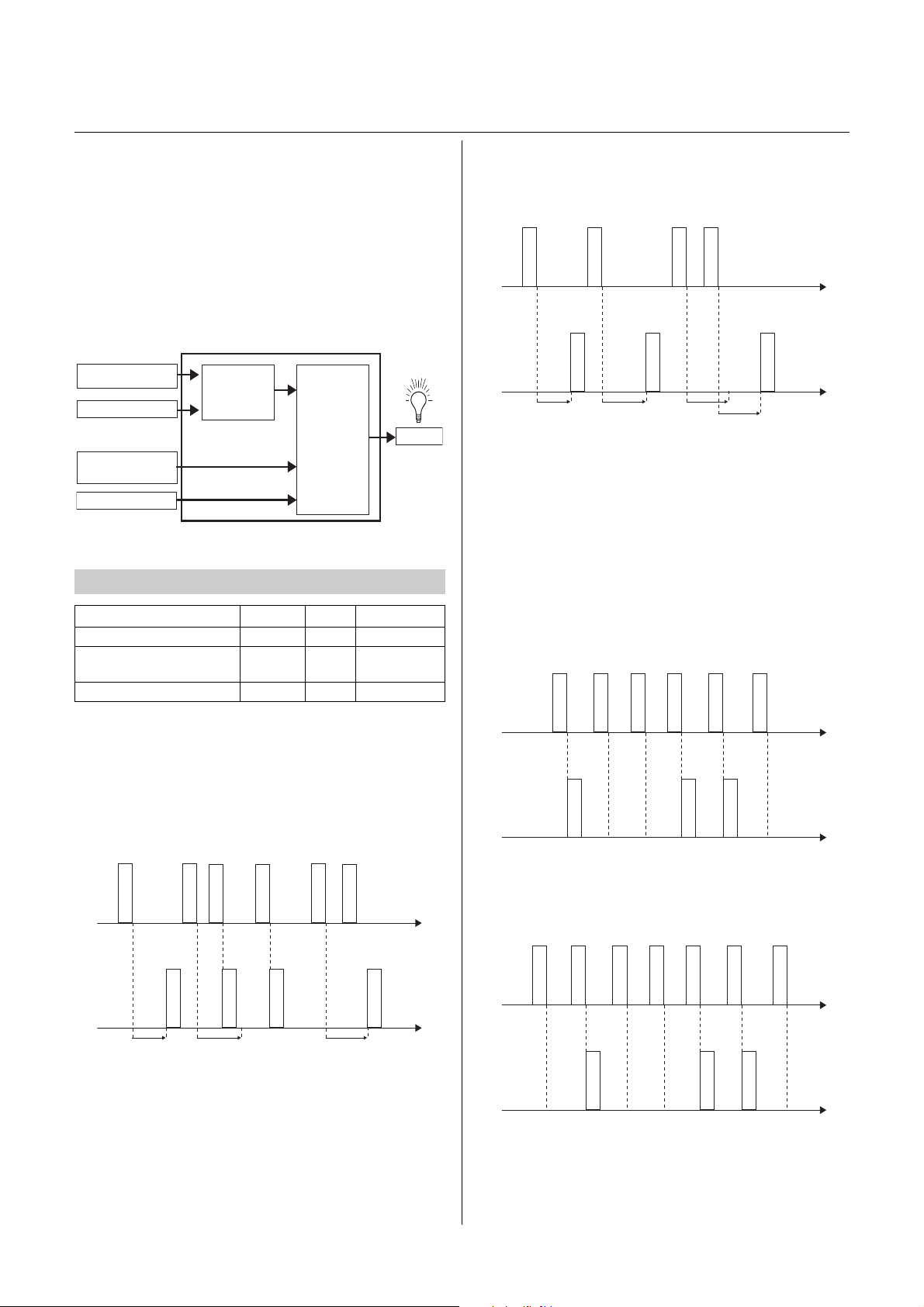
In complex KNX installations, the logic module serves
to establish special logic operations between sensors
and actuators.
The logic module is a DIN rail mounted device for in-
stalling distributors. The connection to the KNX is es-
tablished via the bus connecting terminal. An additional
supply voltage is not required.
This application offers a wide range of possible settings
for executing numerous logic functions for controlled
KNX devices (e.g. dimming or switch actuators etc). Of
course, which function is possible in each individual
case depends on the KNX devices being controlled. In
the following, only the KNX control functions and the
objects relevant to these and parameters of the logic
module are described. Due to the large number of pos-
sible settings, the logic module is particularly well suit-
ed to the areas of security, comfort or energy saving.
The logic module serves solely to utilise bus telegrams.
Only one application program is used for all settings.
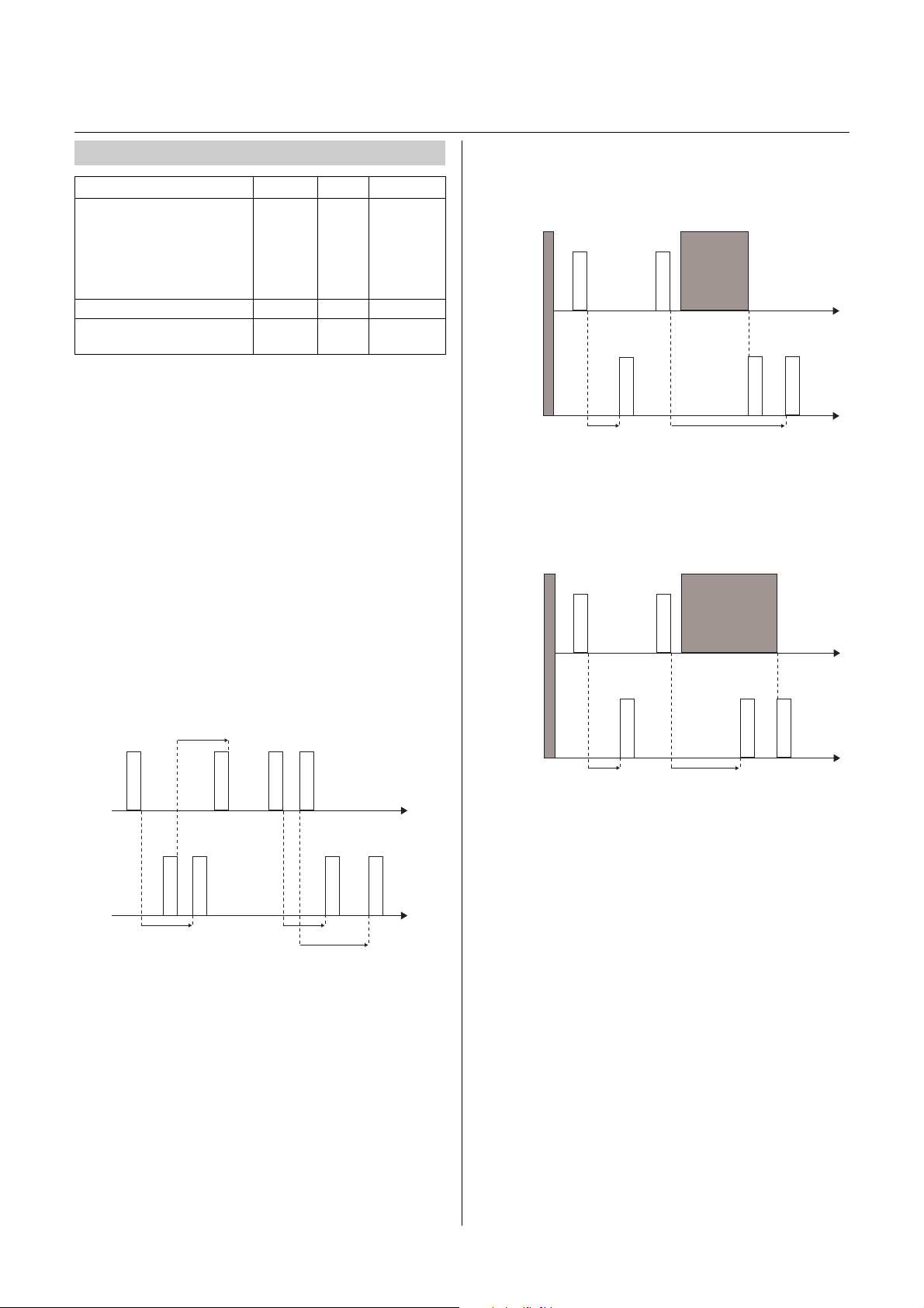
|Configurable times (staircase timer, ON delay,
OFF delay, etc.) are set via the time base and time
factor parameters. The actual time is calculated by
multiplying both values; e.g. base 1 second multi-
plied by factor 3 equals 3 seconds.
|If you load the logic module into your project via
the ETS, all functions (in the "General" tab) are de-
activated. Activate the function(s) you require.
Functions
If you load the logic module into your project via the
ETS, all functions (in the "General" tab) are deactivated.
Activate the function(s) you require.
The following functions can be selected:
– Total number of function objects: 202
– Global objects: 6
– Additional objects: for 3 push-buttons and 3 LEDs
– max. 230 objects
– max. 255 connections
|The setting examples shown in this application de-
scription serve merely as guidance and may devi-
ate from the settings actually required.
|The bold values are the values set during factory
configuration.
|The first block of a function is described in each
case, since all blocks have the same parameters
and setting values.
|Always set all parameters on the first block before
parameterising the next block.
Downloading the application deletes all data required
for the behaviour when the bus voltage is re-estab-
lished. All input values are set to "0". Even if the "Status
before bus voltage failure" setting is activated, the in-
puts are "0" after downloading. Likewise, the gate is al-
ways closed. This means that the settings for the
behaviour when bus voltage fails do not apply to the
download.
A few parameters that are relevant to all functions and
their settings, and consequently also their behaviour,
will be described first, before the individual functions of
the logic module are elaborated on.
These parameters are as follows:
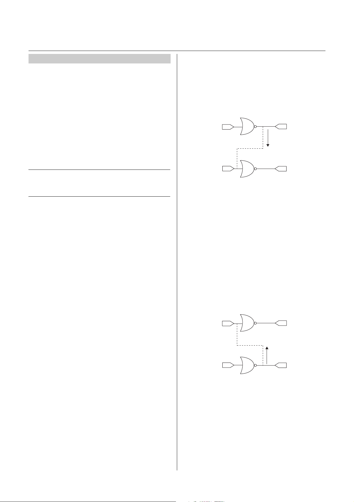
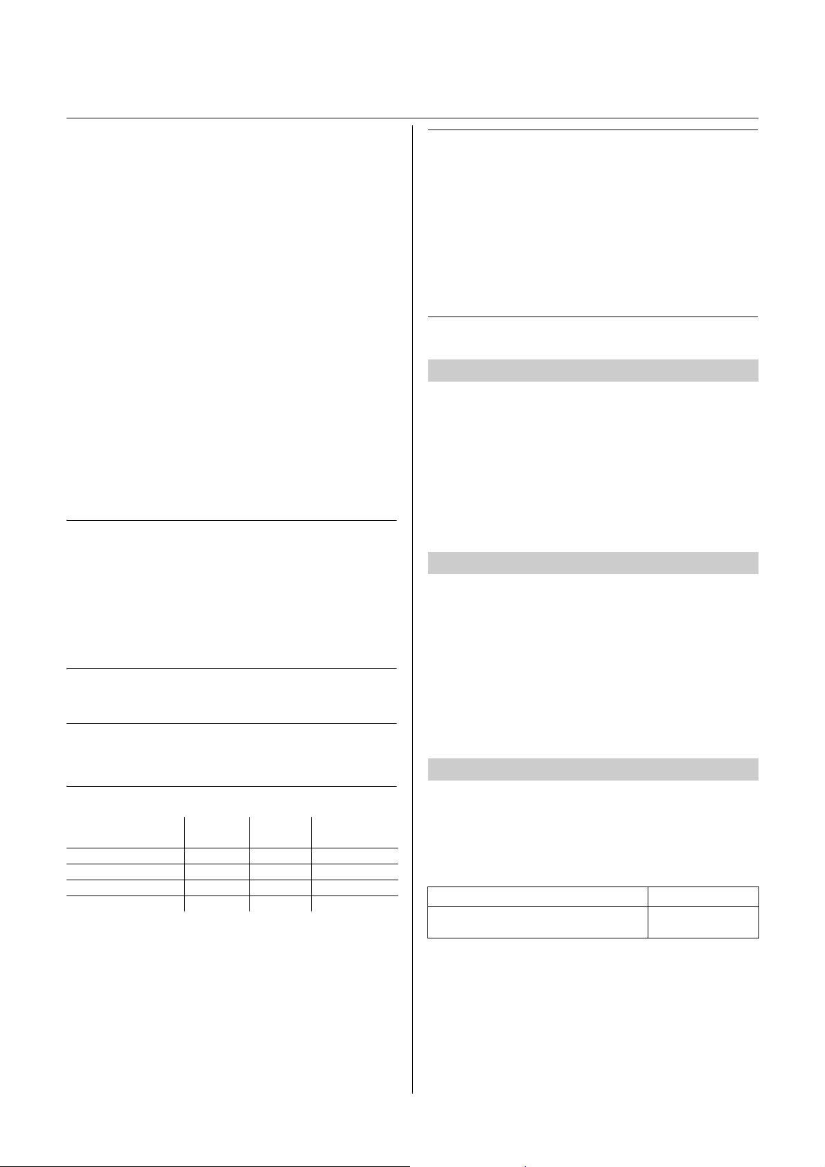
• Behaviour when bus voltage is re-established
•Gatefunction
• Internal connection
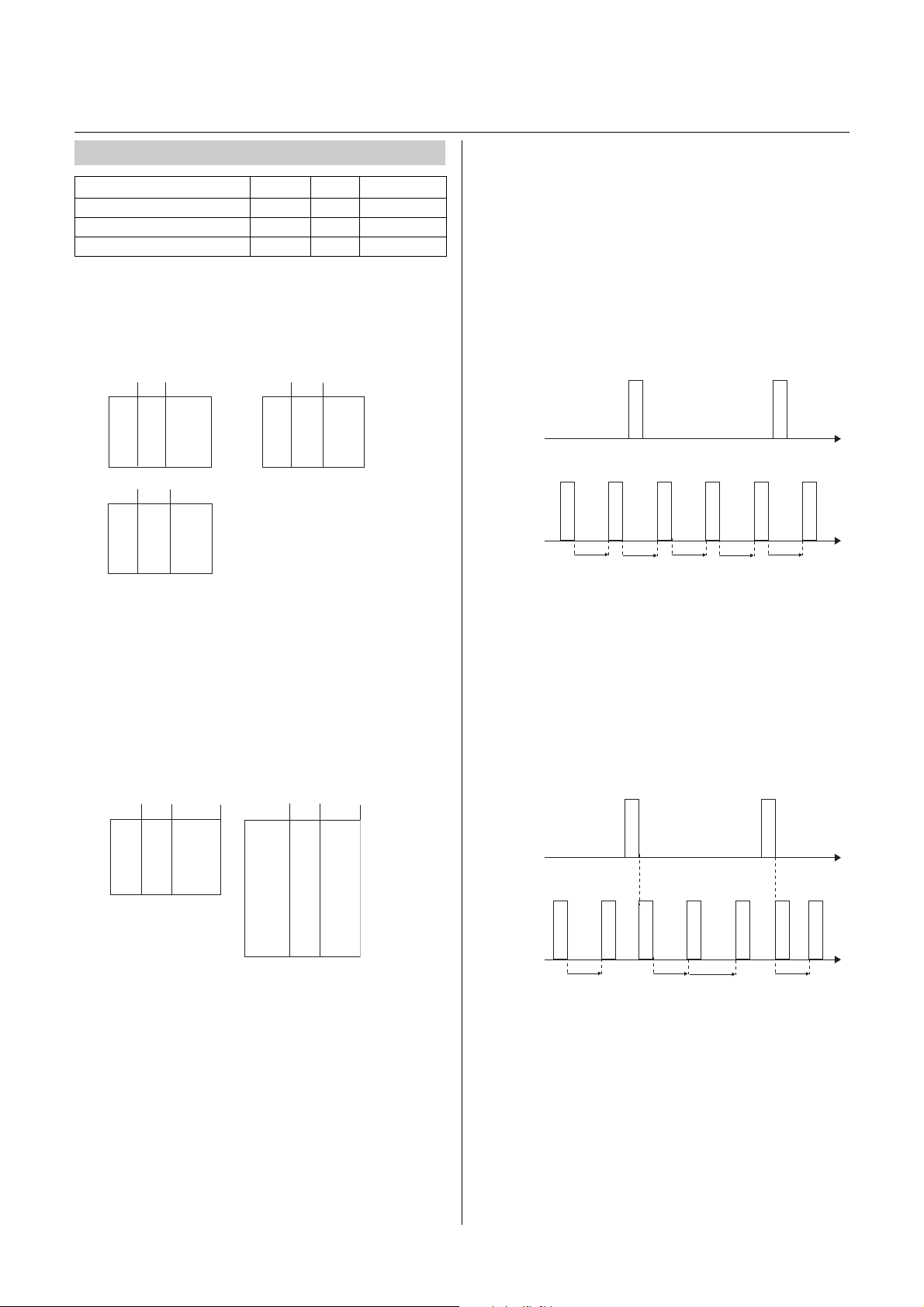
Start-up delay
Time delay between re-establishment of the bus volt-
age and the functional start of the logic module.
Set a time from which the reading of the input telegram
is successful.
Input objects
General input objects: Logic object, time delay and filter
object, converter object and multiplexer object.
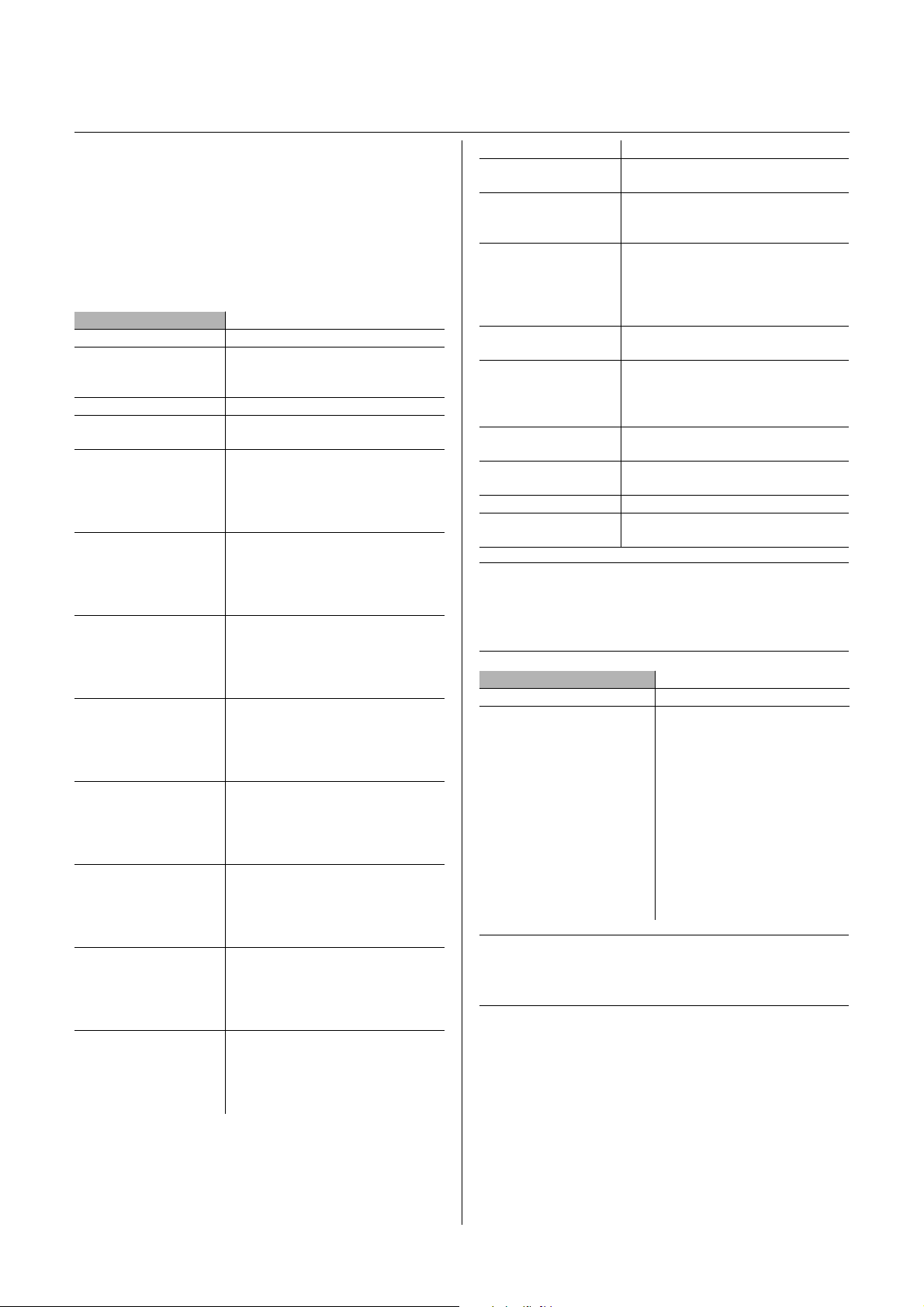
Function Number of
blocks
Number of
objects
Number of
function objects
Logic 10 10 100
Time delay and filter 10 3 30
Converter 8 3 24
Multiplexer 12 4 48
Behaviour after ETS application download
Ge n e r a l p a r a m e t e r s
Behaviour when bus voltage is re-established
Parameter name Objects
Start-up delay after re-establishment of
the bus voltage in s 1 ... 120, 25

3
Input behaviour
The behaviour of the input after re-establishment of the
bus voltage can be determined here.
Reads the current value: A status inquiry is sent to the
bus and the response is awaited. The inquiry is repeat-
ed every minute until the first telegram arrives at the in-
put. For this setting, it is essential that the read flag
(R-flag) is set for the corresponding sensor or actuator.
During commissioning (perform reset), check that the
read operation was completed successfully and that re-
reading every minute following successful receipt was
set.
|An unnecessary burden is placed on the bus if the
L flag is not set (too many cyclical telegrams) and
the other bus functions are impaired to too great
an extent.
Waiting for new telegram: No inquiry is sent to the bus.
The input waits for the first new telegram.
Status before bus voltage failure: All inputs are replaced
with the values stored in the memory after the bus volt-
age is re-established.
0 until first telegram: The value of the input object is "0"
until another telegram (apart from 0telegrams) is re-
ceived.
1 until first telegram: The value of the input object is "1"
until another telegram (apart from 1telegrams) is re-
ceived.
All function blocks listed above include a gate function
at the output with which the output behaviour can be ad-
justed.
The gate and its adjustable parameters are the same for
all functions of the logic module that can be selected in
the ETS.
Input behaviour
The gate is either open (all telegrams are let through) or
closed (no telegram is let through). The behaviour can
be inverted.
Ga t e b e h a v i o u r
The gate has either the value 1 or 0. The behaviour can
also be inverted.
Output behaviour
The user can select whether the gate sends a telegram
upon opening or not and whether the value of the output
is inverted.
Example 1:
The gate closes and the last incoming telegram is
saved. The gate is opened again and the saved tele-
gram is forwarded.
Example 2:
Setting: The gate closes, no telegram is saved. The
gate is opened again and the first incoming telegram is
forwarded.
Example 3:
Setting: The gate closes, the last telegram is saved.
The status of the output is inverted. The gate is opened
again and the saved telegram is forwarded with inverted
value (1 -> 0).
Gate function
Gate opened Gate closed Gate opened
Input
telegram
Output
telegram
10
10
10 10
100
Gate opened Gate closed Gate opened
Input
telegram
Output
telegram
10
10
10 10
10
Gate opened Gate closed Gate opened
Input
telegram
Output
telegram
10
01
11
1
0
00

4
The internal connection function serves to reduce the
number of group addresses and telegrams, thereby
considerably reducing the bus load.
The internal connection can be activated for the logic
function, the time delay and filter function, as well as for
the converter function. The adjustable connections are
always the same. The logic module only ever supports
the additional "internal connection" function for the first
input of a function block. Other functions are supported
via a virtual input, which can be selected freely.
Special effects are achieved by combining internal con-
nections and group addresses (e.g. complex logic con-
nections or block connections without group address).
|Double assignment (internal and with a group ad-
dress) should only be implemented in justified ex-
ceptional cases.
The modules are worked through in the following order:
• Logic function
• Time delay and filter function
• Converter function
• Multiplexer function
Furthermore, the blocks of each function are worked
through one after the other (first logic block 1, then logic
block 2 through to logic block 10. Subsequently, time
delay and filter block 1, etc.).
If an input is connected to both an internal connection
and also to a group address, the result at the output de-
pends on whether the internal connection comes from
a "higher" or "lower" block.
Examples
• Below is described how a logical AND operation can
be established between two internal connections.
Example 1: Block 1 and block 2 invert the input values
in each case. The output from block 1 is internally con-
nected to the input from block 2.
Block 1 and 2 are updated simultaneously. First, block
1 is recalculated, which then alters the input for block 2.
Block 2 now has a new input value. Both steps are com-
pleted in one cycle.
The input telegram (2/0) has the value 0. The output tel-
egrams have the values 1 (2/11) and 0 (2/21). This
means that the input value "0" is overwritten with a "1"
by the internal connection at the input to block 2.
Example 2: Block 1 and block 2 invert the input values
in each case. The output from block 2 is internally con-
nected to the input from block 1.
Block 1 and 2 are updated simultaneously. First, block
1 is recalculated. In the next stage, block 2 is calculat-
ed. The result from block 2 updates the input to block 1.
In the next cycle, the value of block 1 is recalculated.
The output value for the group address 1/11 was altered
twice. The time delay between the two results depends
on the number of blocks used.
Internal connection
--- Internal output connection
OR
OR
2/0
2/0
2/11
2/21
Logik-
block 1
Logik-
block 2
Logic block 1
Logic block 2
OR
OR
1/0
1/0
1/11
1/21
Logik-
block 1
Logik-
block 2
Logic block 1
Logic block 2

5
Logic operation
There are a total of 10 logic blocks available.
You can choose from one of the following logic gates for
each logic block: AND / OR / EXCLUSIVE OR (XOR).
All gates can be inverted.
The difference between the "or" and "exclusive or" logic
operations is that the output from the XOR gate is logi-
cal "1" if and only if there is an unequal number of "1"
and "0" inputs. In the simple case of an XOR gate with
two inputs, this means that the inputs must be different
to one another to obtain the output "1". "1" must be pre-
sent at precisely one of the two inputs.
In contrast to a simple OR logic operation, the condition
is deemed not to be met if a "1" is present at both inputs.
With an XOR gate, the result in this case is a "0". Each
additional input at the gate alters the behaviour accord-
ingly.
Input behaviour
The input telegrams can be inverted for each input. In
addition, a fixed value (0 or 1) can be assigned.
Output behaviour
Criteria for the sending behaviour at the output can be
defined.
Output change: A telegram will only be sent if the result
of the logic operation alters. This means that cyclical in-
put telegrams at the output do not trigger cyclical tele-
grams.
Receipt of an input telegram: An output telegram will be
sent after receipt of an input telegram, regardless of the
logic result. This means that cyclical input telegrams
also trigger cyclical output telegrams (same cyclic inter-
val).
Cyclically: An output telegram will be sent exclusively at
the set cyclic intervals. This cyclic interval consists of a
selectable basis (1 s or 1 min) and an additional adjust-
able factor (1...65535). This means that non-cyclical in-
put telegrams are also converted into cyclical output
telegrams.
Cyclically and output change: In addition to the cyclical
sending, output telegrams will also be sent in the case
of changes at the input. The send conditions for output
telegrams outside the cyclic interval result from the def-
inition of send criteria (output change or receipt of a tel-
egram). This setting is wise if cyclical telegrams and a
rapid response are expected (e.g. weather alarm at the
blind actuator).
Logic function
Object name Size Flag Direction
Logic object 1...8 1 bit CW Input
Logic gate input control 1 bit CW Input
Logic output 1 bit CT Output
A B OR NOR
0 0 0 1
0 1 1 0
1 0 1 0
1 1 1 0
A B AND NAND
0 0 0 1
0 1 0 1
1 0 0 1
1 1 1 0
A B XOR XNOR
0 0 0 1
0 1 1 0
1 0 1 0
1 1 0 1
A B OR XOR
0 0 0 0
0 1 1 1
1 0 1 1
1 1 1 0
A B C OR XOR
0 0 0 0 0
0 0 1 1 1
0 1 0 1 1
0 1 1 1 1
1 0 0 1 1
1 0 1 1 1
1 1 0 1 1
1 1 1 1 0
t Cyclic interval
t Cyclic interval
Input
Output 11
0
00
1
1
0
ttttt
Input
Output 11
0
00
1
1
0
tttt
1

6
Basic applications
The logic function is particularly suitable for summaris-
ing messages (e.g. the lighting status in rooms), linking
conditions (e.g. rain or wind sensor activates a safety
function) or programming an additional toggle between
manual and automatic (e.g. disabling brightness-de-
pendent lighting control for a video presentation).
Parameter
|The value of logic object 1 is either "use" or "invert-
ed". It is not possible to set a fixed value or "do not
use". The value of logic object 2...8 can be "do not
use", "use", "inverted", =0 or =1.
|Never connect the output and the input of the
same logic blockto one another, as this can cause
the device to malfunction.
Logic block 1
Parameter Setting
Logic gate AND
OR
EXCLUSIVE OR
Logical inputs
Value of logic
object 1
Use
inverted
Behaviour of logic object
1 when bus voltage
re-established
Reads current value
Waits for new telegram
Status before bus voltage failure until
first telegram
1 until first telegram
Value of logic
object 2
Do not use
use
inverted
=1
=0
Value of logic
object 3
Do not use
use
inverted
=1
=0
Value of logic
object 4
Do not use
use
inverted
=1
=0
Value of logic
object 5
Do not use
use
inverted
=1
=0
Value of logic
object 6
Do not use
use
inverted
=1
=0
Value of logic
object 7
Do not use
use
inverted
=1
=0
Value of logic
object 8
Do not use
use
inverted
=1
=0
Parameter Setting
Gate function 1= closed, 0= opened
0 = closed, 1 = opened (inverted)
Send output telegram if
gate opens Yes
No
Behaviour of gate when
bus voltage re-estab-
lished
Reads current value
Waits for new telegram
Status before bus voltage failure
Opened
Closed
Value of
output objects
uses
inverted
Send result After output change
After receiving an input telegram
Cyclically
Cyclically and after output change
Cyclic interval =
basis x factor
Basis 1 s
1 min
Factor 1 ... 65535, 10
Internal connection Ye s
No
Internal connection
Parameter Setting
Output of basic logic function
logic block 1 is connected to
Nothing
Logic block 1 logic object 1 ...
Logic block 10 logic object 1
Time and filter block 1 ...
Time and filter block 10
Converter block 1 ...
Converter block 8
Signal 1
Signal 2
Signal 3

7
Application example
• A light-sensitive switch switches the lighting on auto-
matically.
• The light is switched off between 23:00 and 06:00.
• In the morning, the light switches on from 06:00 when
it is dark.
• In addition, the light can be switched on for 5 minutes
at any time via a push-button.
• A continuous light function is possible for mainte-
nance purposes.
Time delay
Output telegrams can be sent with a time delay. Switch-
on and/or switch-off times can be adjusted depending
on the input telegram. The time delay can also be deac-
tivated.
Example: Time delay if 1. The 1telegram is forwarded
with a time delay. The 0telegram cancels the time delay.
Example: Time delay if 0 and 1. Both telegrams are for-
warded with a time delay.
Filter function
Ten different assignments of input and output telegrams
are available. It is possible to switch ON or OFF or to
TOGGLE, to send only certain telegrams (e.g.
ON-> ON, OFF -> - ) or to invert the input value.
Example 1: 1 -> 1 / 0 -> -. 1telegrams are let through
and 0telegrams are filtered out.
Example 2: 1 -> - / 0 -> 1. 1telegrams are filtered out and
0telegrams are converted into 1telegrams.
Time delay and filter function
Object name Size Flag Direction
Time delay and filter object 1 bit CW Input
Gate input control
filter
1 bit CW Input
Time delay and filter output 1 bit CT Output
t = delay time
Logic
operation 1
AND
OR
Time switch
Twilight sensor
Maintenance light
Push-button with
time function
Switch
Logic
operation 2
1
0
0
1
1
1
1
tt
1
t
0
0
t = delay time
0
10
1
tt
1
t
0
0
t
Time delay
if 0 and 1
1
1
0001
1
1
1
Filter
1 -> 1 / 0 -> -
0
1
1110
1
0
1
Filter
1 -> - / 0 -> 1
1

8
Example 3: 1 -> toggle / 0 -> -. 0telegrams are filtered
out. The 1telegrams toggle between 0 and 1.
10 blocks are available for time delay and filter func-
tions. All blocks are deactivated and must be activated
individually and functions must be assigned to them.
Basic applications
The time delay function and filter are particularly suita-
ble for sending messages with a time delay (e.g. dark-
ening the building after closing the windows or comfort
extension), adapting signals (e.g. key is not able to sup-
press 1, 1 is filtered out). Alternatively, toggling between
manual and automatic can be programmed.
Parameter
|Never connect the output and the input of the
same block to one another (internal connection or
group addresses), as this can cause the device to
malfunction.
0
1
1110
1
0
Filter
1 -> toggle / 0 -> 1
0
Time delay and filter func-
tion
Parameter Setting
Time delay No
if 1
if 0
if 0 and 1
Filter 1 -> 1 / /0 -> -
1 -> - / 0 -> 0
1 -> 1 / 0 -> 0
1 -> - / 0 -> - (switched off)
1 -> - / 0 -> 1
1 -> 0 / 0 -> -
1 -> 0 / 0 -> 1
1 -> toggle/ 0 -> -
1 -> - / 0 -> toggle
1 -> toggle
0 -> toggle
Status of the time and fil-
ter object after bus volt-
age re-established
Reads current value
Waits for a new telegram
Status before bus voltage failure
0 until first telegram
1 until first telegram
Gate function 1= closed, 0 = open
0 = closed, 1 = open (inverted)
Send output telegram if
gate opens Yes
No
Behaviour of gate when
bus voltage re-estab-
lished
Reads current value
Waits for new telegram
Status before bus voltage failure
opened
closed
Send result After output change
After receiving an input telegram
Cyclically
Cyclically and after output change
Use internal connection Yes
No
Internal connection
Parameter Setting
Time delay output and block 1
filter function is connected to
Nothing
Logic block 1 logic object 1 ...
Logic block 10 logic object 1
Time and filter block 1 ...
Time and filter block 10
Converter block 1 ...
Converter block 8
Signal 1
Signal 2
Signal 3

9
1 bit signals can be converted into 2 bit or into 1 byte
signals and 1 byte signals can be converted into 1 bit
signals using the converter function.
There are 8 converter blocks available. All blocks are
deactivated and must be activated individually and
functions must be assigned to them. The transition from
"0" to "1" can be adjusted.
Basic applications
1 bit -> 2 bit conversion: Switching with priority, e.g. load
management.
1 bit -> 1 byte conversion: Limit value with 1 bit is used
to retrieve a lightscene.
1 byte -> 1 bit conversion: 1 byte value generates 1 bit
status feedback for an LED.
Parameter
|Never connect the output and the input of the
same block to one another (internal connection or
group addresses), as this can cause the device to
malfunction.
Example 1 bit -> 2 bit
• A room is controlled via KNX.
• In the event of fire, 1/3 of the complete lighting should
be switched on.
• The selected priority control ensures that this target is
achieved.
Example 1 byte -> 1 bit
• The heating control is monitored by a visualisation.
• An LED display appears in the visualisation when the
valve position is exceeded by x%.
• Monitoring of room temperature and central reduction
of the setpoint temperature of the heater, where nec-
essary.
Converter function
Object name Size Flag Direction
Converter input/
output object
1 bit
2 bit
1 byte
CW
CT
CT
Input
Output
Output
Converter
gate input control
1 bit CW Input
Converter block 1
Parameter Setting
Converter function 1 bit -> 2 bit /
1 bit <-> 1 byte
Value for 0telegrams 0... 255
Value for 1telegrams 0 ... 255
0telegram is generated if 1
byte value is < ... 0...255, 1
Status of the converter af-
ter re-establishment of the
bus voltage
Reads current value
Waits for new telegram
Status before bus voltage failure
0 until first telegram
1 until first telegram
Send output telegram if
gate opens Yes
No
Send result After output change
After receiving an input telegram
Cyclically
Cyclically and after output change
Use internal connection Yes
No
Internal connection
Parameter Setting
Output converter function block
1 is connected to
Nothing
Logic block 1 logic object 1 ...
Logic block 10 logic object 1
Time and filter block 1 ...
Time and filter block 10
Converter block 1 ...
Converter block 8
Signal 1
Signal 2
Signal 3

10
The gate integrated into the multiplexer serves to con-
trol the flow of data.
The following formats can be selected:
–1bit
–2bit
–4bit
–1byte
–2byte
– 4 byte (only in the first multiplexer block)
The multiplexer is bidirectional and the data direction
can be altered via the control object.
There are 12 multiplexer blocks available. All blocks are
deactivated and must be activated individually and
functions must be assigned to them.
The time delay is set separately for each individual mul-
tiplexer block. The time delay can be retriggered after a
new update is received.
Output behaviour
Send output telegram if gate opens: An output telegram
is sent after the gate status changes (gate is opened).
This only happens once the delay time has elapsed,
however. The telegram is not sent immediately after the
gate opens, but instead only once the delay time has
elapsed. If the delay time has already elapsed before
the gate opens, however, the telegram will be sent im-
mediately when the gate is opened.
Example 1: The gate is closed and the delay time is ac-
tive. The gate is open and the time has not yet elapsed.
An output telegram will be sent when the delay time has
elapsed.
Example 2: The gate is closed and the delay time is ac-
tive. The time has elapsed and the gate is still closed. If
the gate is opened, an output telegram will be sent im-
mediately.
Basic applications
The multiplexer is particularly suitable for controlling
conference rooms (e.g. a large conference room can be
divided into several small rooms using moveable walls.
Push-button signals are then only forwarded to the re-
spective sections).
Multiplexer function
Object name Size Flag Direction
Multiplexer
Input /
output object A, B
1 bit
2 bit
4 bit
1 byte
2 byte
4 byte
CWT Input / out-
put
Control object 1 bit CW Input
Multiplexer
gate input control
1 bit CW Input
t = time delay (adjustable)
1
0
0
1
1
1
1
1
tt
t
t
XX
t = delay time
t = delay time
Object A 0
0
Object B
X
A -> B
t
0
1
1
t
Gate
closed
Object A 0
0
Object B
X
A -> B
t
0
1
1
t
Gate
closed

11
Parameter
|Do not connect the output from multiplexer block 1
to multiplexer block 1, as this can cause the device
to malfunction.
Control object
Control object A -> B specifies the direction and the val-
ue telegram is delayed.
Example 1: The multiplexer deletes the previous tele-
gram following the change of direction to B -> A, since
Bis the input object this time.
Example 2: The previous telegram is sent to the bus fol-
lowing the change of direction to A <-> B. Both objects
are the input and the output simultaneously.
Example 3: The previous telegram is deleted following
the change of direction to B / A, as the multiplexer block
is deactivated.
Multiplexer block 1
Parameter Setting
Type of multiplexer object 1 bit
2 bit
4 bit
1 byte
2 byte
4 byte
Control object = "0" A / B
A -> B
A <- B
A <-> B
Control object = "1" A / B
A -> B
A <- B
A <-> B
Ga t e f u n c t i o n 1= closed, 0 = opened
0 = closed, 1 = opened (inverted)
Send output telegram if gate
opens
Ye s
No
Behaviour of gate when bus
voltage re-established
Reads current value
Waits for a new telegram Status
before bus voltage failure
0 until first telegram
1 until first telegram
Send result After output change
After receiving an input telegram
Cyclically
Cyclically and after output change
Factor: Output telegram delay
(basis = 10 ms; 0 = no delay) 0.. 65535
Internal connection
Parameter Setting
Output multiplexer function
block 1 is connected to
Nothing
Logic block 1 logic object 1 ...
Logic block 10 logic object 1
Time and filter block 1 ...
Time and filter block 10
Converter block 1 ...
Converter block 8
Signal 1
Signal 2
Signal 3
t = delay time
t = delay time
t = delay time
Objekt A 0
0
Objekt B
B -> A
X
A -> B
t
1
1
t
1
1
t
Object A
Object B
Objekt A 00
Objekt B
A -> B
t
1
1
t
1
1
t
A <-> B
0
0
t
Object A
Object B
Objekt A 0
0
Objekt B X
A -> B
t
1
1
t
1
1
t
A / B
X
Object A
Object B

12
Each individual push-button and each individual LED
can be assigned its own function. These possibilities
are particularly suitable for testing (e.g. sending input
telegrams to a logic object at the push of a button) or
checking (e.g. LED lights up when logic function is acti-
vated) logic functions. Furthermore, push-buttons and
LEDs connected to the push-button input objects can
temporarily switch off connected logic operations.
|The minimum switching time factor is the minimum
time that a key must be pressed to send a switch-
ing signal to the bus.
This product must be installed, connected and used in
compliance with prevailing standards and/or installation
regulations. As standards, specifications and designs
develop from time to time, always ask for confirmation
of the information given in this publication.
Channel LEDs and channel push-buttons
Parameter Size Flags Direction
LED 1, LED 2, LED 3 1 bit CW Input
Push-button 1, push-button 2,
push-button 3
1 bit CT Output
Channel push-buttons and channel
LEDs
Parameter Setting
Behaviour of LED 1 after receiving the
signal 1 = 1/0
ON / OFF
OFF / ON
Flash / OFF
OFF / Flash
Flash / ON
ON / Flash
always off
Status of push-button object 1 after
push-button 1 was pressed
Toggle / -
1 / 0
0 / 1
1 / -
0 / -
Deactivated
Use internal
connection Yes / No
Behaviour of LED 2 after receiving the
signal 2 = 1/0
ON / OFF
OFF / ON
Flash / OFF
OFF / Flash
Flash / ON
ON / Flash
always off
Status of push-button object 2 after
push-button 2 was pressed
Toggle / -
1 / 0
0 / 1
1 / -
0 / -
Deactivated
Use internal
connection Yes / No
Behaviour of LED 3 after receiving the
signal 3 = 1/0
ON / OFF
OFF / ON
Flash / OFF
OFF / Flash
Flash / ON
ON / Flash
always off
Status of push-button object 3 after
push-button 3 was pressed
Toggle / -
1 / 0
0 / 1
1 / -
0 / -
Deactivated
Use internal connection Yes
No
Minimum switching time factor
(basis = 0.5 s) 1 ... 255
+39 035 946 111
8.30 - 12.30 / 14.00 - 18.00
lunedì ÷ venerdì - monday ÷ friday
www.gewiss.com
24h
GEWISS - MATERIALE ELETTRICO
Table of contents
Other Gewiss Control Unit manuals

Gewiss
Gewiss Chorus GW 10 361 User manual

Gewiss
Gewiss Chorus GW 10 754 User manual

Gewiss
Gewiss Chorus GW1 783A Series User manual

Gewiss
Gewiss CHORUSMART GWA1291 User manual

Gewiss
Gewiss CHORUSMART GW10677 User manual

Gewiss
Gewiss MSX/M 250c User manual

Gewiss
Gewiss Chorus GW 10 741 User manual

Gewiss
Gewiss Chorus GW 10 755 User manual

Gewiss
Gewiss CHORUS GW A9 471 User manual
Popular Control Unit manuals by other brands

Waves
Waves MDMX Screamer user guide

Eureka
Eureka Ruby Operation & installation instructions

National Instruments
National Instruments NI 9381 Getting started guide

Emerson
Emerson RSTi-OM user manual

Emerson
Emerson Keystone Figure 221 Series Installation and maintenance instructions

ST
ST UM0993 user manual