Gewiss CHORUS GW 90 872A User manual

Gateway KNX/DALI 64/16 - for guideDIN
GW 90 872A
Technical Manual

Page 1 of 45
Content
1. Using the application program……………………………………………………....................………………. 3
2. General product information..................................................................................................................... 3
2.1 DALI Bus system properties..................................................................................................... 3
2.2 GW90872A product features…..........................................................................................
3
3.
General properties of the ETS application program: GW90872A Plug-In…….............……………………
4
3.1 Installing the Plug-In…………………………………………………………………...…………….... 4
3.2 Principal structure of the Plug-In………………………………………………………...………… 4
3.3 Operating modes of the Plug-In: DALI commissioning…………………………………………. 5
4. DALI commissioning……………………………………………………………………………………………… 6
4.1 Commissioning with GW90872A via web site or pushbuttons.....................................
6
4.2 Commissioning with GW90872A via ETS Plug-In………………………………………….
6
5. Display and push-button control............................................................................................................ 7
6. Control via web browser……………………………………………………..………………………………….. 10
6.1 Configuration buttons………………………………..…………………………………….............. 11
6.2 Control buttons………………………………………………………………………………………. 12
6.3 ECG fields……………………………………………………………………..………………………. 13
6.4 Group fields..........………………………………………………………………………................... 13
6.5 Information and status fields........................………………………..…………………………… 13
7. ETS Special and commissioning functions…...……………………………………………………………… 16
7.1 Special functions in ‘Normal Mode‘………………………………………………………………… 16
7.1.1 Synchronisation with the connected DALI segment…...........…………………….. 16
7.1.2 User-friendly names for ECGs and groups..................……………………………… 17
7.2 Special functions in ‘Extended Mode‘ …………………………………………………………….. 17
7.2.1 Preparation and planning the DALI commissioning in ‘Extended Mode‘ .....….. 18
7.2.2 DALI commissioning in ‘Extended Mode‘ ……………………………………………. 19
7.2.3 ECG and lamp faults during DALI commissioning in ‘Extended Mode‘ 20
7.2.4 Using dummy ECGs in ‘Extended Mode‘.………................………………………… 21
7.3 General extra functions in the ETS ..……………………………………………………………….. 21
7.3.1 Using IP for plug-in communication.................…………………………………….... 21
7.3.2 Parameter templates……………………………………………………………………… 22
7.3.3 DALI configuration data back-up ………………………………………………………. 22
8. DALI maintenance and expansion…………………………………….………………………………………… 23
8.1. Quick exchange of individual ECGs…....………………………………….………………………. 23
8.2 Extending the existing system – post-installation...........………………………………………. 23
9. Different operating modes…………………………………………………………………………………………. 24
9.1 Normal mode…………………………………………………………………………………………..… 24
9.2 Permanent mode……………………………………………………………………………………….. 24
9.3 Staircase mode………………………………………………………………………………………… 24
9.4 Night-time mode………………………………………………………………………………………… 24
9.5 Panic / emergency mode……………………………………………………………………………… 24
9.6 Test mode for central battery emergency luminaires …………………………………………… 24

Page 2 of 45
9.7 Burn-in mode …………………………………………………………………………………………..…. 24
9.8 Operating mode hierarchy ……………………………………………………………………………… 25
10. Analysis and service functions …………………………………………………………………………………. 26
10.1 Recording operating hours ………………………………………………………………………….. 26
10.2 Individual fault recognition at ECG level ………………………………………………………….. 26
10.3 Fault analysis at group level ……………………………………………………………………....... 26
10.4 Fault analysis at device level ………………………………………………………………………... 27
11. Scenes and effects …………………………………………………………………………………………………. 27
11.1 The scene module ……………………………………………………………………………………… 27
11.1.1 Scene programming via the scene website…....……………………………………... 28
11.1.2 Scene programming via ETS in ‘Extended Mode‘……………………..........……… 28
11.2 The effect module………………………………………………………………………………………. 29
11.2.1 Effect programming using the effect website…...…………………………………… 29
11.2.2 Effect programming via ETS in ‘Extended Mode‘…........…………………………… 30
12. Self-contained battery emergency lamps ……………………………………………………………………… 31
12.1 Features ...............................................……………………………………………………………... 31
12.2 Converter inhibit mode ....................………………………………………………………………… 31
12.3 Test mode..........................................………………………………………………………………… 31
13. ETS communication objects overview ......………………………………………………………………….…. 32
13.1 General communication objects …………………………………………………………………….. 32
13.2 ECG-related communication objects ………………………………………………………………. 35
13.3 Group-related communication objects …………………………………………………………….. 36
14. ETS parameter overview .....…………………………………………………………………………………....…. 37
14.1 Device: General settings..…………………………………………………………………………….. 37
14.1.1 Parameter page: General Settings……………………………………………………… 37
14.1.2 Parameter page: IP Settings ……………………………………………………………. 38
14.1.3 Parameter page: Behaviour …………………………………………………………..…. 38
14.1.4 Parameter page: Special Functions …………………………………………………… 39
14.1.5 Parameter page: Analysis and Service ……………………………………………….. 39
14.2 ECG No. xx……………………………………………………………………………………..………… 40
14.2.1 Parameter page ECG No. xx……………………………………………………………… 40
14.2.2 Parameter page: Emergency Settings ……………………………………………........ 41
14.2.3 Parameter page: Switching Behaviour ……………………………………………….. 41
14.2.4 Parameter page: Analysis and Service ………………………………………………… 42
14.3 Group No. xx ……………………………………………..……………………………………............... 42
14.3.1 Parameter page: Group No. xx …………………………………………………………… 43
14.3.2 Parameter page: Switching Behaviour ……………………………………………….... 43
14.3.3 Parameter page: Analysis and Service ………………………………………………… 44
15. Firmware version and update …..………………………………………………………………………………... 45
16. Reset to conditions at delivery ………………………………………………………………...………………….. 45

Page 3 of 45
1. Using the application program
Product family: Lighting
Product type: Gateway
Manufacturer:
GEWISS S.p.A.
Name:
GATEWAY KNX/DALI
Order number:
GW90872A
2. General product information
2.1. DALI Bus system properties
The cross-functional DALI-Bus (DALI = Digital Address-
able Lighting Interface) is a system used to control elec-
tronic ballasts (ECGs) in lighting technology. The speci-
fications of the DALI communications interface are set in
the international norm IEC 60929.
The DALI Bus enables the receipt of switch and dim
commands. In addition, the DALI can be used for the
notification of a fault status such as light or ECG failure
or for other light status information. In line with the latest
DALI standard, devices with emergency light function
(EN 62386-202) are also supported. Status and operat-
ing mode of emergency lights can be monitored and
different prescribed testing procedures can be per-
formed.
Via the connected control device / gateway (Master), up
to 64 individual DALI ECGs (Slaves) can be connected
in a DALI segment. When the DALI is commissioned,
the ECGs receive an automatically generated 3byte long
address. Based on the long address a short address
between 0 and 63 is assigned during the further com-
missioning process. As the address assignment is
automatic, the device order is random. The individual
ECGs/lights therefore need to be identified during the
further commissioning process (see below).
The addressing of individual ECGs in the system is ei-
ther based upon the short address (individual address-
ing) or upon a DALI group address (group addressing).
For this purpose, any number of ECGs within a segment
can be assigned to up to 16 groups. The group address-
ing in the DALI system guarantees that switch and dim
processes of different lights within a system are per-
formed simultaneously without imposition of time delays.
In addition to short and group addresses, the light values
of individual DALI ECGs can also be merged into scenes
and addressed via scene addresses.
For a detailed description of the DALI system, please
see the DALI handbook at www.dali-ag.org
2.2. Gateway KNX/DALI product features
The GW90872A DALI Gateway is a device used to
control ECGs with a DALI interface via the KNX
installation bus. The device transforms switch and dim
commands from the connected KNX system into DALI
telegrams and status information from the DALI bus into
KNX telegrams. The GW90872A is a Category 1
device (in accordance with EN 62386-103). This means
the device must only be used in DALI segments with
connected ECGs and not with other DALI control devices
within the segment (no multi-master function).
Power supply for the up to 64 connected ECGs comes
directly from the GW90872A. An additional DALI power
supply is nnnno
ooot
ttt
required and nnnno
ooot
ttt
permitted.
The device comes in a 4TE wide DIN Rail casing so it
can be directly integrated into the mains distribution box.
In addition to the pure gateway functions, the
GW90872A offers numerous additional features:
●Addressing of 16 DALI groups and/or individual ad-
dressing of up to 64 ECGs
●Flexible DALI commissioning concept: directly on the
device or via the integrated web server
●Different operating modes for groups and ECGs such
as permanent mode, night-time mode or staircase mode
●Burn-in mode for each individual light with specific
burn-in time settings
●Integrated reader to count the operating hours of each
light with an alarm to signify the end of its life span
●Individual fault recognition with objects for each
light/ECG
●Complex fault analysis at group and device level with
number of faults and calculation of fault rates
●Fault threshold monitoring with individually adjustable
threshold values

Page 4 of 45
●Scene module for extensive scene programming of
groups and individual ECGs
●Effect module for sequence control and light effects
●“Quick exchange function“ for the quick and easy re-
placement of faulty ECGs
●Test mode for centrally powered emergency light sys-
tems
●Support of self-contained emergency ballasts
●Support of testing procedures for emergency lights
with date and time stamp
●Integrated web server with extensive commissioning
and maintenance possibilities
●Integrated “visualisation“ via web-browser for direct
control and display
3. General properties of the ETS application pro-
gram: GW90872A Plug-In
3.1 Installing the Plug-In
The application for the GW90872A is based on a
powerful KNX communications stack of the System-B
type. It is designed as plug-in for ETS-3 and ETS-4. The
plug-in design means that an additional installation
process is necessary. All program files that are required
are automatically set up when you import the corre-
sponding ETS product file (vdx file).
After the import the product can be integrated as usual
into the ETS. It can be found under product family “Light-
ing“ and product type “Gateway“.
When you first load the product in the ETS, you need to
start the installation of the required plug-in files by press-
ing the ‘Next‘ button.
Please check the GW90872A software license
conditions before you start the installation. With the
installation you accept the conditions.
If the installation has been successful, a notification win-
dow appears.
Attention: The PC must have .NET Version 4.0 as are-
quirement for the installation. Normally the framework
exists on any modern PC. Should an older version of
.NET be installed or no version at all, you need to update
.NET first. Please see the Microsoft website for the re-
quired setup.
3.2 Principal structure of the Plug-In
The GW90872A is a high-functionality product and
accordingly offers many different setting options within
the parameters. To make the overview of the parameters
as simple and transparent as possible for the system
integrator, there are more operating levels than with a
standard ETS application.

Page 5 of 45
Unlike with the standard applications, there is not only a
parameter page for each device within the main parame-
ter directory on the left-hand side but also several sub-
pages which can be selected via a register at the top of
the page. Use the main directory to select the element
you require “General ECG No XX, Group No XX“ and the
sub-pages to set the parameters of the selected ele-
ment. This structure is different from a standard device.
You can also use the three menus “Data, Tools and
Help“ in the header of the plug-in window to perform
some of the main functions and settings.
3.3 Operating modes of the Plug-In: DALI commis-
sioning
In principle, the plug-in can be used in the two different
operating modes “Normal mode“ and “Extended mode“.
Depending on the concept needed for the DALI commis-
sioning, you can select the required mode in the menu
‘Tools‘ ‘Options‘.
The choice of the commissioning concept depends on
the preferences of the system integrator as well as the
technical requirements of the project. If you choose op-
tion A ‘Normal Mode‘ the DALI configuration and com-
missioning must be performed via the website of the
device. This means that all project gateways - at least
during the commissioning phase - must be integrated
into an IP network via the IP interface. (The network can
also be a simple cross-link cable connection between
the gateway and the configuration PC.)
If no IP network is available, only a limited commission-
ing process is possible via the display and push-buttons
on the device. However, if you choose commissioning
option B “Extended Mode“ the whole commissioning
process can be performed via ETS and KNX. No IP
network is required in this case. Mode B also gives you
the opportunity to configure individual ECGs ‘offline‘ in
the ETS, i.e. before they are commissioned in the instal-
lation. However, in this case all objects and parameters
are visible. The synchronisation that simplifies the ETS
and brings it in line with the actual system is not possi-
ble.
To decide which mode to use you should answer the
following three questions:
•Is the DALI gateway (at least temporarily during
the commissioning process) integrated into an
IP network?
oYes Mode A or mode B
oNo Mode B
•Do you want to set the DALI configuration and
parameters ‘offline‘ in the ETS prior to the
commissioning of the installation?
oYes Mode B
•Do you want to perform the DALI configuration
and set the parameters on the construction site
and synchronise the ETS with the real installa-
tion to simplify it?
oYes Mode A
Mode A: ’Normal Mode‘ --- Mode B: ’Extended Mode‘
If the conditions permit it, we recommend using ‘Normal
Mode‘, especially for integrators who are not too familiar
with the DALI system because the large number of pos-
sible parameter settings and objects can be automati-
cally reduced to those elements that are actually re-
quired. The standard setting after the initial installation of
the plug-in is therefore mode A.
Please remember that whichever operating mode you
select, it applies to all gateways within a project and
ETS. It is not possible to select mode A for some and
mode B for others.

Page 6 of 45
4. DALI commissioning
As explained above, the work flow for the commissioning
of a DALI segment differs depending on the selected
concept. The following chart shows the general procedu-
re:
4.1 Commissioning the GW90872A via website or
pushbuttons
If you select option A, i.e. commissioning the device via
the website or pushbuttons, please use the following
procedure.
Following the physical installation and wiring of the ECGs
and lights and the electronic commissioning, the
connected ECGs need to be taught-in. During the teach-
in process, all DALI ECGs are automatically recognised
and each ECG is assigned a short address between 0
and 63.
You can start this process either via the pushbuttons and
menu on the device display (see below display and push
button control) or via the commissioning website (see
below control via web browser).
The order of the ECGs within a DALI segment is com-
pletely random. You therefore need to identify the ECGs
and -if required -assign them to groups. Identification
and group assignment can also be performed via the
device itself (pushbuttons, display) or via the website. If
you use the website for identification, you can give each
ECG an individual name (e.g. office-left). If you want to
control an ECG as part of a DALI group rather than indi-
vidually, you can at this point assign it to a group.
Once you have identified all ECGs and, if required,
named and assigned them, you need to synchronise the
ETS application. During the synchronisation, the system
properties of the connected DALI segment are trans-
ferred to the ETS and the parameters and communica-
tion objects are configured accordingly. This means that
after the synchronisation only objects and parameters of
actually existing ECGs are visible to the user. The appli-
cation is thereby optimised and simplified. ECG and
group names are also transferred to the ETS. To start
the synchronisation, press the respective button on the
ETS parameter page (see below ETS application pro-
gram).
Once the synchronisation is complete, you can configure
the individual ECG or group parameters in the ETS and
connect communication objects with group addresses.
When you have finished the configuration, simply
download the ETS application onto the device.
In principle, the installation is now ready for operation
and function testing. However, if you would also like to
program scenes or effects, you can do so via the
pushbuttons and display on the device (only scenes and
with limited functionality) or via the web site (scenes and
effects without limitation).
For acomplete description of the display and push-
button control required for the commissioning, please
see chapter 5. For a description of the website function,
please refer to chapter 6.
4.2 The commissioning process with GW90872A via
ETS Plug-In
Instead of commissioning via web browser or push-
buttons, the DALI can also be entirely commissioned via
KNX and the plug-in. This mode B option enables a
largely ‘off-line configuration’ of the DALI installation.
Parameters for ECGs and groups as well as communica-
tion objects can be completely configured before the
electrical installation. Names can be assigned in ad-
vance and the setting of scenes and effects is also pos-
sible ‘offline‘.
This means that the system integrator who uses the ETS
and the electrician who works on the actual installation
can work independently of each other. Once the electri-

Page 7 of 45
cal installation is complete, the actual DALI commission-
ing can also be performed with ETS.
The first thing to do is to start the teach-in process. Dur-
ing this process all connected DALI ECGs are automati-
cally recognised and each ECG is assigned a random
short-address between 0 and 63. You can now identify
the randomly ordered ECGs/lamps by selecting a re-
spective operation (on/off/blinking) in the ETS. Use drag-
and-drop to pull an ECG into the ECG position previ-
ously set in the ETS. The random order is thus ‘dis-
solved‘ and the installation is now well-structured.
When you download the DALI configuration, the config-
ured data is downloaded onto the ECGs and if applica-
ble the short-addresses are amended in line with the
pre-configuration. Once you have programmed all DALI
data, load the actual ETS application onto the gateway.
For a detailed description of the ETS commissioning
interface, please see chapter 7.
5. Display and push button control
You can commission the connected DALI segment and
set and change DALI functions via the three pushbuttons
(MOVE, Set/Prg, ESC) and the 2x12 character display
on the front of the device. The user concept is menu-
based. Depending on the menu position, you can select
two sub-levels. The current menu position is shown on
the display. To navigate within the menu, press the
pushbuttons briefly. Use the Move button to select the
next menu item on the same level. Use the Prg/Set but-
ton to go to the next lower level. Press the ESC button to
leave a level and return to the next higher level.
Main menu– Level 1
The main menu (Level 1) has the following structure:
The product name and firmware version are dis-
played. The sub-menu can be used to set the
display language.
The sub-menu displays the IP address set in the
ETS or assigned by the DHCP server.
When a DALI segment is newly installed, use the
sub-menu to reset the connected DALI devices
and automatically search for ECGs.
Use the sub-menu to start the automatic search
process and possibly adjust the configuration fol-
lowing a post-installation of DALI ECGs.
Use the sub-menu to active the ECG quick ex-
change function and possibly program and inte-
grate individually replaced ECGs into the sys-
tem.
Use the sub-menu to identify ECGs and assign
them to DALI groups. .
Use the sub-menu to assign groups to DALI
scenes
Use the sub-menu to switch both the whole in-
stallation (broadcast) and individual channels for
test purposes.
Use the sub-menu to test individual scenes.
Use the sub-menu to load any existing system
faults.
Use the sub-menu to start the burn-in mode for
ECGs and to re-set operating hours.
Use the sub-menu to activate the converter in-
hibit mode in the installation phase.
To perform a function or change a configuration within a
sub-menu, go to the respective position and change into
programming mode. To change into programming mode,
hold the Prg/Set button for more than 2 seconds. Once
the function is in programming mode, a →symbol ap-
pears in the display. If the programming mode is active,
use the Move button to change a parameter or setting.
Briefly press the Prg/Set button again to complete the
process and save the set parameter or activate the func-
tion.
Sub-menu DALI CONTROL – Level 2
Briefly press the Prg/Set button to change
from the main menu DALI CONTROL to the
sub-menu LANGUAGE.
The currently set display language is shown.
Hold the Prg/Set button to change into pro-
gramming mode. Use the MOVE button to
choose from one of the following languages:
GERMAN, ENGLISH, FRENCH, SPANISH,
ITALIAN, DUTCH, SWEDISH, DANISH.
Briefly press the Prg/Set button again to save
the configuration. The display now works in
the selected language.
POST
INSTALLATION
ECG QUICK
EXCHANGE
GROUP
ASSIGNMENT
SCENE
ASSIGNMENT
MAINTANANCE
ECG/LAMP
CONVERTER
INHIBIT MODE
GROUP
TEST
SCENE
TEST
SYSTEM
TEST
NETWORK
IP ADDRESS
DALI CONTROL
e64 – V1.0
SPRACHE
DEUTSCH
DALI CONTROL
e64 – V1.0
NEW
INSTALLATION
LANGUAGE
GERMAN

Page 8 of 45
Sub-menu NETWORK IP_ADDRESS – Level 2 and 3
Briefly press the Prg/Set button to change
from the main menu IP ADDRESS to the sub-
menu.
The sub-menu displays the IP address currently
set in the ETS or assigned by the DHCP-Server.
Sub-menu NEW INSTALLATION – Level 2
Briefly press the Prg/Set button to change
from the main menu NEW INSTALLATION to
the sub-menu SEARCH ECGs via PROG-
MODE.
Hold the Prg/Set button to change into pro-
gramming mode. Briefly press the Prg/Set-
button again to start the initialisation and
search process. First, all ECGs connected to
the DALI segment are automatically reset and
any previously set parameters and group as-
signments are deleted. The device then
searches for the connected ECGs via their
random long address. The ECGs are auto-
matically recognised in ascending order. De-
pending on the number of connected ECGs
the search process may take a few minutes.
Once the process is complete, the number of
ECGs found is shown on the display. Press
the ESC button (or wait for about 30 seconds)
to return to the level above.
Sub-menu POST-INSTALLATION – Level 2
Briefly press the Prg/Set button to change
from the main menu POST- INSTALLATION
to the sub-menu SEARCH ECGs via PROG-
MODE.
Hold the Prg/Set button to change into pro-
gramming mode. Briefly press the Prg/Set-
button again to start the verification and
search process. The device searches for the
connected ECGs via their long address and
automatically compares them to the previous
configuration
If ECGs have been removed from the DALI
segment, the entries are deleted from the de-
vice. The number of deleted devices is dis-
played during the verification process
After that, the DALI segment is searched for
newly installed devices. Newly added ECGs
are automatically reset and any previously
programmed parameters and group assign-
ments are deleted. Depending on the number
of connected ECGs the search process may
take a few minutes. During the search proc-
ess, the number of newly found devices is
shown on the display.
Once the whole process (verification and
search) is complete, the display shows both
the deleted and the newly found ECGs (de-
leted devices / new devices from left to right,
see picture on the left). Press the ESC button
(or wait for about 30 seconds) to return to the
level above.
Sub-menu ECG QUICK EXCHANGE – Level 2
Briefly press the Prg/Set button to change
from the main menu ECG QUICK EXCHAN-
GE to the sub-menu SEARCH ECGs via
PROG-MODE.
Hold the Prg/Set button to change into pro-
gramming mode. Briefly press the Prg/Set-
button again to start the quick exchange. The
device first checks if one or several ECGs in
the system were faulty. It then automatically
looks for newly connected ECGs in the seg-
ment. The quick exchange is only possible if
just one ECG in the segment was faulty and
one new ECG is found. If the process is suc-
cessful, the number of the replaced ECG is
shown. If the search process cannot be com-
pleted because the required conditions are not
met, an error code appears in the display. The
error codes have the following meaning:
Error Type 7: No ECG failure
Error Type 8: More than one ECG failure
Error Type 9: No new ECG can be found
Error Type 10: ECG has wrong device type
Error Type 11: More than one new ECG
Press the ESC button (or wait for about 30
seconds) to return to the level above.
Sub-menu GROUP ASSIGNMENT – Level 2 and 3
Briefly press the Prg/Set button to change
from the main menu GROUP ASSIGNMENT
to the sub-menu.
Within this menu the individual ECGS that
were found during the search process can be
assigned to 16 DALI groups and previous as-
signments can be modified.
Briefly press the MOVE button to run through
the different ECGs. The number of the se-
lected ECG is shown in the first display line.
As long as the ECG is selected, the connected
lamp is flashing. The programmer can thereby
determine which lamp is assigned to the num-
ber.
If the selected device is a non-switchable con-
verter for emergency lights, the selection sets
the device into function test mode and the dis-
play shows the word CONV. For identification
purposes, the function LED on the converter
flashes during the test (see user manual for
the converter).
NEW-
INSTALLATION
POST
INSTALLATION
SEARCH ECGs
via PROG-MODE
DELETED
ECGs: 3
GROUP
ASSIGNMENT
ECG No.: 12
GROUP: --
NEW
ECGs: 1
DEL./NEW
ECGs: 3/1
NETWORK
IP ADDRESS
ECG QUICK
EXCHANGE
DHCP: 192.
168.004.101
SEARCH ECGs
via PROG-MODE
FOUND
ECGs: 47
SEARCH ECGs
via PROG-MODE
ECG 04
REPLACED
ERROR
TYPE 07
CONV. No.: 13
GROUP: --

Page 9 of 45
Hold the Prg/Set button to change into pro-
gramming mode. Briefly press the MOVE but-
ton again to select the group that you want to
assign the ECG to. If the group is selected,
briefly press the Prg/Set button to confirm and
save the setting. You must repeat this process
once for every ECG during the initial installa-
tion. Attention: non-switchable converters for
emergency lights cannot be assigned to a
group.
Press the ESC button (or wait for about 30
seconds) to return to the level above.
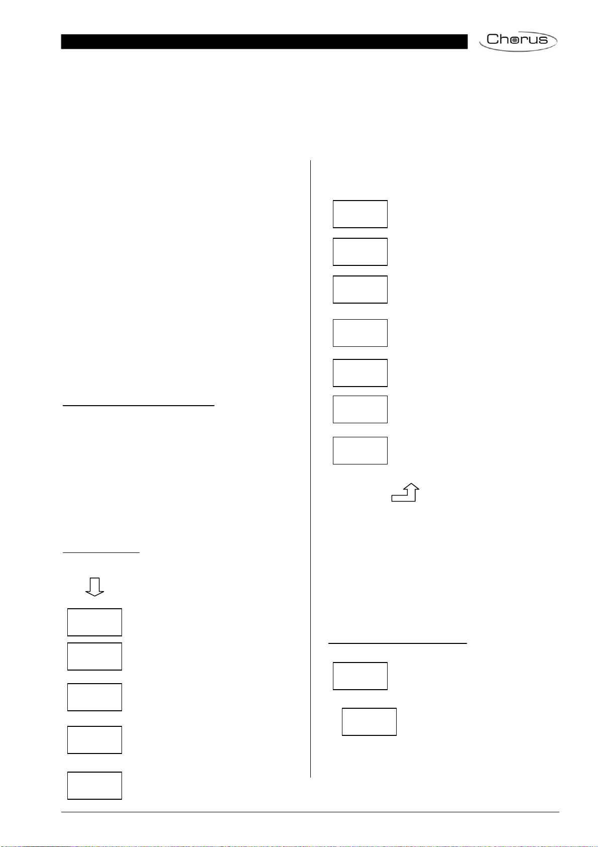
Sub-menu SCENE ASSIGNMENT – Level 2 and 3
Briefly press the Prg/Set button to change
from the main menu SCENE ASSIGNMENT to
the sub-menu. Within the menu the DALI
groups can be assigned to up to 16 possible
scenes. Individually controlled ECGs cannot
be assigned via the display. To assign indivi-
dual ECGs, you must use the website.
Briefly press the MOVE button to run through
the individual scenes. The number of the se-
lected scene is shown in the first display line.
Behind the scene number, different characters
show which of the 16 groups are assigned to
the scene. An X means that a group is as-
signed to the scene. A – means the group is
not assigned to the scene. The four characters
directly behind the scene number in the first
display line represent groups 1 - 4 (from left to
right). The 12 characters in the second display
line represent groups 5 – 16 (from left to right).
Hold the Prg/Set button to change into pro-
gramming mode. A flashing cursor on the first
X means that group 1 is selected. By briefly
pressing the Move button you can toggle be-
tween X and – symbols to choose whether you
would like to assign the group to the scene.
Briefly press the Prg/Set-button to move the
cursor to the next group. Once you have run
through all 16 groups, the setting is saved and
used during further scene programming. After
you have pressed the Prg/Set button a final
time, the display automatically returns to the
level above. Press the ESC button to return to
the level above without saving the changes
you have made.
Sub-menu GROUP TEST – Level 2 and 3
Briefly press the Prg/Set button to change
from the main menu GROUP TEST to the
sub-menu. Within the menu, groups can be
switched either individually or all together (ALL
GROUPS TEST) to test the installation.
Briefly press the MOVE button to run through
the individual groups. The number of the se-
lected group is shown in the first display line.
Hold the Prg/Set button to change into pro-
gramming mode. Briefly press the Move button
to select whether you would like to switch the
group on or off. Briefly press the Prg/Set but-
ton to execute the selected command. Press
the ESC button (or wait for about 30 seconds)
to return to the level above.
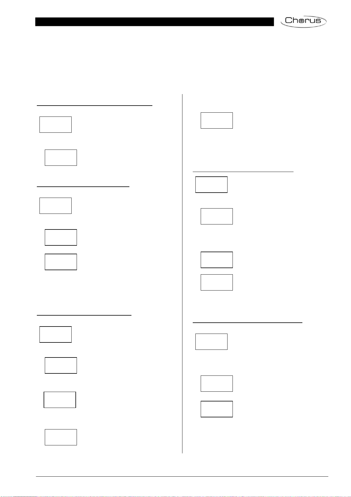
Sub-menu SCENE TEST – Level 2 and 3
Briefly press the Prg/Set button to change
from the main menu SCENE TEST to the sub-
menu. Within the menu you can invoke all
scenes for test purposes or program newly set
light scenarios into the scene.
Briefly press the MOVE button to run through
the individual scenes. The number of the se-
lected scene is shown in the first display line.
Hold the Prg/Set button to change into pro-
gramming mode. Briefly press the Move button
to choose whether you would like to invoke or
save a scene. Briefly press the Prg/Set-Taste
button to execute the selected command and
either invoke or save the scene. Press the
ESC button (or wait for about 30 seconds) to
return to the level above.
Sub-menu SYSTEM TEST – Level 2 and 3
Briefly press the Prg/Set button to change
from the main menu SYSTEM TEST to the
sub-menu. Within the menu you can check for
any potential faults.
If there is no fault, this is shown in the display.
The following faults can be recognised by the
system. They are shown in the display and
also simultaneously set off the red error LED:
•DALI short-circuit
•Lamp fault with the lamp or ECG
number being displayed
•ECG fault with the ECG number
being displayed
•No KNX bus
If there has been a DALI short-circuit, no fur-
ther faults can be recognised. For all other
fault types, several faults can be recognised at
the same time. Within the menu you can tog-
gle between the different faults by briefly
pressing the Move button. The number of the
ECG is displayed for both lamp and ECG
faults. This means that a fault can be easily
localised. Press the ESC button (or wait for
about 30 seconds) to return to the level above.
Sub-menu MAINTENANCE ECG/LAMP– Level 2 and 3
Briefly press the Prg/Set button to change
from the main menu MAINTENANCE
ECG/LAMP to the sub-menu. Within the me-
nu you can start the burn-in of a lamp and
reset the reader for its operating hours.
SCENE
ASSIGNMENT
SCENE01 XXXX
XXXXXXXXXXXX
GROUP
TEST
GROUP: 6
TEST
SCENE
TEST
SYSTEM
TEST
KNX
No Fault
LAMP 17
Fault
ECG 34
Fault
MAINTANANCE
ECG/LAMP
ECG No.: 12
GROUP: 1
SCENE03 ----
XXXX------XX
GROUP: 6
->off
SCENE: 2
TEST
SCENE: 2
->invoke
DALI
No fault
DALI
Fault

Page 10 of 45
Briefly press the MOVE button to run through
the individual ECGs. The number of the se-
lected ECG is shown in the first display line.
Line 2 shows the number of operating hours
since the last reset / burn-in.
Hold the Prg/Set button to change into pro-
gramming mode. Briefly press the Move button
to toggle between the functions BURN-IN,
RESET, BURN-IN/RESET. Briefly press the
Prg/Set button to execute the selected com-
mand. Press the ESC button (or wait for
about 30 seconds) to return to the level above.
Sub-menu CONVERTER INHIBIT MODE – Level 2
Briefly press the Prg/Set button to change
from the main menu CONVERTER INHIBIT
MODE to the sub-menu. Within the menu you
can turn on the Inhibit Mode for all connected
self-contained battery emergency lamps.
If the mains power supply is turned off within
15 minutes from activating the Inhibit Mode,
the lights do not change into emergency mode
but remain switched off. Particularly during the
initialisation phase of a building this operating
mode may be required to prevent the emer-
gency lights from being turned on constantly.
Hold the Prg/Set button to change into pro-
gramming mode. Briefly press the Prg/Set but-
ton again to activate the Inhibit Mode.
Press the ESC button (or wait for about 30
seconds) to return to the level above.
6. Control via web browser
In addition to the pushbuttons, you can also easily com-
mission the DALI via the integrated web server. For this
purpose connect the GW90872A directly to the IP
network. An RJ-45 socket is located above the KNX bus
connector at the bottom left-hand side of the device.
Use astandard patch cable to connect the device to a
switch, hub or router of the IP network. You can also use
aWLAN access point as network coupler. This means
you can commission the DALI via aportable note book,
tablet PC or mobile phone.
Once the network is physically connected, you need to
assign an IP address to the GW90872A to enable
access via the web browser. By default, all GEWISS
de-vices with an IP interface are set to DHCP address
as-signment. If there is a DHCP server in the network
the device automatically receives an IP address after
initiali-sation. This address is shown on the device
display (see above). If no DHCP service is available
or if you would rather use a fixed IP address, you
must set the address either via ETS or the device
display. You may also need to configure the sub-net
mask and standard gateway (for direct access via the
Internet). Those two parameters can only be configured
in the ETS.
Once the IP address has been assigned, load the device
website via any web browser (e.g. Microsoft Internet
Explorer, Mozilla Firefox, Apple Safari). Simply enter the
correct IP address (URL) in the browser.
Please remember that the complete URL consists of
the IP address and the prefix http:// To load a page
enter, for example http://192.168.10.71.
The following web site appears:
Use the log-in-page to assign either ‘User‘ or ‘Adminis-
trator‘ rights to a user. User rights mean that the website
functions are restricted and configuration commands are
disabled. Use this login if you would like to use the web-
site only for visualisation and operational purposes. To
commission the DALI via the website, administrator
ECG No.: 01
368 h
CONVERTER
INHIBIT MODE
ECG No.: 01
BURNIN/RES.
ECG No.: 01
BURNIN
INHIBIT
via PROG-MODE
CONVERTER
INHIBIT?

Page 11 of 45
rights are required. The images and descriptions below
are all based on the administrator display. Different
passwords for user and administrator can be set in the
ETS. The default setting for both users is ‘0‘.
Log in as administrator to access the following configura-
tion website:
The configuration page is divided into different sections.
The section at the top of the page contains the configu-
ration buttons that are required for the commissioning.
(Some of these buttons are only visible if you log in as
administrator). The fields underneath the configuration
buttons are for the 16 group and 64 ECG functions. The
bottom section contains the information and status area.
The three tabs in the footer are used to change from
general configuration to scene configuration and effect
configuration.
All operable buttons work with tool tips. This means a
description of the function appears if the cursor hovers
over the button.
6.1 Configuration buttons
The icons in the website header are used for the differ-
ent commissioning functions. They have the following
meaning:
Refresh
This function refreshes the website content. On principle,
the website is static. This means that the details on the
page are only updated when the site is first loaded. Any
faults or changes that are not made on the website itself,
such as a light status adjustment via a KNX telegram are
not automatically displayed.
New Installation
Press this button to start a new installation (reset and
teach-in process) of the connected DALI segment. At-
tention: During a new installation any previously ex-
isting configurations of the DALI segment are de-
leted.
Post-installation
Press this button to start a post-installation within the
DALI segment. Any ECGs that no longer exist are de-
leted during the post-installation process. At the same
time new devices are added.

Page 12 of 45
ECG Quick Exchange
Press this button to start an ECG quick exchange within
the DALI segment. The quick exchange is only possible
when a single faulty ECG is replaced by a new one.
Device status
Press this button to display the device status of the
gateway in the information and status area at the bottom
of the page. Click on a group or ECG field to display the
status information of the selected ECG or group.
Broadcast ON Broadcast OFF Broadcast Blink
Use these functions to simultaneously switch all ECG
lights /lamps in the DALI segment off or on or set them
to blink-mode via a DALI Broadcast telegram.
6.2 Control buttons
There are further control buttons above the ECG field.
These are used to perform ECG or group-specific opera-
tions. To carry out one of the operations, you must se-
lect the operation first and then click on the group or
ECG concerned. The selected function appears in a
white frame. Press the button again to cancel the selec-
tion.
No selection First button selected
The individual buttons have the following meaning:
Remove assignment
Use this button to remove the assignment of an ECG.
Select the button first. Then click on the ECG. If the ECG
was assigned to a group, the group assignment is de-
leted. If the ECG was marked for individual control, it is
now marked as ’not in use‘.
Assign a group
Use this button to assign an ECG to a group. First select
the button. Then click on the group. To complete the
process click on the ECG you want to assign to the
group. If the ECG was previously assigned to a group,
the previous assignment is automatically removed.
Mark ECGs for individual control
With this button an ECG is marked for individual control.
ECGs that were found during the search process first
appear with a question mark. This means that they are
considered to be ‘not in use’. If you want to enable an
ECG for individual control, select the button and then
click on the ECG concerned. The ECG is marked with
the letter ‘S‘ (Single) and is now in use.
ECG / group blink-mode
Use this button to set an individual ECG or a group to
blink-mode. To carry out this function, select the button
first. If you now press an ECG or group field, the corre-
sponding ECGs/lamps start blinking. The blink-mode is
used for identification purposes during the DALI com-
missioning process. If you press the same ECG or group
field again, the blinking stops. If you press another ECG
or group field with the button still selected, this element
starts blinking and the previously blinking lamp is turned
off.
Toggle light value
Use this button to switch the value of a group on or off.
First select the button. Then click on a group field to tog-
gle between the light values of all lamps assigned to the
group. The same process is used for ECG fields.
Swap ECG short addresses
Use this button to swap the position and thereby the
short address of two different ECGs. First select the but-
ton. Now click on two ECG fields one after the other to
physically swap their short addresses and adjust their
position in the list. This function is required to sort the
random ECGS into a specific order after a new installa-
tion. You should only use this function directly after a
new installation. Later use should be avoided as the
parameters set in the ETS are not swapped in line
with the addresses.

Page 13 of 45
6.3 ECG fields
The ECG and group entries on the website mean that
the user can see the complete function and failure status
of a connected DALI segment at a glance. The ECG
fields are numbered from 1 – 64. The number is shown
in the bottom left-hand corner of the field and corre-
sponds to the ECG short address within the DALI seg-
ment. If an ECG is found during the search process (new
and post-installation), a lamp or battery icon is inserted
in the field. The battery icon symbolises an ECG for self-
contained battery emergency lights (device type 1). All
other device types (without battery) are shown with a
lamp symbol. If in the ETS an ECG is configured as
emergency luminaire with central battery, a separate
icon is displayed. The following icons are available:
ECG
ECG for self-contained battery emergency lamp
non-switchable
ECG for self-contained battery emergency lamp
switchable
ECG with central battery supply
The value and failure status of an ECG is symbolised by
different icon and background colours.
ICON light grey => Lamp switched off
ICON yellow => Lamp switched on
ICON red => Lamp failure
Red background => ECG failure
The assignment of an ECG is also shown in the field.
Newly found devices are marked as ‘not assigned‘ via a
‘?’ symbol above the icon. When an ECG is assigned to
a group, the group number replaces the ‘?’ symbol. If an
ECG is used for individual control, it is marked with the
letter ‘S‘ (Single).
ECG not in use
ECG in use for individual control
ECG with group assignment (e.g. group 3)
6.4 Group fields
As for the ECG fields, the group fields show the status of
a group. However, the display is limited to the switch
status. No failure status is graphically displayed.
ICON light grey => group switched off
ICON yellow => group switched on
If you switch a group or ECG via the website, its status is
automatically updated and displayed on the site. How-
ever, if the switch command was initiated externally via a
KNX telegram, the status is not automatically updated.
To display the correct status, press the refresh button or
re-load the web page.
6.5 Information and status fields
The bottom section of the configuration website shows
status information for the device as a whole or for a se-
lected group or a selected ECG.
When the website is first loaded, the status information
always applies to the whole device giving you the oppor-
tunity to see the number of connected lamps, ECGs and
converters, as well as faults and fault rate at a glance.
The green colour means that no fault has occurred. Oth-
erwise the colour changes to red.
This information can be displayed at any time by press-
ing the device status button in the configuration bar at
the top of the site.

Page 14 of 45
To display the status information of a group, click on one
of the 16 group fields.
In addition to the number of devices and converters and
the individual failure types, the total failure rate is shown.
Please remember that the rate is calculated as a per-
centage of the total number of ECGs and converters in
the group. Use the Name field to enter a user-friendly
name for the group. The maximum number of characters
is 10. Press the √-button to confirm your entry. The
name is now saved on the gateway and loaded into the
ETS during the next synchronisation.
To display the status information of an ECG, click on one
of the 64 ECG fields. Choose from one of the following
options: General, Run Hours, Burn-in and Test
Use the name field on the General page to enter a user-
friendly name for the ECG. The maximum number of
characters is again 10. Press the √-button to confirm
your entry. The name is now saved on the gateway and
loaded into the ETS during the next synchronisation.
An ICON appears behind the word Alarm if a fault or
alarm has occurred. The meaning of the icons is as fol-
lows:
Lamp failure
ECG failure
Converter failure
Life cycle exceeded
An ICON appears behind the word Mode if the ECG is
not in normal mode. The meaning of the icons is as
follows:
Permanent mode
Panic mode
Central battery test mode
Burn-in mode
Click on the Run Hours tab in the header to see the ac-
cumulated operating hours of a lamp since its last reset
as well as the maximum life span that was configured in
the ETS. Use the button on the right to reset the counter
to 0.
Click on the Burn-in tab in the header to start and stop
the burn-in mode for the selected ECG.
The maximum burn-in time that was configured in the
ETS and the already completed burn-in time are also
displayed.
If the selected ECG is a device for self-contained battery
emergency lights, you can also click on the Test tab.

Page 15 of 45
This display shows the type of test, test result and date
and time of the last test. The status bar shows the failure
flags. A green bar means that the test was positive. A
red bar signals a negative test result.
You can use the buttons on this page to manually start a
test (Execute Test). The icons underneath have the fol-
lowing meaning:
Battery Test
Functional Test
Long Duration Test
Please remember that the website is static and is not
automatically updated after the test has finished. If you
would like to display the result of a manually activated
test, please press the ’Update test result’ button first.

Page 16 of 45
7. ETS special and commissioning functions
As previously described in chapter 4, you can choose
eiher type A ‘Normal mode‘ or type B ‘Extended mode‘
for the DALI commissioning. Depending on the mode
you choose, different special functions and pages are
available in the ETS.
7.1 Special functions in ‘Normal mode‘
7.1.1 Synchronisation with the connected DALI seg-
ment
When you first load the parameter page, the parameters
and groups for all possible 64 ECGs and 16 groups are
displayed. In ETS mode A it is possible to simplify the
commissioning and to bring the application in line with
the real conditions of the connected DALI segment. To
do so, you need to synchronise the application with the
installation first.
Start the synchronisation via the sync button in the bot-
tom right-hand corner of the main window. Depending on
the size of the installation the synchronisation may take
a few seconds. A bar at the bottom of the page shows
how far the synchronisation has progressed. When the
synchronisation is complete, only the objects and pa-
rameters of those ECGs that are physically connected to
the device are shown.
In addition, the device types and, if applicable, the group
asignments are also automatically set.
If during the synchronisation a device type is found that
does not match with the current settings in the ETS, a
warning message appears. Please acknowledge the
message by pressing yes or no.
By default the synchronisation of the ETS is performed
via the KNX network. If the gateway is already correctly
integrated into the IP network and a corresponding IP
address has been assigned, the synchronisation can
also be performed via Ethernet. In this case, all you
need to do is enter the correct IP address of the device
into the tool bar at the top of the window and tick the
check-box in front of the bar. Alternatively, you can
press the Read IP Address button to set the IP address
of the selected device without manual entry.

Page 17 of 45
The synchronisation compares the application to the
data of the connected DALI segment. This means that
you should always synchronise when you change
the system structure or expand the system.
7.1.2 User-friendly names for ECGs and groups
To make the configuration as easy as possible for the
user, it makes sense to choose user-friendly names for
ECGs and groups. Any names need to be assigned on
the website in ETS Mode A directly during the identifica-
tion. Please remember to press the confirm button next
to the entry field after entering a name.
Use the ‘Load Description’ command in the Tools menu
to load the names directly into the ETS. The names are
shown in brackets next to the corresponding device.
As loading the names via KNX can take quite some time,
you should use the Ethernet connection for this process.
Before starting the process, please make sure you set
the right IP address and tick the check-box in front of the
address.
7.2 Special functions in ‘Extended Mode‘
If you select ‘extended Mode‘ (Mode B) for the DALI
commissioning (see chapter 4), an additional menu ap-
pears underneath the main menu bar with the entries
’Parameter‘, ’Commissioning‘, ’Scenes‘ and ’Effects‘
Use the menu item ‘Parameter‘ to set the ETS parame-
ters in the same way as in mode A. However, please
remember that in mode B all parameters are visible be-
cause the parameter settings can be performed inde-
pendently of the actual system. Simplifying the parame-
ters and objects by synchronising with the system is not
possible in this mode.
The menu item ‘Commissioning‘ is described in more
detail in the next chapter. For a description of menu
items ‘Scenes‘ and ‘Effects‘, please see chapter 11.

Page 18 of 45
7.2.1 Preparing and planning the DALI commission-
ing in ‘Extended Mode‘
In Mode B, the menu item ‘Commissioning‘ opens an
additional page which is not available in ‘normal mode‘.
This page is used both to plan the installation in advance
of the commissioning and to perform the actual DALI
commissioning later on (identification and assignment of
ECGs).
The structure of the commissioning page is as follows:
The group configuration is displayed on the left-hand
side in a tree structure. The area in the middle shows the
ECG configuration and names in a table format. On the
right hand side is a list of all devices found in the system,
which have not yet been identified. During the planning
stage this part is empty as the ETS is not yet connected
to the system.
To start with you should plan and name the ECGs. Use
the description field in the ECG configuration to enter a
name (light number, room number, etc.)
The maximum number of characters available for names
in the ETS plug-in is 30. Whilst, in principle, the names
are also transferred to the device website, it is important
to remember that the website will display no more than
the first ten characters of the name entered in the plug-
in.
If you confirm your entry with the return button, the cur-
sor automatically jumps to the next ECG field. This
makes the naming process easy and secure.
Once you have planned the ECGS, you should assign
the groups. There are two ways to assign groups via
drag-and-drop:
1.) Use the mouse to select an ECG in the ECG
configuration field in the middle and drag it to
the left dropping it above the required group in
the group tree.
2.) Use the mouse to select an ECG from the
group directory’s top category ‘not assigned‘
and move it down the directory dropping it
above the required group.
Once an ECG has been assigned to a group via drag
and drop, the group number is automatically displayed in
the ‘group number‘ field of the ECG configuration table.
You can enter a user-friendly name for the group in the
‘group description‘ field. ECG and group names are
automatically shown in the group configuration directory
(displayed in brackets) as well as in the description of
the ETS communications objects. Having user-friendly
names makes linking the group addresses with the
communications objects much easier for the system
integrator.
As soon as an ECG has been assigned to a group, it is
no longer available for individual control. The parameters
and communication objects are adjusted accordingly
following the group assignment. ECGs that have not

Page 19 of 45
been assigned to a group are automatically regarded as
ECGs for individual control.
Please see chapter 11 for the planning and setting of
scenes and effects.
7.2.2 DALI commissioning in ‘Extended Mode‘
Once the planning, parameter setting and linking of
group addresses have all been completed the DALI
segment can be commissioned. To do so, please con-
nect the commissioning PC with the ETS to the KNX
system via an interface (RS-232, USB or IP). Once the
connection is active, you need to program the physical
address of the gateway. The communication between
the plug-in and the gateway is based on the physical
address (or possibly on the IP address, see below).
Use the ‘commissioning‘ page and the ‘tools‘ menu to
start the teach-in process of the connected DALI seg-
ment.
Please remember that the selection shown above is only
visible in the ‘Tools‘ menu if you have selected the
‘commissioning‘ page. The elements displayed always
depend on the setting selected in the menu bar.
During the teach-in process all ECGs are automatically
recognised and each ECG is assigned a short address
from 0 - 63. Depending on the size of the connected
DALI segment the process can take up to 3 minutes.
A bar in the bottom right hand corner indicates how far
this process has progressed. The number of ECGs that
have so far been found is also shown (in brackets).
Once the teach-in process is complete, all ECGs that
have been found are displayed in the list of non-
identified devices on the right-hand side.
You can now identify the devices by switching the corre-
sponding lamp on or off. If you select an ECG and press
the right mouse button, a context menu appears from
which you can select the required function.
Alternatively, you can also tick the box ‘Automatic blink
mode‘. In this case, the blink mode starts by itself when
a device is selected. The context menu is also available
at group and gateway level. During the identification
process it might be useful to switch certain groups or all
connected lamps on or off. If you select the main item
‘group configuration‘, you can use the right mouse button
to send broadcast commands for on, off and blinking.
Once an ECG has been identified, you can drag and
drop it onto the previously planned element in the ECG
configuration table.
Once an ECG has been dragged into the ECG configu-
ration table, it disappears from the list of non-identified
ECGs. The ‘PLAN‘ flag in the configuration table shows
that the ECG has been assigned to the planned element.
Table of contents
Other Gewiss Gateway manuals
Popular Gateway manuals by other brands

DIGITAL YACHT
DIGITAL YACHT iKonvert USB Installation and instruction manual

Amit
Amit ODG761AM-0T1 user manual

ICP CON
ICP CON GW-7434D Quick start user guide

Elcon
Elcon ELCONnect next BIG 101 Series user manual

Sagem
Sagem MA 500+ Series installation guide

Honeywell
Honeywell W8735G installation instructions