GEZE Slimdrive EMD-F-IS User manual

Slimdrive EMD
F-IS
EN Additional installation instructions
164990-00

Slimdrive EMD F-IS
2
Contents
Symbols and illustrations..................................................................................................................................................3
Product liability.....................................................................................................................................................................3
1 Safety ...........................................................................................................................................................................3
1.1 Proper use............................................................................................................................................................................................................3
1.2 Standards.............................................................................................................................................................................................................3
1.3 Reference documents .....................................................................................................................................................................................3
1.4 Safety notices .....................................................................................................................................................................................................4
2 Product description................................................................................................................................................4
2.1 Areas of application .........................................................................................................................................................................................4
2.2 Basic structure and extension ......................................................................................................................................................................4
3 Types of installation................................................................................................................................................7
3.1 Use of the roller lever types depending on the type of installation...............................................................................................7
3.2 Type of installation transom installation hinge side............................................................................................................................7
3.3 Type of installation transom installation opposite hinge side.........................................................................................................7
3.4 Installation of the drives and IS connection of active and passive leaves....................................................................................8
3.5 Replace brake unit on the active leaf drive .......................................................................................................................................... 13
4 CE mark according to EN 1158 ........................................................................................................................ 19
5 Commissioning ..................................................................................................................................................... 19
6 Service and maintenance.................................................................................................................................. 19
6.1 Maintenance requirements........................................................................................................................................................................ 19
6.2 Additional service work for Slimdrive EMD F-IS systems ................................................................................................................ 19
6.3 Troubleshooting ............................................................................................................................................................................................ 19

Slimdrive EMD F-IS
3
Safety
Symbols and illustrations
Warning notices
Warning notices are used in these instructions to warn you of property damage and personal injury.
XAlways read and observe these warning notices.
XFollow all measures that are labelled with the warning symbol and warning word .
Warning
symbol
Warning word Meaning
ATTENTION Danger to persons.
Non-compliance can result in death or serious injuries.
Further symbols and means of representation
Important information and technical notes are highlighted to explain correct operation.
Symbol Meaning
Means “important note”
Means “additional Information”
XSymbol for an action: there is something you must do here.
XIf there are several actions to be taken, keep to the given order.
Product liability
In compliance with the liability of the manufacturer for his products as dened in the German "Product Liability
Act", compliance with the information contained in this brochure (product information and intended use, misuse,
product performance, product maintenance, obligations to provide information and instructions) must be en-
sured. Failure to comply releases the manufacturer from their statutory liability.
1 Safety
1.1 Proper use
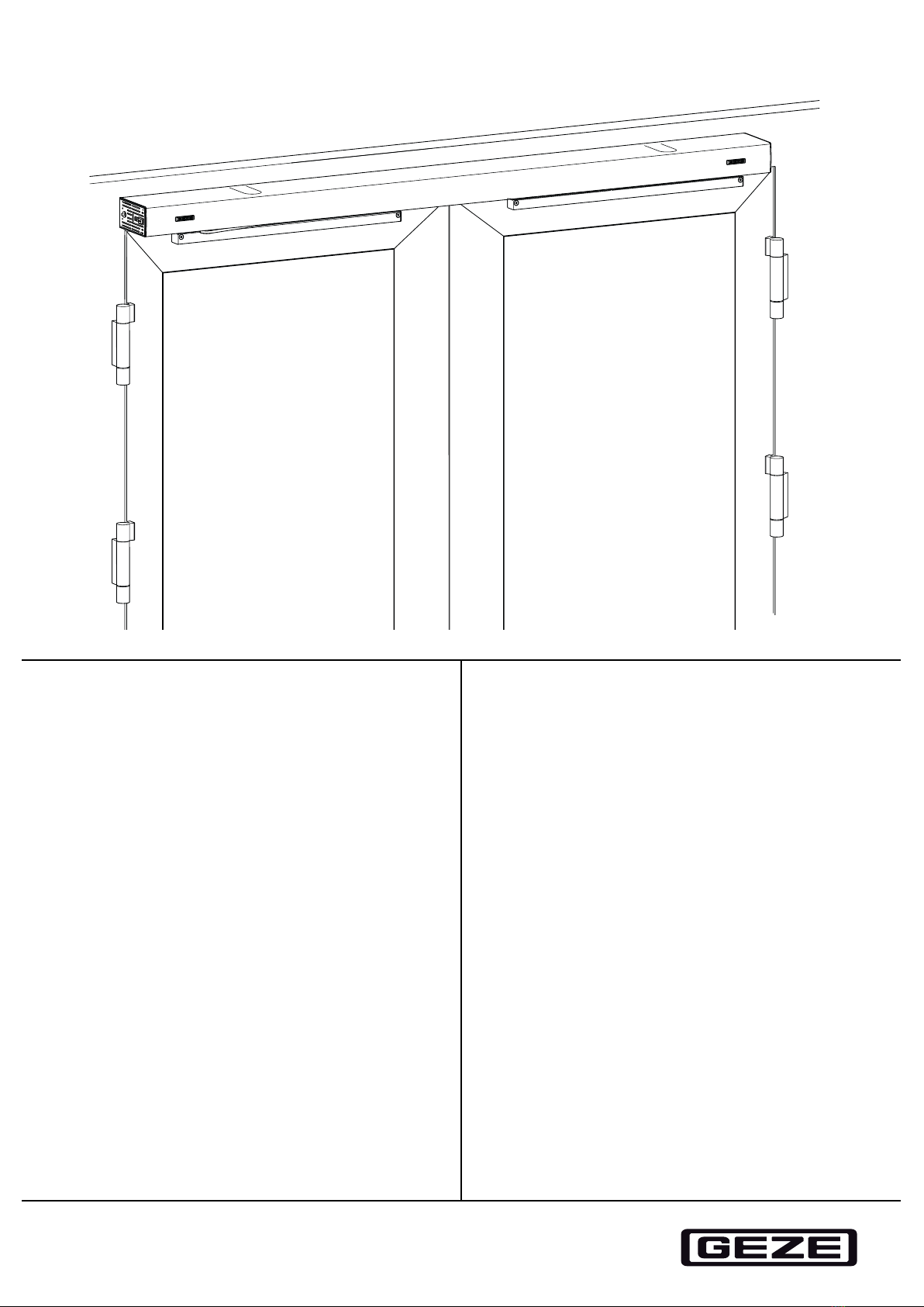
The door closing sequence control Slimdrive EMD F-IS has been designed for automatic control during the
closing of double-leaf single-action swing doors. The components required supplement the Slimdrive EMD-F
drive and must be installed according to these instructions.
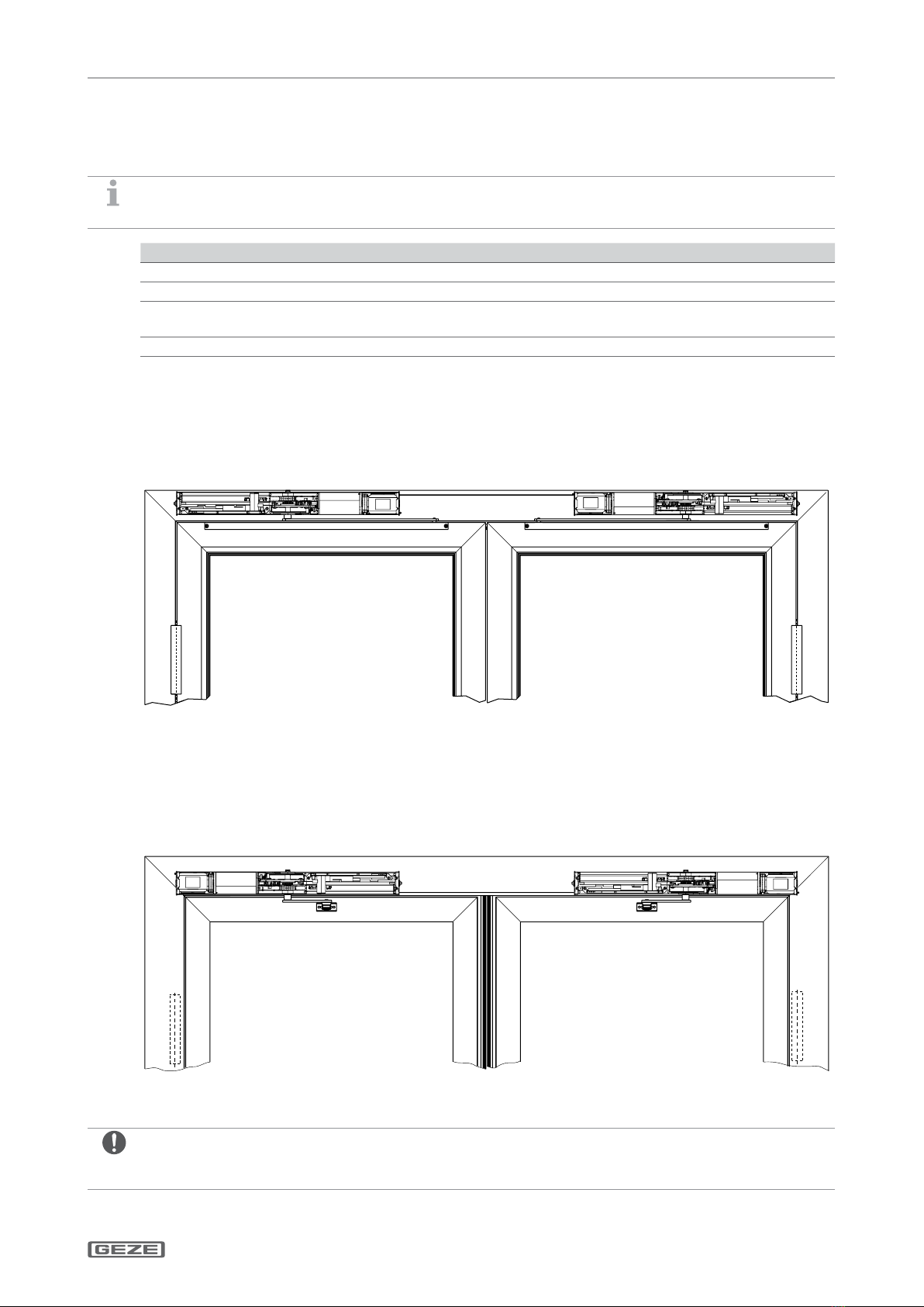
The door closing sequence control EMD F-IS
àis designed for use on re and smoke protection doors. Permitted installation types:
àTransom installation opposite hinge side with link arm
àTransom installation hinge side with roller guide rail
àMay be used on escape and rescue route doors.
àMay not be used for potentially explosive areas.
Any other use than the proper use, such as permanent manual operation, as well as all changes to the product are
impermissible.
Observe the "GEZE Product information for door closers".
1.2 Standards
When installing the closing sequence control, the applicable standards must be observed, see the Slimdrive EMD
/ EMD-F installation instructions.
DIN EN 1158 is also applicable
1.3 Reference documents
àInstallation instructions Slimdrive EMD/EMD-F
àWiring diagram Slimdrive EMD/EMD-F
àCable plan Slimdrive EMD/EMD-F
The diagrams are subject to change without notice. Use only the most recent version.

Slimdrive EMD F-IS
4
Product description
1.4 Safety notices
The description of the overall installation of the drive is not the subject of these instructions. This information can
be found in the installation instructions Slimdrive EMD-F.
All the necessary safety notices for conversion or extension to a double-leaf version can be found on the follow-
ing pages.
2 Product description
2.1 Areas of application
See installation instructions EMD-F for mechanical and electrical data.
2.2 Basic structure and extension
2.2.1 Drive Slimdrive EMD F-IS – active leaf transom installation hinge side
1 Wire rope guide
2 Ventilation lever brake K-BS
3 IS-Brake

Slimdrive EMD F-IS
5
Product description
2.2.2 Drive Slimdrive EMD F-IS – passive leaf transom installation hinge side
1 Trip rocker
2 Wire rope guide
2.2.3 Drive Slimdrive EMD F-IS – active leaf transom installation opposite hinge side
1 Ventilation lever brake K-BGS
2 Wire rope guide
3 IS-Brake

Slimdrive EMD F-IS
6
Product description
2.2.4 Drive Slimdrive EMD F-IS – passive leaf transom installation opposite hinge side
1 Trip rocker
2.2.5 Accessories
1 Wire rope
2 Side part for continuous hood
3 Side part for intermediate cover kit
For other accessories see installation instructions Slimdrive EMD-F.

Slimdrive EMD F-IS
7
Types of installation
3 Types of installation
3.1 Use of the roller lever types depending on the type of installation
Also heed the marking on the roller lever.
Type of installation Installation side Roller lever
Transom installation hinge side DIN left Standard
DIN right Standard
Transom installation opposite
hinge side
DIN left Door leaf left-hand
DIN right Door leaf right-hand
3.2 Type of installation transom installation hinge side
With this type of installation, only roller guide rail and lever can be used. Details about permissible sot depth,
door overlap and installation holes can be found in the Slimdrive EMD-F installation instructions.
3.3 Type of installation transom installation opposite hinge side
With this type of installation, both link arms as well as roller guide rail and lever can be used. Details about
permissible sot depth, door overlap and installation holes can be found in the Slimdrive EMD-F installation
instructions.
Door leaf installation with mechanical, integrated closing sequence control is not possible.
Passive leaf Active leaf

Slimdrive EMD F-IS
8
Types of installation
3.4 Installation of the drives and IS connection of active and passive leaves
Installation of the drives and levers see Slimdrive EMD-F installation instructions.
3.4.1 Transom installation hinge side
XMove active leaf to open position.
XFix the passive leaf with approx. 10° door angle.
XHook the wire rope(2) with the spherical button in
the trip rocker(1) of the drive.
XLay the wire rope(2) from the passive leaf drive
through the slots in the side parts and the wire rope
guides(3) to the IS_brake on the active leaf drive.

Slimdrive EMD F-IS
9
Types of installation
XConnect the wire rope(2) with the wire rope tighten-
er(5) and headless pin(6) to the ventilation lever(4)
so that the rope is taut but the ventilation lever is not
yet deected.
XShorten the projecting wire rope to a suitable length.
Note the correct wire rope setting (see“Correct wire
rope setting” on page 11).

Slimdrive EMD F-IS
10
Types of installation
3.4.2 Transom installation opposite hinge side
XMove active leaf to open position.
XFix the passive leaf with approx. 10° door angle.
XHook the wire rope(3) with the spherical button(1) in the
trip rocker(2) of the passive leaf drive.
XLay the wire rope from the passive leaf drive through the
slots in the side parts and the wire rope guides(4) to the
IS_brake on the active leaf drive.
XConnect the wire rope(3) with the wire rope tightener(5)
and headless pin(6) to the ventilation lever(7) so that the
rope is taut but the ventilation lever is not yet deected.
XTighten headless pin (Allen key 1.5mm) in the wire rope
tightener(5).
The wire rope is attached.
XShorten the projecting wire rope to a suitable length.
Note the correct wire rope setting (see“Correct wire rope
setting”on page 11).

Slimdrive EMD F-IS
11
Types of installation
Correct wire rope setting
àThe rope must be slightly tensioned in the given door position, but must not actuate the ventilation lever.
àThe ventilation lever must return to its starting position when opening the passive leaf and must not lock in a
self-locking position.
SW 2,5
XSet the retaining action of the IS brake with the hollow set-screw(1).
3.4.3 Function check
XOpen active leaf to door angle of 90°.
XOpen passive leaf to door angle of 30°.
XAllow passive leaf to close.
From a door angle of approx. 5–10° for the passive leaf, the active leaf must start to close.
XOpen the passive leaf again to approx. 30°, the active leaf then has to stop again.
Further test requirements: see national/international standards and regulations.
àSee the wiring diagram Slimdrive EMD-F for the electrical connection between the active and passive leaves.
XDuring installation, take care that there is no cable in the range of movement of the ventilation lever.
XMake sure the cables are secured suciently well.

Slimdrive EMD F-IS
12
Types of installation
3.4.4 Type of installation transom installation hinge side
3.4.5 Type of installation transom installation opposite hinge side

Slimdrive EMD F-IS
13
Types of installation
3.5 Replace brake unit on the active leaf drive
3.5.1 Drive for transom installation hinge side
Loosen the wire rope attachment in the ventilation lever
XLoosen headless pin(1) with an Allen key
SW1.5mm in the wire rope tightener.
XRemove wire rope(5) from the wire rope tight-
ener, ventilation lever(2), wire rope guide(3) and
side part(4).
Dismantle side part and transformer
XLoosen 2 screws(3).
XRemove side part(2) from transformer.
XUnscrew the screws(1).
XRemove transformer(4) and position so that the
transformer's weight does not excessively pull on
the connection cable.

Slimdrive EMD F-IS
14
Types of installation
Dismantle brake unit
XLoosen hex screw SW5.5mm(1) on the retaining
plate(2).
XTurn retaining plate(2) to one side.
XRemove brake unit(3) with ventilation lever(4)
from the motor shaft.

Slimdrive EMD F-IS
15
Types of installation
XLoosen M4 countersunk screw(6) with Allen key
SW2.5mm and remove ventilation lever(4) from
the brake unit(3).
XFit the ventilation lever(4) in the correct position
with M4 countersunk screw(6) on the new brake
unit. Tightening torque 2.5Nm
XInsert new brake unit(3) in the correct position
on the motor shaft.
The label "OHS"(5) must be visible on the
housing.
XReturn the retaining plate(2), tighten hex
screw(1) with 1Nm.
For assembly of transformer and side part, check
the fastening and laying of the connection cable are
secure.
XAssemble transformer and side part.
Tightening torque 2.5Nm.
XCheck wire rope for damage, replace wire rope if
necessary.
XThread wire rope through side part, wire rope
guide, ventilation lever and wire rope tightener.
XFasten wire rope tightener to the wire rope. For
setting of the wire rope and the IS mechanism,
see chapter 3.4.1.

Slimdrive EMD F-IS
16
Types of installation
3.5.2 Drive for transom installation opposite hinge side
Loosen the wire rope attachment in the ventilation lever
XLoosen headless pin(1) with an Allen key
SW1.5mm in the wire rope tightener.
XRemove wire rope(3) from the wire rope tighten-
er, ventilation lever(2) and side part.
Dismantle side part and transformer
XLoosen 2 screws(3).
XRemove side part(2) from transformer.
XUnscrew the screws(1).
XRemove transformer(4) and position so that the
transformer's weight does not excessively pull on
the connection cable.

Slimdrive EMD F-IS
17
Types of installation
Dismantle brake unit
XLoosen hex screw SW5.5mm(1) on the retaining
plate(2).
XTurn retaining plate(2) to one side.
XRemove brake unit(3) with ventilation lever(4)
from the motor shaft.

Slimdrive EMD F-IS
18
Types of installation
XLoosen M4 countersunk screw(6) with Allen key
SW2.5mm and remove ventilation lever(4) from
the brake unit(3).
XFit the ventilation lever(4) in the correct position
with M4 countersunk screw(6) on the new brake
unit. Tightening torque 2.5Nm
XInsert new brake unit(3) in the correct position
on the motor shaft.
The label "OHS"(5) must be visible on the hous-
ing.
XReturn the retaining plate(2), tighten hex
screw(1) with 1Nm.
For assembly of transformer and side part, check
the fastening and laying of the connection cable are
secure.
XAssemble transformer and side part.
Tightening torque 2.5Nm.
XCheck wire rope for damage, replace wire rope if
necessary.
XThread wire rope through side part, wire rope
guide, ventilation lever and wire rope tightener.
XFasten wire rope tightener to the wire rope. For
setting of the wire rope and the IS mechanism,
see chapter 3.4.1.

Slimdrive EMD F-IS
19
CE mark according to EN 1158
4 CE mark according to EN 1158
The Slimdrive EMD F-IS has the following classication according to EN1158:1997 + A1:2002:
XAx the CE mark sticker on the inside of the cover.
5 Commissioning
See installation instructions and wiring diagram Slimdrive EMD-F for electrical connection, spring force setting
and teaching process.
6 Service and maintenance
6.1 Maintenance requirements
The maintenance work on the door closing sequence selector must be carried out by an expert during the
maintenance cycle of the Slimdrive EMD and Slimdrive EMD-F drives.
See EMD-F installation instructions for maintenance instructions.
6.2 Additional service work for Slimdrive EMD F-IS systems
Danger of mechanical damage to IS trigger parts.
XBefore dismantling or unhooking the link arms or roller lever, loosen wire cable coupling rst.
Otherwise the drive shaft will continue to rotate around the output shaft.
àCheck the condition of the wire rope for any damage to the sheathing.
àMeasure the retaining action of the IS brake in the area of the active leaf, if necessary increase the retaining
action, see “Correct wire rope setting” on page 11.
The wire rope must be replaced if necessary.
6.3 Troubleshooting
For troubleshooting and fault elimination see the fault table in the wiring diagram, "Fault messages" section.

Germany
GEZE GmbH
Niederlassung Süd-West
Tel. +49 (0) 7152 203 594
E-Mail: leonberg.de@geze.com
GEZE GmbH
Niederlassung Süd-Ost
Tel. +49 (0) 7152 203 6440
E-Mail: [email protected]
GEZE GmbH
Niederlassung Ost
Tel. +49 (0) 7152 203 6840
E-Mail: [email protected]
GEZE GmbH
Niederlassung Mitte/Luxemburg
Tel. +49 (0) 7152 203 6888
E-Mail: [email protected]
GEZE GmbH
Niederlassung West
Tel. +49 (0) 7152 203 6770
E-Mail: duesseldorf[email protected]
GEZE GmbH
Niederlassung Nord
Tel. +49 (0) 7152 203 6600
E-Mail: hamburg.de@geze.com
GEZE Service GmbH
Tel. +49 (0) 1802 923392
E-Mail: service-info.de@geze.com
Austria
GEZE Austria
E-Mail: [email protected]
www.geze.at
Baltic States
GEZE GmbH Baltic States oce
E-Mail: oce[email protected]om
www.geze.com
Benelux
GEZE Benelux B.V.
E-Mail: [email protected]
www.geze.be
www.geze.nl
Bulgaria
GEZE Bulgaria - Trade
E-Mail: oce[email protected]om
www.geze.bg
China
GEZE Industries (Tianjin) Co., Ltd.
E-Mail: [email protected]
www.geze.com.cn
GEZE Industries (Tianjin) Co., Ltd.
Branch Oce Shanghai
E-Mail: [email protected]
www.geze.com.cn
GEZE Industries (Tianjin) Co., Ltd.
Branch Oce Guangzhou
E-Mail: [email protected]
www.geze.com.cn
GEZE Industries (Tianjin) Co., Ltd.
Branch Oce Beijing
E-Mail: [email protected]
www.geze.com.cn
France
GEZE France S.A.R.L.
E-Mail: france.fr@geze.com
www.geze.fr
Hungary
GEZE Hungary Kft.
E-Mail: oce[email protected]
www.geze.hu
Iberia
GEZE Iberia S.R.L.
E-Mail: [email protected]
www.geze.es
India
GEZE India Private Ltd.
E-Mail: oce-india@geze.com
www.geze.in
Italy
GEZE Italia S.r.l
E-Mail: [email protected]
www.geze.it
GEZE Engineering Roma S.r.l
E-Mail: [email protected]
www.geze.it
Poland
GEZE Polska Sp.z o.o.
E-Mail: geze.pl@geze.com
www.geze.pl
Romania
GEZE Romania S.R.L.
E-Mail: oce-romania@geze.com
www.geze.ro
Russia
OOO GEZE RUS
E-Mail: oce-russia@geze.com
www.geze.ru
Scandinavia – Sweden
GEZE Scandinavia AB
E-Mail: sverige.se@geze.com
www.geze.se
Scandinavia – Norway
GEZE Scandinavia AB avd. Norge
E-Mail: norge.se@geze.com
www.geze.no
Scandinavia – Denmark
GEZE Danmark
E-Mail: [email protected]
www.geze.dk
Singapore
GEZE (Asia Pacic) Pte, Ltd.
E-Mail: [email protected]
www.geze.com
South Africa
GEZE South Africa (Pty) Ltd.
E-Mail: [email protected].za
www.geze.co.za
Switzerland
GEZE Schweiz AG
E-Mail: schweiz.ch@geze.com
www.geze.ch
Turkey
GEZE Kapı ve Pencere Sistemleri
E-Mail: oce[email protected]om
www.geze.com
Ukraine
LLC GEZE Ukraine
E-Mail: oce[email protected]
www.geze.ua
United Arab Emirates/GCC
GEZE Middle East
E-Mail: [email protected]
www.geze.ae
United Kingdom
GEZE UK Ltd.
E-Mail: info[email protected]
www.geze.com
GEZE GmbH
Reinhold-Vöster-Straße 21–29
71229 Leonberg
Germany
Tel.: 0049 7152 203 0
Fax.: 0049 7152 203 310
www.geze.com
Other manuals for Slimdrive EMD-F-IS
1
Table of contents
Other GEZE DC Drive manuals
Popular DC Drive manuals by other brands

Wittenstein
Wittenstein Simco SIM2050D operating manual

UNI Geräte
UNI Geräte MG X Series operating instructions

Rhymebus
Rhymebus RM6S2 Series Parameter manual

Lenze
Lenze EZN3B0055H060N003 Mounting instructions

Dorner
Dorner 2200 series Installation, maintenance & parts manual

Allen-Bradley
Allen-Bradley PowerFlex 6000T Original instructions