Gascat ARES N Instruction manual

Installation, Operation & Maintenance Manual
Pressure Regulating Valve
Model ARES N
Installation, Operation and Maintenance Manual
Pressure Regulating Valve – Model Ares N
MI–42
Prepared by Verified by Approved by CSQ Date Revision Page
José Junior Vanízio Lizo Jamerson 24/03/17
02 2 of 21
TABLE O CONTENTS
1.0 GENERAL WARNING 3
1.1
PRE-CO ISSIONING
INSTRUCTIONS 3
1.2
-
HEALTH
&
SAFETY 3
1.2.1 - NOISE 3
1.2.2 - INSTALLATION 3
1.2.3 - OPERATION 3
1.2.4. MAINTENANCE 4
2.0 INTRODUCTION 4
2.1
SCOPE 4
2.2
DESCRIPTION 4
2.3
SPECIFICATIONS 4
2.3.1 AVAILABLE CONFIGURATIONS
4
2.3.2 AVAILABLE CONNECTIONS 4
2.3.3 TEMPERATURE LIMITS 4
2.3.4 FLOW RATE TABLE 5
2.3.5 MAXIMUM WORK PRESSURE 6
2.3.6 SET POINT PRESSURES - ARES N 6
2.3.7 ACCURACY AN LOCK UP 6
2.3.8 SET POINT PRESSURES - SSV G-10 7
2.3.9 ACCURACY - SSV G-10 7
3.0 - OPERATION PRINCIPLE 7
3.1
ARES
N
REGULATOR
-
BASIC
INSTALLATION 7
3.2
E BEDED
BLOKING
VALVE
-
ODEL
G-10 9
4.0 - INSTALLATION 9
4.1
FILTER 9
4.2
CLEANING 9
4.3
FLOW
DIRECTION
AND
SYSTE
INTEGRITY 9
4.4
RECO ENDED
INSTALLATION
SCHE E 11
4.4.1 SINGLE REGULATOR 11
4.5
CO ISSIONING
AND
START-UP 11
4.5.1 GENERAL RECOMMEN ATIONS 11
4.5.2 COMMISSIONING (SINGLE REGULATOR SPAN) 12
4.5.3 THE BACK-UP LINE SET-UP 14
4.5.4 LIST OF RECOMMEN E TOOLS 14
5.0 TROUBLE SHOOTING 15
6.0 MAINTENANCE 15
6.1
RECO ENDED
REPAIR
PARTS
AND
KITS 17
6.2
PROCEDURE
FOR
ARES
N
REGULATOR
DISASSE BLY 19
6.3
PROCEDURE
FOR
SSV
G-10
DISASSE BLY 21
6.4
PROCEDURE
FOR
REGULATOR
ARES
N
ASSE BLY 21
Installation, Operation and Maintenance Manual
Pressure Regulating Valve – Model Ares N
MI–42
Prepared by Verified by Approved by CSQ Date Revision Page
José Junior Vanízio Lizo Jamerson 24/03/17
02 3 of 21
1.0 GENERAL WARNING
1.1 PRE-COMMISSIONING INSTRUCTIONS
It should rest clearly understood that the information presented in these Commissioning Instructions is not intended to
revoke or replace instructions determined by any competent body, and reference shall be made to the relevant Standards
and/or to existing recommendations on the subject.
Before commissioning, the execution of appropriate "Cleaning and Purification Procedures" is implied. Furthermore, all
instructions on "Pressurization" and the "Work Standards on Health and Safety" must be strictly met.
Valves' manufacturers recommendations, such as "open slowly" or "open very slowly" must be strictly observed.
1.2 HEALTH & SAFETY
Regulators, valves and other pressurized components that contain toxic gases, flammable or other hazardous products,
are potentially dangerous if not operated and maintained correctly. It is mandatory that all users of this equipment are
properly educated and guided on potential dangers, and get assured that the personnel responsible for their installation,
testing, commissioning, operation, and the plant maintenance are competent to perform these tasks. Instruction manuals
are provided for the operators’ guidance, but it is assumed that they have a basic level of knowledge. If there are any
questions or ambiguities that affect the proper procedures ask Gascat Ind. e Com. Ltda., who will be pleased to advise or
provide the relevant service or instruction. TAKE NO RISKS. Our phone, fax and e-mail numbers are the following:
Gascat Indústria e Comércio Ltda.
Rodovia SP 73, 1141 - Indaiatuba / São Paulo.
CEP 13347-990
Phone: 55 19 3936-9300
Fax: 55 19 3935-6009
Email: vendas@gascat.com.br / [email protected].br
The items that follow, although not exhaustive, provide guidance on possible sources of danger to health and safety.
1.2.1 NOISE
Regulators, valves and pressure reducers can generate high levels of noise, which may be harmful to persons exposed
to them for long periods. Users should ensure that adequate precautions are taken in order to provide health safety to
employees and/or to third parties according to the Standards and recommendations in force.
1.2.2 INSTALLATION
All equipment, piping and vessels are designed to withstand mechanical stress, such as torque and bending moments
in addition to internal pressure. However, maximum care must be taken during installation, not to impose excessive stress,
which may cause cracks that may result in a serious break when the regulator is put into operation. Excessive stress can
also be caused because the valve cannot sustain piping stretches, which require adequate support.
All regulators, shutoff valves, relief valves, etc., must be installed with the correct flow direction.
Impulse lines are important components of any control system, and their proper installation is essential, with no isolation
valves.
Impulse lines shall be properly supported to reduce excessive vibration, which may cause fatigue rupture. They shall
also be positioned so that they cannot serve as hand or footrest. Impulse lines should be slightly inclined so that liquid and
condensates drain towards the main pipe.
When necessary (in underground facilities or indoor area) a ventilation pipe shall be installed from the threaded hole
(ؼ” NPT), found in the valve bell or in the diaphragm housing, and extended to a safe and ventilated location, with the
vent output protected to prevent it from inlet of rain water and insects that can obstruct ventilation.
Auxiliary systems shall not be changed or modified without knowledge of the operating conditions and the responsible
personnel permission.
1.2.3 OPERATION
Installation, Operation and Maintenance Manual
Pressure Regulating Valve – Model Ares N
MI–42
Prepared by Verified by Approved by CSQ Date Revision Page
José Junior Vanízio Lizo Jamerson 24/03/17
02 4 of 21
Depending on the regulator type, its valve may be positioned fully open. Consequently, when putting a regulator in
operation the shutoff valves shall be opened slowly, so that the regulator valve can assume its regulating position. If the
shutoff valves are quickly opened, the upstream pressure can pass through the regulator and over-pressurize the
downstream section of the main line.
All regulators, etc. shall operate with the regulation spring specified by the manufacturer. This is particularly important
when operating relief valves or shutoff valves, since incorrect springs may prevent a relief valve to open and a shutoff valve
to close.
Precautions shall be taken to prevent water inlet through breathing and ventilation openings.
1.2.4 MAINTENANCE
Regulators and valves contain gases under pressure, sometimes at a much higher pressure than the atmospheric
pressure. Before attempting to investigate a problem, or perform maintenance work on an equipment, it must be safely
depressurized. Furthermore, as many gases may be flammable, toxic, corrosive, or hazardous, it may be necessary to
purge the system with an inert gas, such as nitrogen. Special precautions are required for operation with gases such as
oxygen or hydrogen chloride, and the user must ensure that proper procedures are implemented.
Eventually, it is not enough to isolate the high-pressure device, since high pressure can be retained downstream of the
isolation valves. Do not try to remove caps, plugs, etc, before the device is properly released. Even so, it is wise to consider
that high-pressure gas may be trapped when removing covers and plugs.
ost regulators use spiral springs as the charging device. It is important to reduce these springs loading by moving
their pressing plates backwards as much as possible. In some cases, the spring may contain some residual load, even
when it is relaxed to the limits of its housing.
2.0 INTRODUCTION
2.1 SCOPE
This instruction manual intends to provide information on the installation, operation and maintenance of pressure
regulators model “ARES N”, manufactured by GASCAT.
2.2 DESCRIPTION
The pressure regulator series ARES N is self-operated type, designed for gases distribution with low pressure, for
commercial and industrial applications, with main characteristics easy operation and maintenance.
2.3 SPECIFICATIONS
2.3.1 AVAILABLE CONFIGURATIONS
ARES N: Pressure regulator . self-operated, opens on a failure.
ARES N WITH E BEDED SSV: Pressure regulator self-operated, with embedded automatic bloking valve for
overpressure.
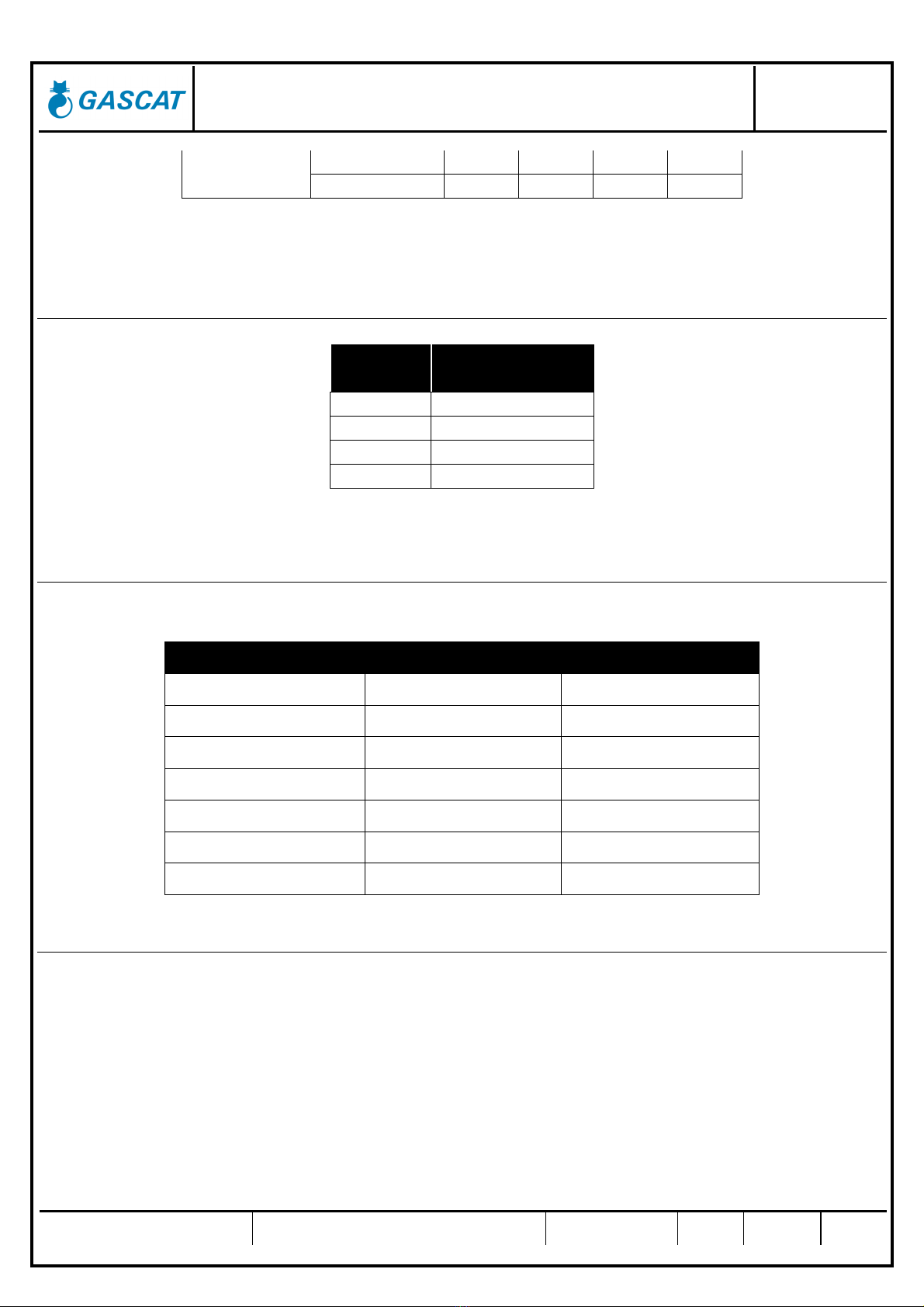
2.3.2 AVAILABLE CONNECTIONS
ND CONNECTIONS
3/4" NPT-F according to ANSI B2.1 or BSP DIN ISSO
228
1” NPT-F according to ANSI B2.1, BSP DIN ISSO 228
or FLANGE 150#RF AS E B16.5
2.3.3 TEMPERATURE LIMITS
Installation, Operation and Maintenance Manual
Pressure Regulating Valve – Model Ares N
MI–42
Prepared by Verified by Approved by CSQ Date Revision Page
José Junior Vanízio Lizo Jamerson 24/03/17
02 5 of 21
Operation temperature: -20°C to 60°C
Room temperature: -20°C to 60°C
The temperature limits given in this manual or in any applicable standard shall not be exceeded under any
circumstances, under risk of damage to the equipment, to the installation safety, and to the people involved in the
operation.
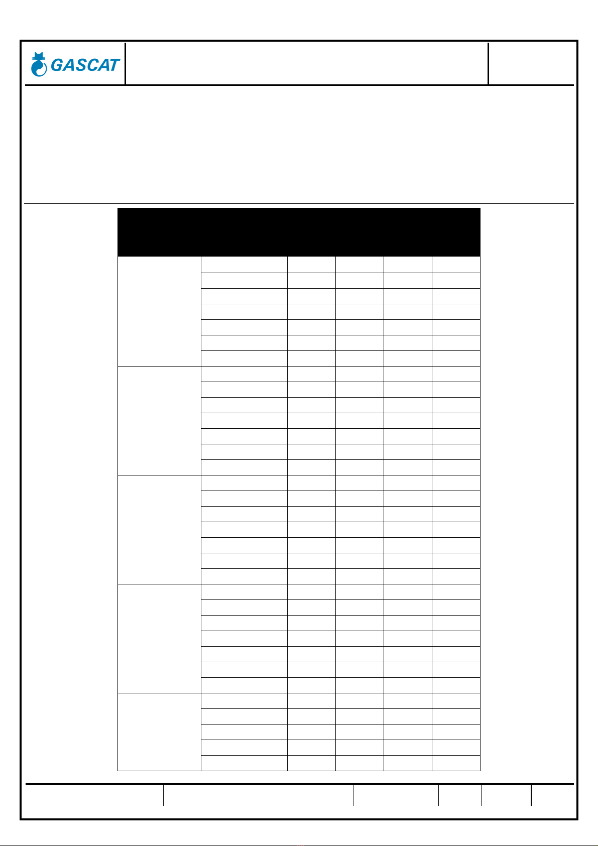
2.3.4 FLOW RATE TABLES
Natural Gas (Nm³/h)
Outlet Pressure
(mbar)
Inlet Pressure
(mbar)
Seat ND (mm)
4 6 8 10
20
0.5 10 21 28 31
1 16 30 49 58
2 31 63 61 64
3 44 63 64 -
4 48 64 - -
6 48 64 - -
8 58 - - -
35
0.5 10 20 26 60
1 16 28 47 55
2 30 60 60 62
3 42 61 64 -
4 46 62 - -
6 46 63 - -
8 56 - - -
50
0.5 10 19 24 30
1 16 27 42 52
2 30 56
60 62
3 41 60 62
-
4 47 61
- -
6 45 63
- -
8 60
- - -
100
0.5 9 18
23 29
1 16 26
36 49
2 30 53
61 62
3 40 66
70 -
4 46 71
- -
6 60 70
- -
8 71
- - -
200
0.5 9 14
23 26
1 14 20
31 40
2 20 45
53 63
3 30 59
70 -
4 39 60
- -
Installation, Operation and Maintenance Manual
Pressure Regulating Valve – Model Ares N
MI–42
Prepared by Verified by Approved by CSQ Date Revision Page
José Junior Vanízio Lizo Jamerson 24/03/17
02 6 of 21
6 49 66
- -
8 61
- - -
NOTE:
1) Informed capacity based on a 20% drop.
2) GN fluid. Density 0.6 KG/m³.
3) Informed pressures in bar and flow rate in m³/h @ 1atm 20ºC.
2.3.5 MAXIMUM WOR PRESSURE
ORI ICE
(mm)
MAXIMUM
PRESSURE (bar)
4 8
6 6
8 3
10 2
The pressure limits given in this manual or in any applicable standard shall not be exceeded under any circumstances,
under risk of damage to the equipment, to the installation safety, and to people involved in the operation.
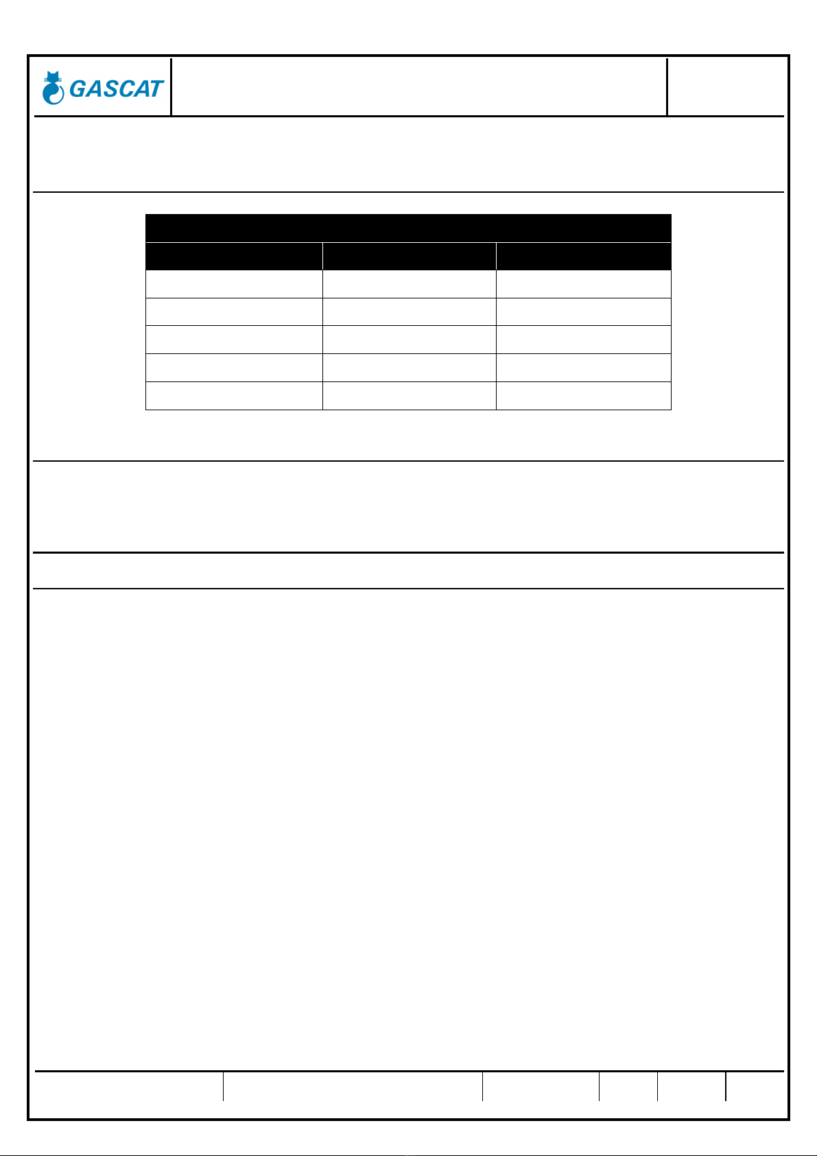
2.3.6 SET POINT PRESSURES - ARES N
The table below presents the adjustment ranges:
SPRING COLOR CODE SETTING RANGE (mbar)
BROWN / ORANGE 01.52.08 5.0 – 15.0
GREY 01.52.07 12.0 - 30.0
ZINCATED 01.52.09 22.0 - 35.0
ORANGE / GREY 01.52.10 30.0 - 75.0
YELLOW 01.52.11 70.0 - 100.0
BROWN 01.52.12 90.0 – 150.0
BLACK 01.52.13 105.0 – 240.0
2.3.7 ACCURACY AND LOC UP
Accuracy; Lock-up: AC up to 20%; SG up to 20%
Installation, Operation and Maintenance Manual
Pressure Regulating Valve – Model Ares N
MI–42
Prepared by Verified by Approved by CSQ Date Revision Page
José Junior Vanízio Lizo Jamerson 24/03/17
02 7 of 21
2.3.8 SET POINT PRESSURES – SSV G-10
SSV – G10
SPRING COLOR CODE SETTING RANGE (mbar)
RED 01.52.15 10 – 40
YELLOW 01.52.16 25 – 70
BROWN 01.51.88P 50 – 120
BLUE 01.51.89P 80 – 280
WHITE 01.51.90P 220 – 600
2.3.9 ACCURACY SSV
Accuracy: AG up to 10% according DIN EN 14382
3.0 - OPERATION PRINCIPLE
3.1 ARES N REGULATOR – BASIC INSTALLATION
The pressure regulator series ARES N works by principle of direct spring action against sensor element of outlet
pressure (diaphragm). The consumption variation and consequently change of pressure in the sensor element
(diaphragm) will change diaphragm position and diaphragm lever that acts the shutter shaft, increasing or decreasing the
valve passage in order to keep the outlet pressure constant.
In case of flow absence, the consequently outlet pressure increase is transmitted to the diaphragm resulting in this
upward movement; it will change lever position and shaft that will decrease the gas passage.
With gas consumption the opposite will happen and will open the main valve.

Installation, Operation and Maintenance Manual
Pressure Regulating Valve – Model Ares N
MI–42
Prepared by Verified by Approved by CSQ Date Revision Page
José Junior Vanízio Lizo Jamerson 24/03/17
02 8 of 21
ARES N

Installation, Operation and Maintenance Manual
Pressure Regulating Valve – Model Ares N
MI–42
Prepared by Verified by Approved by CSQ Date Revision Page
José Junior Vanízio Lizo Jamerson 24/03/17
02 9 of 21
3.1 EMBEDED BLOC ING VALVE – MODEL G-10
Optionally, the pressure regulator can be provided with a built-in shut-off valve for overpressure, limited to 600 mbar. This
is the model ARES N G-10.
The shutoff valve consists of an actuator with coupling by a ball collar (1) that monitors the output pressure. If the operating
pressure increasing beyond the set limit, the bushing outside the ball coupling (2) is displaced, this allows movement of the
central steam (3), which will presses the shutter (4) against the seat, freeing the locking system, and interrupting the gas
flow. After restoration of the normal working conditions, it is necessary to manually reset the valve.
4.0 - INSTALLATION
4.1 FILTER
We recommend the installation of a cartridge type filter, with 5 micra filtration degree, as close to the regulator inlet as
possible, without being joined flange to flange, because the filter installed immediately upstream of the regulator may
produce turbulence and cause disturbance in the pressure control of the regulator. Care in filter installation is essential for
the regulator proper operation, as any existing particles in the pipe may take lodge between the seat and the shutter,
damaging them and causing feedthrough.
4.2 CLEANING
Check the pipe cleaning before valve installation. We advise a complete purge of the line with nitrogen or compressed air.
4.3 FLOW DIRECTION AND SYSTEM INTEGRITY
Before starting the equipment installation, it is necessary to check if:
1) The equipment is in perfect conditions, or it has evidence of damage during transportation. If so, do not proceed
with the installation and contact GASCAT.
2) The space provided for access and installation of the equipment is adequate for future maintenance.
3) The installation is designed to support the load applied by the equipment.
4) The inlet and outlet connections, where the pressure regulator shall be installed, are perfectly aligned.

Installation, Operation and Maintenance Manual
Pressure Regulating Valve – Model Ares N
MI–42
Prepared by Verified by Approved by CSQ Date Revision Page
José Junior Vanízio Lizo Jamerson 24/03/17
02 10 of 21
5) All necessary pressure-sensing pick-ups, downstream of the equipment pipeline, were provided respecting the
dimensions recommended by the manufacturer.
6) A pressure gauge, or any other pressure-measuring device, was foreseen for the upstream and downstream of the
equipment to allow for the correct setting up at the operation start-up.
7) A vent line was planned between the regulator and the first outlet shut-off valve to assist the operator during start-up.
8) Check the flow direction marked on the body of the pressure-regulating valve and pay attention at the time of its
installation so that it is properly positioned.
Installation, Operation and Maintenance Manual
Pressure Regulating Valve – Model Ares N
MI–42
Prepared by Verified by Approved by CSQ Date Revision Page
José Junior Vanízio Lizo Jamerson 24/03/17
02 11 of 21
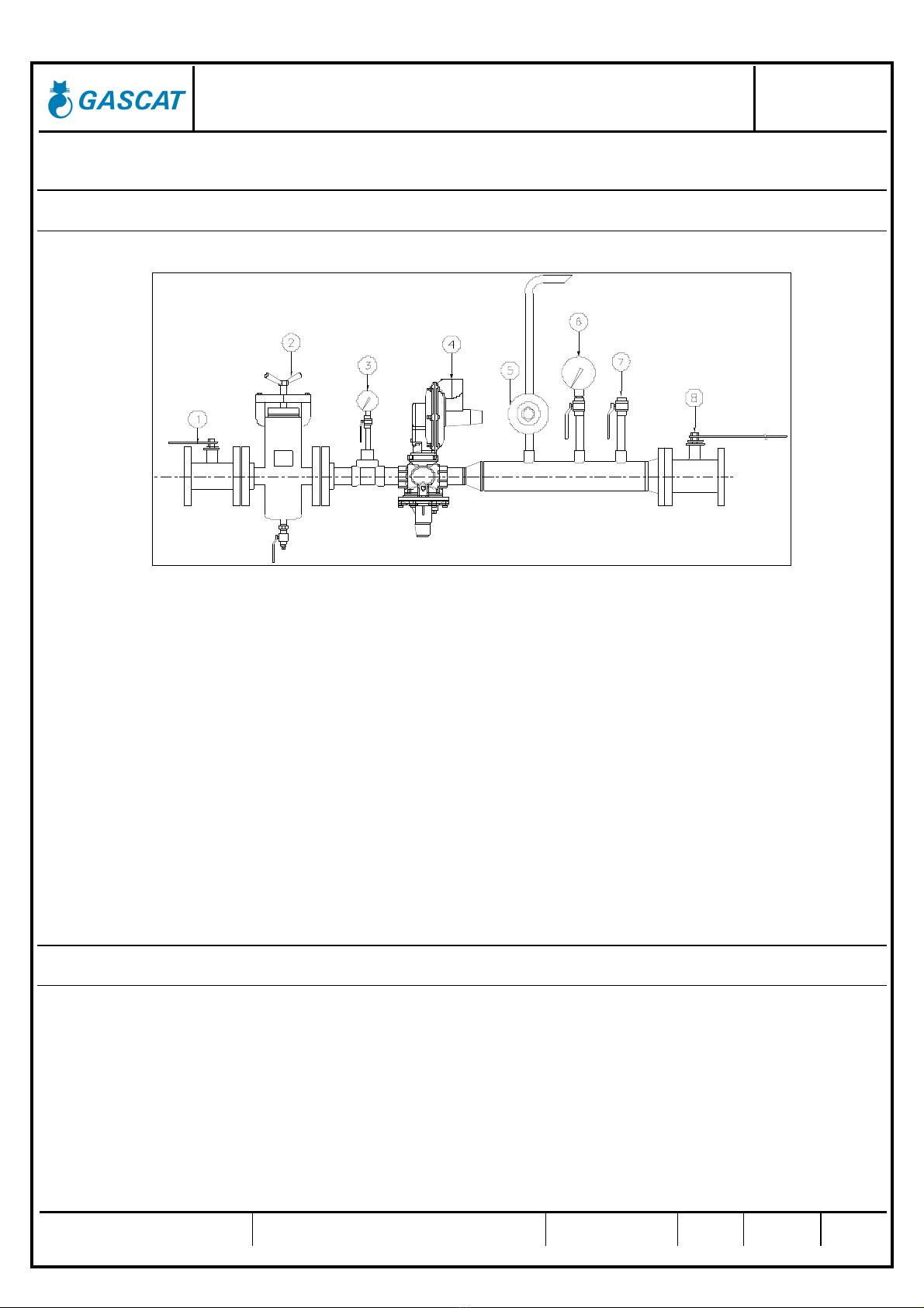
4.4 RECOMMENDED INSTALLATION SCHEME
4.4.1 SINGLE REGULATOR
1 – anual ball type blocking valve (or similar);
2 – Cartridge or basket type filter, model etrius (or similar)
3 – Pressure gauge for inlet pressure reading;
4 – Pressure regulator with built-in shut-off valve for overpressure, ARES N + SSV model G10
5 – Partial pressure relief valve model JR LP
6 – Pressure gauge for outlet pressure reading
7 – Purge Valve
7 – anual ball type blocking valve (or similar)
4.5 COMMISSIONING AND START-UP
4.5.1 GENERAL RECOMMENDATIONS
Always, before proceeding with the equipment commissioning it is important to:
1) Check if the equipment is properly installed according to the recommendations of item 4.3 of this manual.
2) Shut the blocking valves of the inlet, output and bypass (if applicable)
3) Open vent valve downstream of the last pressure regulator installed on the span.
4) ake sure that the station is depressurized.
Installation, Operation and Maintenance Manual
Pressure Regulating Valve – Model Ares N
MI–42
Prepared by Verified by Approved by CSQ Date Revision Page
José Junior Vanízio Lizo Jamerson 24/03/17
02 12 of 21
5) Check if all connectors are properly secured in the station before starting pressurization of the span.
6) Check if the installed equipment has suitable operating conditions, using the information available on the
nameplate attached to the equipment.
7) ake sure that the SSV is in the shut position.
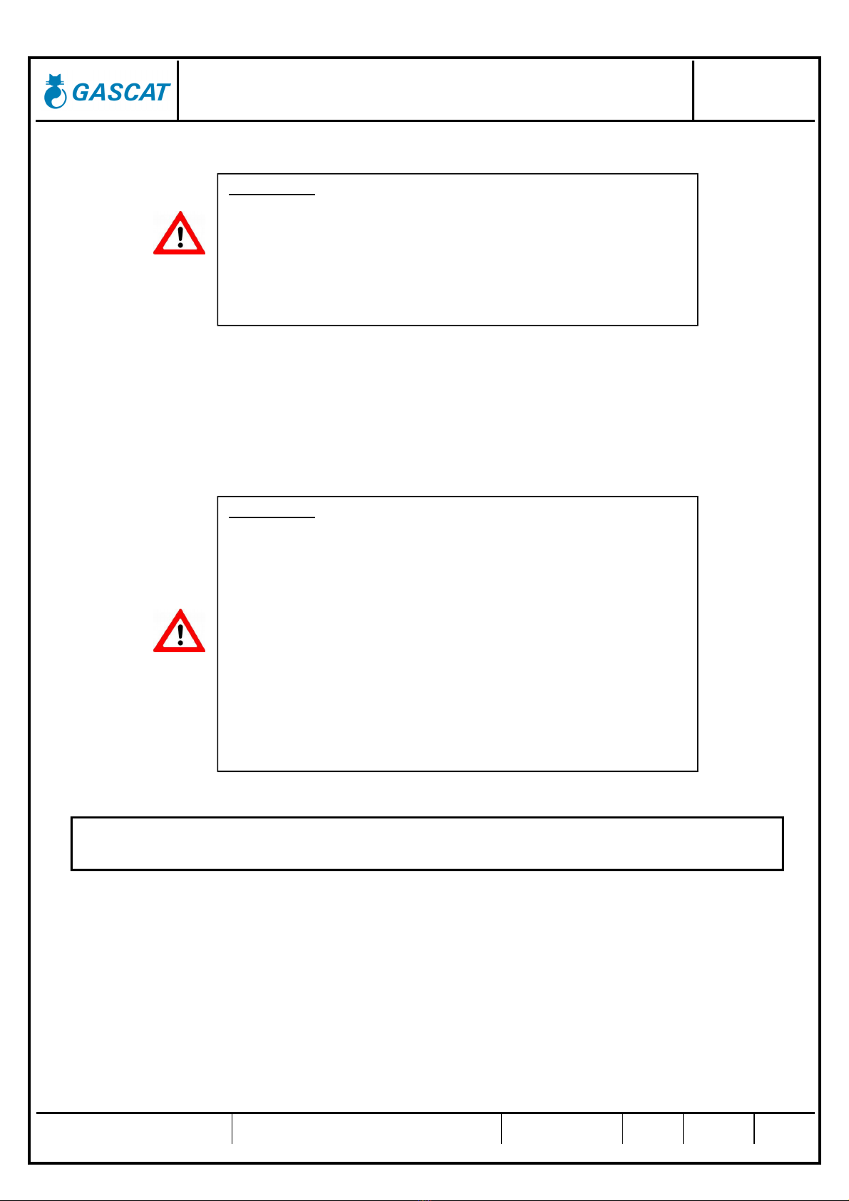
AT
TENTION
:
* Under no circumstances proceed with pressurization of the span where
the equipment is installed by the downstream valve of the equipment.
* Under no circumstances proceed with the depressurization of the span
where the equipment is installed by the valve located upstream of the
equipment, such as the filter drain.
ATTENTION
:
GASCAT’s SSV are sent to the field already calibrated, however,
depending on transport conditions and the equipment handling the valve
may have its set point changed.
Therefore, we recommend that you check the SSV set point with the
help of an external air supply directly connected to the actuator, before
proceeding with the pressurization of the span.
odel ARES N valves are not sent to the field with adjusted set points;
this measure tends to preserve the life of the equipment internals.
Therefore, after receiving a pressure regulator valve model ARES N
remember that you must perform the set point adjustment before putting
the equipment into operation.
The pressure red
ucing station setting shall be in accordance with the DIN EN 12186 / NBR 12712
standards and all other regulations in force in the region where it will operate.
Installation, Operation and Maintenance Manual
Pressure Regulating Valve – Model Ares N
MI–42
Prepared by Verified by Approved by CSQ Date Revision Page
José Junior Vanízio Lizo Jamerson 24/03/17
02 13 of 21
4.5.2 COMMISSIONING (SINGLE REGULATOR SPAN)
Using, as a reference, the assembly scheme presented in item 4.5.1, proceed to the description on commissioning the
regulator model Ares N in a span of simple regulation, considering that the recommendations made in section 4.6.1 of this
manual have been properly observed.
1) Shut-off the vent valve.
As the line shut-off valves are closed, we will use the vent valve to simulate a small flow and so proceed with the
regulator adjustment before aligning the span.
2) Check if the regulator regulating spring is properly relieved (discharged).
Alleviating the regulating spring, we are ensuring that the valve will only admit a small pressure downstream of the
regulator, enough to pass the same to the closed position.
3) Press completely the regulation spring of the shut-off valve incorporated in model G-10 to ensure that the same
is in the high pressure trip position at the commissioning start. Reset the shutoff valve if it is disarmed.
4) SLOW AND GRADUAL open the inlet shut-off valve, or when the station is provided with a by-pass of the shut-
off valve use the same to perform pressurization.
5) In following, we will make the set point adjustment of the SSV model G-10. With a combined spanner wrench
13/16" turn the setscrew of the pressure regulator valve ARES N clockwise, to gradually raise the output
pressure to the desired set point for the SSV.
6) Slowly remove the load of the G-10 blocking valve regulating spring until the valve operates blocking the line.
7) Repeat steps 5 and 6 three times to verify the blocking repeatability and perform the fine-tune adjustment.
8) Once the shut-off is adjusted, perform the adjustment of the pressure regulator model ARES N, with the vent
valve and the shut-off valve of the main line still closed, by increasing the pressure to the desired set point for the
pressure regulator. However, as this is a static pressure adjustment, i.e., with no flow, we are actually adjusting
the regulator lock-up pressure, then proceed by raising the pressure to a value 20% higher than the desired
pressure for the set point under load, for cases in which shutting with 20% is desired.
Example: Desired set point: 0.35 – Shut-off adjustment: 0.35/0.8 = 0.43 bar
9) Slowly open the vent valve until the pressure reaches the desired set point.
10) Close the vent valve slowly and check the shutting pressure.
11) Repeat steps 9 and 10 three times to verify the shutting repeatability and, if necessary, perform the set-up fine-
tuning.
12) Check for leaks in connectors and other pressure regulator connections of the span.
13) Once the shut-off valve and the regulator are set, proceed with the alignment of the span by SLOW AND
GRADUAL opening of the outlet shutoff valve.
14) Note the accuracy of the set pressure, if the output pressure reaches a value below the adjusted pressure with
the outlet shutoff valve closed, probably the consumption (flow rate) is larger than the regulator capacity, in this
case it is necessary to check the equipment sizing, or if the operating conditions informed for design are
respected.
Installation, Operation and Maintenance Manual
Pressure Regulating Valve – Model Ares N
MI–42
Prepared by Verified by Approved by CSQ Date Revision Page
José Junior Vanízio Lizo Jamerson 24/03/17
02 14 of 21
15) If the scenario is as above, we do not recommend to increased the load on spring of the pressure regulator in
order to achieve the desired output pressure, because in this case the shutting pressure will change to a higher
value, which may coincide with the set points of other devices of the line.
4.5.3 THE BAC -UP LINE SET-UP
When the regulator is installed in a back-up line, we recommend that the procedure given in 4.6.2 be repeated, but
this pressure regulator setpoint should be adjusted for a pressure 15% - 20% lower than the set point of the valve
in operation.
After doing so, open SLOW AND GRADUALLY the outlet shut-off valve so that the downstream pressure of the
back-up span regulator equalizes with the pressure already in operation. The back-up regulator will remain shut.
To make the regulator of the reserve span assume regulation, slowly press the regulation spring clockwise until
the set point of the regulator reaches a value higher than the set point of the line in operation, thus the reserve
regulator will open slowly and assume operation.
It is important that the two regulators remain with a set point difference of at least 5% - 10%, so that there is no set
point overlap causing a competition between the two lines, i.e., at one instant one regulator opens, at another
instant the reserve regulator opens, promoting inaccuracy in regulation.
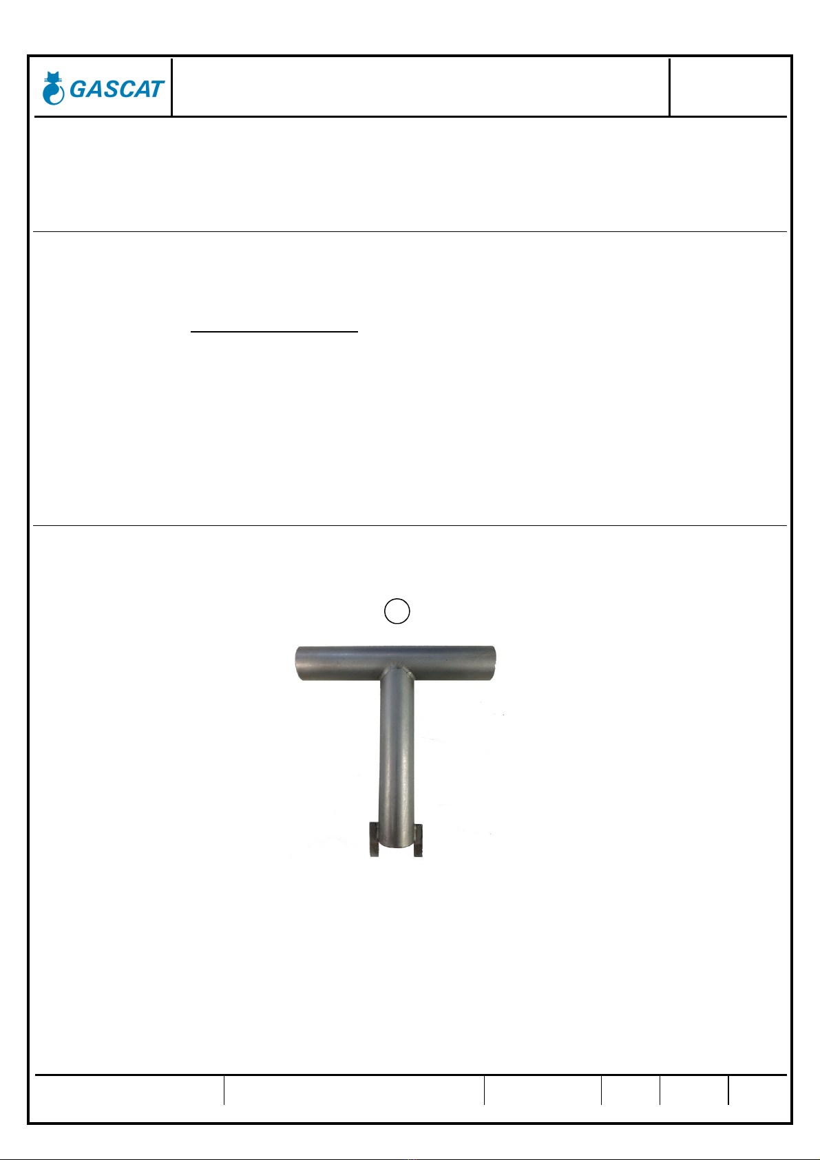
4.5.4 LIST OF RECOMMENDED TOOLS
To carry out commissioning set point adjustments and start-up of the GASCAT’s regulators model ARES N it is
required only the use of a special tool for setting up the regulator and the SSV G10 adjustment springs.
1

Installation, Operation and Maintenance Manual
Pressure Regulating Valve – Model Ares N
MI–42
Prepared by Verified by Approved by CSQ Date Revision Page
José Junior Vanízio Lizo Jamerson 24/03/17
02 15 of 21
5.0 TROUBLE SHOOTING
This section of the manual aims to evidence eventual troubles that may occur in the field to their causes.
The problems listed in this section may derive from different situations, but most of them are related to the gas
conditions (impurities), natural wear, and fault during the equipment operation.
It is important to keep in mind that the operation and maintenance of GASCAT equipment should only be
performed by highly skilled and trained personnel, preferably by teams trained by GASCAT’s instructors.
For training and qualification of operators and technicians, please, contact GASCAT through the e-mails below, to
check on their availability.
PROBLEM PROBABLE CAUSE CORRECTIVE MEASURES
Outlet pressure decreasing
Saturated filter element
Insufficient flow
Check the filter and clean the filter
element
Outlet pressure increasing
Direct Gas passage through the
valve
Presence of particles
between seat and shutter
Release the screws of intermediary
body and remove the regulator of
the body valve.
Check shutter and seat.
Clean or change the parts.
Gas passage through the vent
Diaphragm rupture or
presence of particles in
the relief set
Release slowly the regulating screw
and remove the spring.
Release the cover screws, remove
the diaphragm and clean or change
it.
Slam shut valve blocking
Outlet pressure gradual
increasing
Direct gas passage
through the valve
Check the slam shut seat; change
it. Fix the seat in the body, remove
the excess of grase.
Check shaft o'rings and change it if
necessary
Check the slam valve shutter and
change it if necessary
6.0 MAINTENANCE
It is essential to perform preventive maintenance of pressure regulators' model URANO for proper operation of the
equipment over time, and it is directly related to the reliability of the pressure control system, avoiding operating problems
to the user.
The frequency of maintenance varies considerably according to the installation, operating conditions and the quality
of the fluid in question, for example, if the equipment is subject to a large presence of contaminants such as black
powder, yellow powder, oil, condensate, etc. certainly the service intervals should be shorter.

Installation, Operation and Maintenance Manual
Pressure Regulating Valve – Model Ares N
MI–42
Prepared by Verified by Approved by CSQ Date Revision Page
José Junior Vanízio Lizo Jamerson 24/03/17
02 16 of 21
GASCAT has standard repair kits for each component of the pressure regulator model URANO containing the most
likely items to wear with time; this list of components is given in this manual for users guiding.
Before starting maintenance of GASCAT’s pressure regulators, you shall always assure yourself to have a
replacement kit with original GASCAT parts, as well as this instruction manual for reference of how to work safely and
efficiently during the equipment maintenance.
ATTENTION
:
GASCAT’s pressure regulator valves components are developed,
manufactured and tested exclusively by GASCAT to provide the highest
efficiency and safety of operation. Non-using GASCAT’s original
components make the operation unsafe and compromise the process
efficiency.
GASCAT takes no responsibility for the operation of equipment using
non-original components.
Installation, Operation and Maintenance Manual
Pressure Regulating Valve – Model Ares N
MI–42
Prepared by Verified by Approved by CSQ Date Revision Page
José Junior Vanízio Lizo Jamerson 24/03/17
02 17 of 21
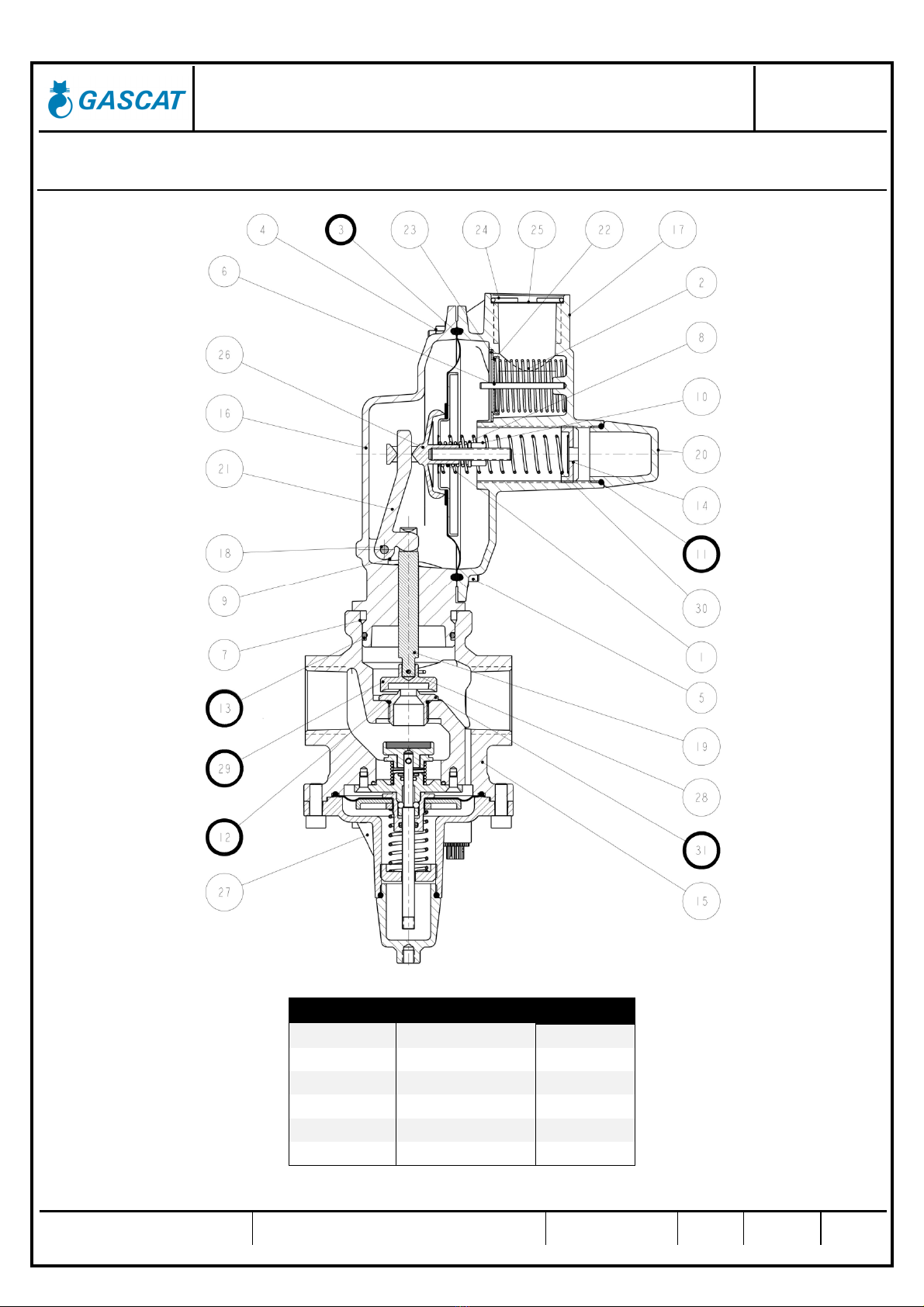
6.1 RECOMMENDED REPAIR PARTS AND ITS
ARES N + SSV
POS. DESCRIPTION QUANTITY
3 DIAPHRAG 1
11 O'RING 1
12 O'RING 1
13 O'RING 1
29 SHUTTER 1
31 SEAT 1

Installation, Operation and Maintenance Manual
Pressure Regulating Valve – Model Ares N
MI–42
Prepared by Verified by Approved by CSQ Date Revision Page
José Junior Vanízio Lizo Jamerson 24/03/17
02 18 of 21
SSV G-10
POS. DESCRIPTION
QUANTITY
3 DIAPHRAG 1
9 O'RING 1
10 O'RING 1
11 O'RING 1
12 O'RING 1
14 PLATE 1
17 VENT PLUG 1
22 SHUTTER 1

Installation, Operation and Maintenance Manual
Pressure Regulating Valve – Model Ares N
MI–42
Prepared by Verified by Approved by CSQ Date Revision Page
José Junior Vanízio Lizo Jamerson 24/03/17
02 19 of 21
6.2 PROCEDURE FOR ARES N REGULATOR DISASSEMBLY
1) Before proceeding with the equipment disassembly, check if all the conditions set out in item 4.6.1 of this
manual have been observed.
2) Under no circumstances start the equipment disassembly if it is pressurized.
The disassembly procedure given below refers to the components’ positions shown in the diagram of section 6.0
of this manual.
3) Remove all connectors connected to the main valve.
4) Proceed by removing the Viewfinder (pos 20) and wtith a tool, remove the Spring Adjuster (pos 14).
Note: In an eventual change in the working conditions, only with the 4th step of this procedure, it is necessary
to change the Regulator Spring to a spring that reaches the desired set.
5) Proceed by removing the screws (pos 7), and it is now possible to remove/change the Seat (pos 31) with a
tool

Installation, Operation and Maintenance Manual
Pressure Regulating Valve – Model Ares N
MI–42
Prepared by Verified by Approved by CSQ Date Revision Page
José Junior Vanízio Lizo Jamerson 24/03/17
02 20 of 21
6) Remove the Top Cover screws (pos 5) and the Top Cover (pos 17 )of the actuator.
6.3 PROCEDURE FOR SSV G-10 DISASSEMBLY
1) Proceed by removing the Viewfinder (pos 20) and wtith a tool, remove the Spring Adjuster (pos 15).
Note: In an eventual change in the working conditions, only with the 4th step of this procedure, it is necessary
to change the Regulator Spring to a spring that reaches the desired set.
Shutter
(pos 29)
Table of contents
Other Gascat Control Unit manuals


Popular Control Unit manuals by other brands


SEA
SEA 9521 Hardware manual

UTEPO
UTEPO SFP-1.25G-550M quick start guide

Microchip Technology
Microchip Technology BM78SPP05MC2-0001AA manual

VAN DER ENDE
VAN DER ENDE Envalve VK Series installation manual

Yamatake
Yamatake ACTIVAL VY51XXJ instructions

STIEBEL ELTRON
STIEBEL ELTRON HUV 1 Operating and installation


