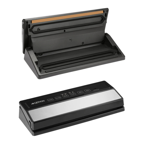
GGM gastro GGM24 User manual

1
GGM GASTRO
CHAMBER VACUUM
PACKAGING MACHINE
GGM24
GGM32
GGM42
GGM52
USE AND MAINTENANCE MANUAL
ORIGINAL INSTRUCTIONS

2
Warning!
This appliance is not suitable to be used by people (children included) with reduced
physical or mental capabilities or with lack of experience and knowledge,
otherwise they have been instructed by someone responsible of their safety.
Children must be controlled in order they do not play with the appliance.
DANGER - WARNING!
The sealing bar may reach high temperatures during and after the usage process.
It is recommended to watch out and avoid direct contact until the cooling process is over.
DANGER –WARNING!
The machine is to be used in inner environments.
DANGER - WARNING!
The device cannot be opened by the end user.
Should the power wire be damaged,
or should there be any electric repairs, they must be replaced by
the manufacturer, or by authorized personnel only, in order to avoid any risk.
THE MACHINE IS SUPPLIED WITH GROUND PROTECTION WIRE.
The ground protection system is identified by the proper symbol.

3
CHAPTER 1
IDENTIFICATION OF THE “USER
MANUAL”
The instructions handbook is a document issued by
the manufacturing company and is an integral part
of the machine. This document is adequately
identified for easy tracing and/or subsequent
references.
All rights relating to the reproduction and disclosure
of the information contained in this handbook and
the documentation quoted and/or attached are
reserved.
Aim of the document
This handbook contains the information necessary to
the customer and assigned personnel for the correct
installation, use and maintenance of the machine at
good conditions and at maximum safety.
Safety precautions and manufacturer’s
responsibility limits.
Every operator-machine interaction relating to the
intended use of the machine and its overall life cycle
has been carefully and thoroughly analysed by the
manufacturing company during the design phase,
construction phase and the drafting of the
instructions handbook.
It is nevertheless understood that experience,
adequate training and “common sense” of the
personnel operating on the machine are of primary
importance. These requirements are therefore
considered indispensable during all machine
operating phases and consultation of this handbook.
The non-observance of the safety precautions or
specific warnings indicated in this handbook, the use
of the machine by unauthorized personnel, violate all
safety standards regarding the design, construction,
and intended use of the machine and relieve the
manufacturer from every liability in the case of
damage to persons or property.
The manufacturing company is therefore in no way
responsible for the non-observance on the part of
the user of the safety precautions listed in this
handbook.
Regulatory references
The following definitions are used according
to:
-Attachment “I” to the directive 89/392/CEE and
subsequent issues;
-“Machines Directive” 2006/42/CE replacing
98/37/CE.
Waste of the machine after its usage cycle
Electric and electronic appliances contain dangerous
substances with effects potentially harmful for health
people and environment. It is recommended to
waste it properly, it means in the authorized garbage
dump.

4
CHAPTER 2
HOW TO CONSULT AND USE THE
INSTRUCTIONS HANDBOOK
This document is an integral part of the machine.
Preserve a copy of this instructions handbook for the
entire working life of the machine even if transferred
or sold to third parties. Requests for further copies
of this document must be made by means of
purchase order addressed to the manufacturing
company.
To maintain the instructions handbook in good
conditions:
-Use the instructions handbook taking care not to
damage its contents. In particular, do not leave
the instructions handbook around during use
and remember to return it to its proper place
immediately after consultation.
-Do not remove, rip out or rewrite parts of the
instructions handbook. Any changes required
must be referred to and subsequently supplied
by the manufacturing company.
-Keep the instructions handbook in a safe place,
away from damp, heat and other environmental
elements which could damage it.
Definitions
The following definitions are used according
to the “Machine Directive” CEE 89/392 and
subsequent issues:
-Operator: person or persons assigned to
machine operation, adjustment, routine
maintenance or cleaning
-User: body or person responsible for and/or
owner of the machine.
Machine manufacturer identification data and
positioning of the “CE MARKING” plate.
Identification of the manufacturing company as
producer of the machine takes place in accordance
with the legislation in force by means of the
following documents:
-Declaration of conformity;
-(CE marking;)
-Instructions Handbook
-A special plate applied to the machine is
marked permanently with the following data
concerning CE MARKING.
CHAPTER 3
WARRANTY
The manufacturing company engages, for 12
(twelve) months from the date of shipment and
direct delivery of the goods, to assure the customer
or concessionaire the integrity and the good working
of the components regarding the above mentioned
machine.
All machine components normally subject to wear,
that is to say components in which use causes a
constant wear and tear, are not included in the
warranty:
1. Electrical resistances –Teflon –Rubber gaskets
–Chamber opening pistons –Sealing
diaphragms –Air filters –Oil filters –Oil change
–Pump blades
2. If the vacuum pump of a machine under
warranty is sent to the manufacturing company
because of aspiration problems and malfunction,
the manufacturing company has the right to
check whether any foreign bodies have been
aspirated (liquids, solids, sauces, etc..). If this
should be the case, the repair (materials and the
labour) will be duly charged, since the problem
is not due to manufacturing defects, but to
customer negligence during use.
3. Possible problems linked to the electronic panel
cards of the circuit will have to be examined by
the manufacturing company before sending the
part which has to be replaced under warranty. A
sudden change in voltage, an electrical
overfeeding, a disturbance in the external
current network, could cause damages which
are not to be attributed to the manufacturing
company.
4. Possible problems with pneumatic, structural,
mechanical parts will be duly solved as per
warranty terms without any charge.

5
5. During the warranty period, for interventions
under warranty, the replaced materials will not
be charged, while the labour will be duly
charged. During the warranty period, for
interventions not included in the warranty for
various reasons, both the materials replaced and
the labour will be duly charged.
6. During the warranty period, should any external
intervention of our technicians be requested, the
travel costs (to and from) will be fully charged
independently of the reason behind the
intervention.
7. Any interventions on the machines are to be
carried out at the manufacturer’s premises both
during the warranty period and after the
warranty period; we point out that no transport
costs (to and/or from) will be refunded.
8. The transport for any materials sent to the
manufacturing company, both during the
warranty period and after the warranty period,
must compulsorily take place in ex works.
9. Any materials sent to the manufacturing
company with transport charges will be
automatically refused.
10. Any components considered defective (pump,
electronic panel card, etc..) and mishandled by
the customer during the warranty period will
not be considered under warranty. The
manufacturing company has the task of carrying
out this function in a strict manner.
Do not remove the CE MARKING plate and/or
replace it with a different one. Should the CE
MARKING plate be accidentally damaged,
detached from the machine or the
manufacturer’s seal removed, the customer
must compulsorily and immediately inform
the manufacturing company.
The plate is placed on the external side of the
machine
User obligations
The user must inform the manufacturing company
immediately of any safety system defect and/or
malfunction and of any presumed danger
encountered. It is strictly forbidden to the user
and/or third parties (excluding duly authorized
personnel of the manufacturing company) to make
modifications of any kind or extent to the machine
and its functions or to this technical publication. In
case of malfunctions or danger due to the non-
observance of the above, the manufacturing
company cannot be held responsible for the
consequences. It is advisable to request any
modifications directly to the manufacturing
company.
CHAPTER 4
GENERAL SAFETY PRECAUTIONS
It is recommended to comply strictly with the
following safety precautions:
1. never touch the metal parts of the machine with
wet or damp hands;
2. do not pull the supply cable or the machine itself
to disconnect the plug from the current outlet
(ref. page 1);
3. children or unqualified personnel are not allowed
to use the machine without supervision;
4. electrical safety of the machine is ensured by its
correct connection to an effective earthing as in
accordance with the electrical safety standards
in force; it is necessary to check this
fundamental requirement and, if in doubt, ask
for a thorough check by professionally qualified
personnel. The manufacturing company cannot
be held responsible for possible damages caused
by the lack of a plant earthing;
5. in the case of a possible damage to the safety
earthing, disconnect the machine in order to
prevent its activation;
6. Always use safety fuses comply with the
safety standards in force , the correct value
and with suitable mechanical properties ;
7. avoid the use of repaired fuses and the
creation of short circuit between the
terminals present on the fuse holder
8. the user of the machine must not replace its
supply cable; in the case the supply cable is
damaged or needs replacing, refer only to the
manufacturing company of the machine for its
replacement;
9. keep the cable away from hot parts;
10. always switch off and disconnect the machine
from the power supply before beginning any
general cleaning or washing operation;

6
11. clean machine coating, panels and controls
using soft and dry cloths, or cloths slightly
soaked in mild alcohol or detergent solution.
Obligations in the case of malfunction and/or
potential danger
Operators are obliged to signal any deficiency and/or
potentially dangerous situation immediately to a
direct superior..
CHAPTER 5
INSTALLATION
Remove the packaging and check that the machine
is undamaged. In particular, look for any possible
damages caused by transport. If in doubt, do not
use the machine and refer to the manufacturing
company.
Place
Position the machine horizontally in a place with low
humidity percentage and far from heat sources.
Do not install the machine in an explosive
atmosphere.
Disconnect the power supply plug before
starting any checking operation which may
require parts.
Controls and inspections
Before starting the machine, check the oil level
through the sight glass located on the motor/pump.
(Fig. 5.1). In order to access the pump, unscrew
the back panel of the machine and remove it.
Image 5.1. Pump oil level indicators
Before connecting the vacuum packaging
machine, make sure that the plate data
corresponds whith the supply mains data UL.
After level checking and casing re-installation,
connect the plug to a current outlet. If it is not
possible to connect the plug and the outlet, the
outlet must be replaced with the correct one by
professionally qualified personnel who should also
check that the outlet cable section is correct for
machine power consumption.
It is not advisable to use adapters, multiple outlets
and/or extensions. If this should be the case, use
only simple or multiple adapters and extensions in
accordance with the safety standards in force. Do
not exceed current capacity limit and maximum
power level marked on the multiple adapter.
Particular warnings
1. It is recommended to reset the machine after
every usage.
2. When using a tri-phase power supply, pay
attention to the motor rotation direction
indicated by an adhesive label (fig. 5.2). Should
the rotation be on the opposite direction (a loud
metal noise will be heard out and the chamber
won’t get closed), invert two of the three supply
wires on the plug.
3. By a standard usage of the machine, no
particular cleaning operation of the chamber
machine is required. Should it be needed (i.e.
bags inner product pours out of the bag), it is
recommended to use a rag soaked with alchool.
Image 5.2. Adhesive labels indicating the rotation
direction.

7
The earthing (yellow-green) must not be
moved or disconnected. In the case of power
3P + N ie in the presence of the neutral wire
(blue) must not be moved or dissected.
Before cleaning the machine, disconnect the
plug.
CHAPTER 6
USAGE OF THE PACKAGING MACHINE
Vacuum packaging
1. Connect the bipolar plug, if 230 V, or the three-
pole plug, if 380 V, to the current outlet
2. Press the line main switch and the ON/OFF
button thus connecting the electric circuit which
supplies the modular card for the automatic
cycle phases.
3. Set the vacuum time (or percentage) required,
the sealing time and the gas injection time (if
the machine is equipped with such a system).
4. Position the bag (or bags) inside the vacuum
chamber; put the bag opening perfectly flat on
the sealing bar. Put the exceeding part of the
bag, if any, in the fissure between the chamber
and the sealing bar (image 6.1).
5. Two or three removable food polyethylene
shelves are positioned inside the vacuum
chamber to level the product thickness
according to the sealing bar. The polyethylene
shelves can be removed depending on necessity.
6. Lower the bell-lid and press adequately on it
until it remains closed, thus permitting the work
cycle to begin.
7. The different cycle phases are automatic and
after a time preset by the manufacturer the bell-
lid opens thus enabling the subsequent cycles to
begin.
Image 6.1. Bag correct placement inside the
chamber.
Vacuum-packaging with inert gas injection
OPTIONAL (ref. tab 1)
1. Set the work cycle with inert gas injection on the
control panel by pre-selecting the relative time.
2. Connect the hose coming from the gas cylinder
to the hose connection positioned on the
side/rear of the vacuum packaging machine by
means of the relevant clamp, then set the gas
cylinder gauge at a pressure value of 1 ATA.
3. Position the bag containing the product inside
the vacuum chamber, fitting the gas nozzle
inside the bag opening (image 6.2); make sure
that there are no folds obstructing the gas flow.
Image 6.2. Positioning of the bag with gas option
active.
Sacchetto

8
Vacuum packaging of liquid or semiliquid
products
By means of the chamber vacuum packaging
machines of our range it is possible to vacuum
package liquid or semi-liquid products (soups,
sauces, etc..) thus increasing their duration time and
keeping hygiene and taste unaltered.
1. Vacuum cycles are set as described in the
chapter Vacuum packaging.
2. The SOFT-VACUUM option allows the packaging
of liquid products.
3. All the vacuum packages can be stored in a
refrigerated cabin.
Tab 1. EXAMPLES OF PACKAGING WITH PROTECTIVE ATHMOSPHERE
PRODUCT
OXYGEN
% (O2)
CARBON DIOXYDE
% (CO2)
NITROGEN
% (N2)
Sliced salami
-
20
80
Roast meat
80
20
-
Beer/can drinks
-
100
Biscuits and oven products
-
100
100
Coffee
-
100
100
Fresh meat
70/80
30/20
-/-
De hydrated meat and spices
-
-
100
Minced meat
-
-
100
Chocolate
-
100
-
Fresh cheese / Mozzarella
-/-
20/-
80/100
Mature cheese / Cream / Butter /Margarine
-
-
100
Fresh salad / parsley
-
50
50
Yogurt / Puff pastry
-
100
-
Powdered milk
-
30
70
Baking powder
-
100
100
Apples
2
1
97
Sliced bacon
-
35
65
Sandwich loaf / Bread
-
100
-
French toast / Toasted bread
-
80
20
Pasta
-
-
100
Fresh pasta / tortellini / Lasagne
-
70/100
30
Potatoes / French fries / Snacks / Hop
-
0
100
Anchovies, sardines…
-
60
40
Fish
30
40
30
Pizza
-
30
70
Poultry
-
75
25
Tomatoes
4
4
92
Pre-cooked food
-
80
20
Sausages
-
20
80
Escalopes
70
20
10
Fruit juices
-
-
100
Trouts / Fish-breeding
-
100
-
Wine / Oil
-
-
100

9
For the packaging of food with protective athmosphere, ensure to be using food certified gases, not
explosive ones.
CHAPTER 7
OPERATION
7.1_VACUUM CYCLE DESCRIPTION
LCD DISPLAY
The cycle starts when you close the chamber (lid),
by activating the suction of the pump. VAC writing
will appear on the display together with the
countdown (in seconds) of vacuum time up to 0
(zero). Should the gas option be active, the GAS
writing will appear during the cycle, as it will be
injected inside the chamber. Afterward, sealing will
start as the SEAL writing appears on the display. At
the end of this process, the cooling of the resistance
starts, indicated by the COOLING writing. As it
disappears, the OPENING writing will appear on the
display and the lid will open automatically.
NOTE: Should it be needed to interrupt the cycle in
advance for any reason, press ON/OFF for 3
seconds. The machine automatically allows the air to
enter again and let the lid open.
During the normal vacuum cycle, press the button
“PUMP GASTRO“ for 3 seconds to seal in advance
and anticipate the process.
7.1.1_Control buttons_Version 220V
1. General switch O-I
2. LCD display
3. ON/OFF: to switch the electronic board on and
to anticipate the end of the cycle without
sealing.
4. SET: to set programs (vacuum, sealing and
gas).
5. + and -: to select the required program and to
increase or decrease the cycle parameters.
6. PUMP GASTRO: to activate the functions of
vacuum in GN trays, pump cleaning and heating
and manual sealing.
7. Vacuum gauge
8. Printer (OPTION)
9. Lighting button (indicating power electricity ON)
to replace printer thermopaper
10. Button for paper scrolling
7.1.2_Control buttons_version 380V
1. General switch O-I
2. LCD display
3. ON/OFF: to switch the electronic board on and
to anticipate the end of the cycle without sealing.
4. SET: to set programs (vacuum, sealing and
gas).
5. + and -: to select the required program and to
increase or decrease the cycle parameters.
6. PUMP GASTRO: to activate the functions of
vacuum in GN trays, pump cleaning and heating
and manual sealing.
7. Vacuum gauge
8. Printer (OPTION)
9. Lighting button (indicating power electricity
ON) to replace printer thermopaper
10. Button for paper rolling
11. Light for power ON
12. Bar selector
7.1.3_User setting menu
Switch on the machine before entering the user
setting menu (switch O-I or power light must be
enlighted), press contemporarily SET and ON/OFF
buttons for a few seconds. It will appear on the
display:
1. Language setting (Lang)

10
Use +and –buttons to choose the desired
language: English, Italian, Spanish, German and
French.
By pressing the SET button it is possible to
confirm and pass to the following option.
2. Vacuum sensor setting (Vac Type)
By using this option (VACUUM SENSOR), it is
possible to select the percentage of vacuum
desired within the chamber:
0: time in seconds
1: vacuum percentage
By pressing the SET button it is possible to
confirm and pass to the following option.
3. Display setting (Display)
It is possible to set the display mode (PRINTER
OPTION):
0: fixed: hour/date
1: intermittence: hour/date –machine setting
By pressing the SET button it is possible to
confirm and pass to the following option.
4. Time/date setting
It is possible to set time and date by using the
buttons + and –,by pressing the SET button,
the cursor passes to the following value (Time
is set in 24h format and date as DD/MM/YY i.e.
07th September 2013 appears as 07/09/13).
By pressing the SET button it is possible to
confirm and pass to the following option.
5. User name setting
It is possible to insert the user name by
following two methods:
- by pressing + and –buttons to choose
characters and then SET to pass to the
following option
- by using the keyboard (USB KEYBOARD
OPTION).
By pressing the SET button, it is possible to
pass over the empty positions and then confirm
the set parameters to close this menu.
Afterward the stand-by writing will appear.
7.1.4_Program setting
Switch the machine on by pressing the button
ON/OFF. It will appear appear the stand-by writing:
The number “ 1 ” indicates which program is being
used. By pushing the buttons + and –it is possible
to change to the following program ( 10 or 20
programs)
1. Vacuum time setting
By pressing the button SET for some seconds in
each program, it will appear:
By using the buttons + and –it is possible to
increase or decrease the seconds (between 0
and 50) of vacuum.
By pressing the button SET it is possible to
confirm or to switch to the following option.
2. Vacuum percentage setting
(VACUUM SENSOR OPTION)
By pressing the button SET for some seconds in
each program, it will appear:
By using the buttons + and –it is possible to
increase or decrease the seconds (between 0
and 99) of vacuum.
By pressing the button SET it is possible to
confirm or to switch to the following option.
3. Pump intermittence setting (liquids and creams)
(SOFT VACUUM OPTION 20 programms)
This option allows the pump intermittance
working to vacuum liquids and creamy
products.
by pressing the buttons + and –it is possible
to set the intermittence working of the pump.
(The cycle consists of 4 seconds of vacuum and
7 seconds of pause until the end of the whole
process to total vacuum ;
Vacuum Type 0: standard vacuum
Vacuum Type 1: soft vacuum with pump
intermittence
By pressing the button SET it is possible to
confirm or to switch to the following option
4. Sealing time setting
By pressing the SET button, it will appear:
By using the buttons + and –it is possible to
increase or decrease the time of sealing (tenths
of seconds, between 0 and 4 seconds).
By pressing the button SET it is possible to
confirm or to switch to the following option.
Should there not be further options, the stand-
by writing appears again showing the number
of the program modified. This means that all
parameters are properly set.

11
5. Gas flush setting
(GAS OPTION)
By pressing again the SET button, it will
appear:
By using the buttons + and –it is possible to
increase or decrease the time of gas injection
(tenths of seconds, between 0 and 9.9
seconds).
By pressing the button SET it is possible to
confirm or to switch to the following option.
Should there not be further options, the stand-
by writing appears again showing the number
of the program modified. This means that all
parameters are properly set.
Do not set time of gas flush longer than
vacuum time, otherwise the lid would
open again by anticipating the end of the
cycle.
Make sure that the gas pressure entering
the chamber is not higher than 1 –1.5 bar
6. Food preservation time setting
(PRINTER OPTION)
By pressing the SET button, it will appear:
By using the buttons + e –it is possible to set
the first number, indicating the number of
sticky labels to be printed (between 1 and 9).
NB: by setting 0, the printer will not print any
labels.
By pressing the button SET the cursor moves to
the second number, indicating the number of
preservation days needed before expiry date.
(between 1 and 183).
NB: beyond the number of preservation days
previously set, the machine will print both the
packaging and expiry date.
By pressing the button SET it is possible to
confirm or to switch to the following option.
Should there not be further options, the stand-
by writing appears again showing the number
of the program modified. This means that all
parameters are properly set.
7. Product name and ingredients setting
(PRINTER WITH KEYBOARD + USB KIT)
By pressing again the SET button, there will be
an empty line on the display:
By using the keyboard, it is possible to insert a
text of up to 16 lines to be printed on the
labels (i.e. food name, ingredients…).
7.2_VACUUM IN GASTRO TRAYS
In order to vacuum in GN trays, keep the lid open
and connect the suction pipe to the nozzle in the
chamber, placed in front of the sealing bar (image
7.1), together with the lid of the container.
Image 7.1 Suction nozzle
After having checked that the manual valve of the
pipe is closed (direction: toward above), press the
“PUMP GASTRO“ button to make the suction cycle
start. Once the vacuum level is desired within the
tray (check the vacuum gauge), press the ”PUMP
GASTRO“ button again to stop the cycle.
During this cycle the display shows the message
Empty gastro with the LCD model and VGA.
Finally, disconnect the hose from the container by
lowering the manual vent valve.
7.3_ MANUAL WELDING
During normal processing cycle by holding down the
"PUMP GASTRO" for 3 seconds you can make the
welding advance compared to the end of its preset
vacuum.

12
CHAPTER 8
MAINTENANCE AND PRECAUTION
Pump heating
During winter time or with cold weather, it is
advisable to pre-heat the pump in the morning in
order to liquefy the oil before it circulates
throughout the machine.
When the chamber lid is open press the button “
PUMP GASTRO “for 3 seconds and let the pump
work for about 15/20 seconds, and after that, press
again the button to stop the pump.
Ordinary pump cleaning cycle
In order to make the ordinary pump cleaning press
on the button “PUMP GASTRO”, and while
pressing, lower the chamber lid.
The writing Pump cleaning will appear on the
display.
During this cycle, lasting around 10 minutes, the
pump will work with intermittance.
NOTE: To end at any moment the cleaning cycle,
pushing for some seconds SET.
Warning of the pump cleaning cycle
Every 10000 cycles on the machine display appears
“OIL”, instead of the program number: this shows
that it's necessary to do the pump service.
To enter the pump service mode, push the PUMP
GASTRO button lowing the lid at the same time. on
the display it will appear Pump cleaning.
Once the cycle is finished, “OIL” will disappear and
the program number will appear on the display.
In order to stop the cleaning cycle any time, keep
the ON/OFF button pressed for some seconds.
The pump maintenance is not strictly linked to
the 10000 cycles, but to the preserved
product (i.e. when using it with flour
products, oil check must be done monthly).
Furthermore, for an often usage of the
machine, pump cleaning must be done every 6
months.
The working of the machine and the pump
must not be continued, as the pump is not
suitable to be used continuously.
Internal components
Access to the machine internal components is
permitted to the manufacturer’s qualified personnel
only. In case unauthorized personnel entering the
machine of his/her own will, the manufacturing
company cannot be considered responsible for
possible accidents and damages to persons or
things.
All electric components are protected inside
the machine body and it is necessary to
remove the relevant safety casing (which is
fastened with screws) to reach them. Before
entering the machine body, disconnect the
current plug from the electric supply panel.
Inner chamber maintenance and cleaning
It is possible to maintain a correct hygiene of the
machine, by following a few simple steps.
1. Clean the sealing bars (Image 8.1) and the
sylicon bar on the lid (Image 8.2) every 15 days
with alcohol.
Image 8.1. Sealing bar within the chamber

13
Image 8.2. Syilicon bar placed on the lid
2. Replacement of the sylicon bar on the lid (Image
8.2).
3. Replacement of electric resistances, sealing bar
teflon (Image 8.3) and the gasket on the lid
(Figura 8.4) almost every 200 working hours.
image 8.3. Sealing bar teflon
Image 8.4. Gasket on the lid
In case of electric shocks causing a bad
working of the keyboard and/or the electronic
board, take the USB device out and connect it
again after a few seconds, in order to start it
again properly.
In order to grant a proper working of the
keyboard, it is recommended to use the
equipment supplied by the manufacturer
company only.
The check of pump, filters and electrovalves
must be done every 2000 working hours by
authorized personnel only.
Funzionamento:
Nelle macchine con orologio si alterna la scritta della
data/ora con il numero programma.

14
CHAPTER 9
PROBLEMS SOLVING
? AFTER SWITCHING ON, THE MACHINE
DOES NOT START
1. Check that the plug is correctly inserted
into the current outlet and in case check
the contacts inside the plug itself.
2. Check that the micro-switch, positioned at
the back under the left hinge , is correctly
energized when the bell-lid is lowered.
3. Check the safety fuses that are on the
electronic board that is in the machine
and near the general switch ( In the
machines with the wiring in a box, the
fuses are in the box).
4. If a three-phase motor is installed,
disconnect the machine and open the rear
door to check the possible intervention of
the motor magneto-thermo overload.
? THE MACHINE STOPS UNEXPECTEDLY
WHILE IT IS RUNNING
1. Check that the rear micro-switch is correctly
energized.
2. Check the safety fuses that are on the
electronic board that is in the machine and
near the general switch ( In the machines
with the wiring in a box, the fuses are in the
box).
3. Verify that there is voltage in the line.
? THE MACHINE WORKS PROPERLY BUT THE
BAG IS NOT SEALED OR IS NOT SEALED
CORRECTLY AT LID OPENING
4. Lift the sealing bar to check that the 2
cables are well fixed to the sealing bar itself
5. Verify that between the welding bar and the
gasket of the lid there is a distance of at
least 4-5 mm
6. Verify that the welding time is suitable for
the bag thickness
7. Verify that the area in which the welding is
8. made, isn’t wet or has got some creases.
9. Verify that the silicone of the lid is not
damaged.
? THE MACHINE DOES NOT ATTAIN THE
OPTIMUM VACUUM
1. Close the bell and when you reach the
pressure of about 70/cmHg off the line,

15
checking if the pointer of the vacuum gauge
stays in place or if recedes. In the first case
we are diagnosing losses, so the problem is
due to other source (vane pump, oil change,
cleaning pump). In the second case it is in the
presence of air infiltration in bell then:
- Check the integrity of the seal on the lid;
Thus requiring replacement of parts
mentioned above, you can ask the
manufacturer
2. Check that the bag during the vacuum cycle
does not swell. If this happens:
- Check the correct positioning of the bag
- Check the correct positioning of the sealing
bar in its housing
- Check there is the correct distance between
the sealing bar and against the bar (4-5 mm)
3. Verify that the weld is uniform and without
breaks that could seep air
4. Check that the setting of the vacuum is
adequate for the product you are crafting
? DO NOT LIFT THE LID ON OR RAISE A
LITTLE
1. Verify the proper operation of the pistons
placed inside the machine.
CHAPTER 10
TOP CHAMBER
10.1_ EXPLODED VIEW

16
10.2_ LIST OF COMPONENTS OF THE EXPLODED VIEW
Rif. exploded
Mod. machine
Description
Quantity
1
All models
SWITCH O-I
1
2
All models
ADHESIVE LEXAN LCD1
1
2
All models
ADHESIVE LEXAN LCD2
1
2
Mistral Ghibli
ADHESIVE LEXAN LCD2 PRINT
1
2
All models
ADHESIVE LEXAN 7 SEGMENTS
1
3
Auster Eos
FRONT PANEL CONTROLS LCD1
1
3
Mistral Ghibli
FRONT PANEL CONTROLS LCD1
1

17
3
Auster Eos
FRONT PANEL CONTROLS LCD2
1
3
Mistral Ghibli
FRONT PANEL CONTROLS LCD2
1
3
Mistral Ghibli
FRONT PANEL CONTROLS LCD2 PRINT
1
3
Auster Eos
FRONT PANEL CONTROLS 7 SEGMENTS
1
3
Mistral Ghibli
FRONT PANEL CONTROLS 7 SEGMENTS
1
4
All models
ELECTRONIC BOARD COMPLET LCD1
1
4
All models
ELECTRONIC BOARD COMPLET LCD2
1
4
Mistral Ghibli
ELECTRONIC BOARD COMPLET LCD2 PRINT
1
4
All models
ELECTRONIC BOARD COMPLET 7 SEGMENTS
1
5
Auster
CARTER
1
5
Eos
CARTER
1
5
Mistral
CARTER
1
5
Ghibli
CARTER
1
6
Auster
BASE CARTER
1
6
Eos
BASE CARTER
1
6
Mistral
BASE CARTER
1
6
Ghibli
BASE CARTER
1
7
Auster
BACK CARTER
1
7
Eos
BACK CARTER
1
7
Mistral
BACK CARTER
1
7
Ghibli
BACK CARTER
1
8
Auster
CHAMBER
1
8
Eos
CHAMBER
1
8
Mistral
CHAMBER
1
8
Ghibli
CHAMBER
1
9
Auster
LID STOP
1
10
Eos
LID STOP
1
10
Mistral
LID STOP
1
10
Ghibli
LID STOP
1
10
All models
SUPPORT
4
11
All models
POWER CABLE
1
12
All models
STOP POWER CABLE
1
13
Auster Eos
TRASFORMER150
1
13
Mistral
TRASFORMER200
1
13
Ghibli
TRASFORMER400
1
14
All models
ELECTROVALVE 6212
1
15
All models (not Ghibli)
ELECTROVALVE 9942
1
16
All models
CONNECTOR AIR SYSTEM
1
17
Auster
PUMP6
1
17
Eos
PUMP8
1
17
Mistral
PUMP21
1
17
Ghibli
PUMP25
1
18
All models
SWITCH
1
19
All models
NOZZLE IN
1
20
Auster
PISTONS SPRING 1_370N
1
20
Eos
PISTONS SPRING 1_400N
1
20
Mistral
PISTONS SPRING 2_500N
2
20
Ghibli
PISTONS SPRING 2_750N
2
21
Auster
SILICON RED BAR
1
21
Eos
SILICON RED BAR
1
21
Mistral
SILICON RED BAR
1
21
Ghibli
SILICON RED BAR
1
22
Auster
COUNTER SEALING BAR
1
22
Eos
COUNTER SEALING BAR
1
22
Mistral
COUNTER SEALING BAR
1
22
Ghibli
COUNTER SEALING BAR
1
23
Auster
LID GASKET
1
23
Eos
LID GASKET
1
23
Mistral
LID GASKET
1
23
Ghibli
LID GASKET
1
24
Auster
LID
1
24
Eos
LID
1
24
Mistral
LID
1
24
Ghibli
LID
1
25
All models
MANOMETER
1
26
Mistral Ghibli
PRINT
1
27
Mistral Ghibli
POWER SUPPLY PRINTER
1
28
Mistral Ghibli
KEYBOARD
1
29
Eos Mistral Ghibli
NOZZLE GAS IN
1
30
Eos Mistral Ghibli
ELECTROVALVE GAS 6610
1
31
Eos Mistral Ghibli
NOZZLE GAS
2
32
Eos Mistral Ghibli
STOPPING BAG GAS
2
33
Auster
SHELF
2
33
Eos
SHELF
2
33
Mistral
SHELF
2
33
Ghibli
SHELF
2
34
All models
TIME SWITCH
1
35
All models
FUSE HOLDER WITH FUSE
1
DETAIL A
Auster
COMPLETE SEALING BAR
1
DETAIL A
Eos
COMPLETE SEALING BAR
1
DETAIL A
Mistral
COMPLETE SEALING BAR
1
DETAIL A
Ghibli
COMPLETE SEALING BAR
1
A1
Auster
TEFLON
1
A1
Eos
TEFLON
1
A1
Mistral
TEFLON
1
A1
Ghibli
TEFLON
1
A2
Auster
RESISTANCE Ni Chr
1
A2
Eos
RESISTANCE Ni Chr
1
A2
Mistral
RESISTANCE Ni Chr
1
A2
Ghibli
RESISTANCE Ni Chr
1
A3
Auster
BAKELITE
1
A3
Eos
BAKELITE
1
A3
Mistral
BAKELITE
1
A3
Ghibli
BAKELITE
1
A4
Auster
PLASTIC SEALING BAR BODY
1
A4
Eos
PLASTIC SEALING BAR BODY
1
A4
Mistral
PLASTIC SEALING BAR BODY
1
A4
Ghibli
PLASTIC SEALING BAR BODY
1
A5
Auster
SIDE PLATES
2
A5
Eos
SIDE PLATES
2
A5
Mistral
SIDE PLATES
2
A5
Ghibli
SIDE PLATES
2
DETAIL B
Auster Eos
HINGE
2
DETAIL B
Mistral
HINGE
2
DETAIL B
Ghibli
HINGE
2
DETAIL C
Auster
SEALING BAR PISTONS UP
2
DETAIL C
Eos Mistral Ghibli
SEALING BAR PISTONS UP
2
10.3_DISPLAY BOARD:

18
10.4_ PRINTER + KEYBOARD DISPLAY BOARD:
10.5_ STANDARD ELECTRONIC SCHEME:

19
10.6_ PRINTER + KEYBOARD ELECTRONIC SCHEME:

20
10.7_ POWER SCHEME
This manual suits for next models
3
Table of contents
Other GGM gastro Kitchen Appliance manuals

GGM gastro
GGM gastro GKS330N User manual

GGM gastro
GGM gastro PDI User manual
GGM gastro
GGM gastro DSA80S Operation instructions
GGM gastro
GGM gastro FMFC550 User manual
GGM gastro
GGM gastro FWFC620 User manual
GGM gastro
GGM gastro EMP.NS.10 User manual
GGM gastro
GGM gastro EMP.AYR.40 User manual
GGM gastro
GGM gastro PDKG20 Installation and operation manual
GGM gastro
GGM gastro HDVJ446 User manual
GGM gastro
GGM gastro STPOE930N User manual
