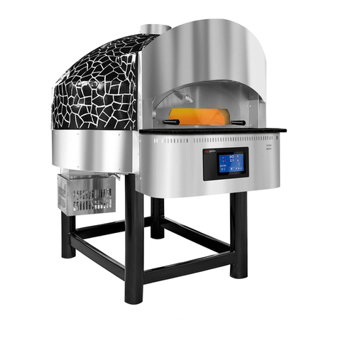
GGM gastro PDI User manual

User Manual
Pizza Ovens
PDI - PEI
GGM Gastro International GmbH
Weinerpark 16 | 48607 Ochtrup
Tel: + 49 (0) 2553 / 7220 0
Fax: +49 (0) 2553 / 7220 200
E-Mail: [email protected]
Web: www.ggmgastro.com
GGM GASTRO INTERNATIONAL GMBH ASSUMES NO
LIABILITY IN CASE OF NON-COMPLIANCE WITH GENERAL STANDARDS.
Please read the complete User Manual in order to ensure that everything runs smoothly from the outset.

CONTENTS
GENERAL IMPORTANT INFORMATION
INSTALLATION
ELECTRICAL CONNECTION
START-UP
PIZZA OVEN OPERATINING PANEL
ASSEMBLY INSTUCTIONS
PREHEATING
ALARM SIGNALS
CLEANING
MAINTENANCE
ELECTRICAL DIAGRAM
TECHNICAL CUSTOMER SERVICE
3
4
4
5
8
9
10
11
12
12
14
15
ATTENTION: PLEASE READ THE COMPLETE USER MANUAL !!!

3
GENERAL IMPORTANT INFORMATION
FOR YOUR OWN SAFETY THIS INFORMATION MUST BE OBSERVED PRIOR TO INSTALLA-
TION AND START-UP.
This device may only be operated by adults. Small children may not operate this device.
Any electronic work may be performed only by an authorised technician. Move the device with
great care.
Ensure that the supply cables are not jammed or damaged during installation.
The device may only be repaired by a qualied specialist.
Please always notify your supplier about any necessary repairs during the warranty period.
Before the device is cleaned, repaired or any other maintenance is performed, please ensure that
it is switched off and disconnected from the mains.
The device is exclusively intended for the heating of foodstuffs.
The inside temperature of the device can become close to the ambient temperature if the
pull-down doors are opened a lot of times or are not closed.
Also observe the regulations of your food suppliers.

4
INSTALLATION
Device assembly.
If necessary, install the device with the base frame at a place which contains a mains socket as
well as equipment for protecting the device operator.
Ensure there is sufcient space surrounding the device for ventilation and cleaning purposes.
The base of the oven and the feet of the base frame must be placed on a rm, even and level sur-
face. Due to the base frame, no anchoring to the oor is required.
ELECTRICAL CONNECTION
Observe the following before connecting the device: Ensure that the frequency and voltage corres-
ponds to the specications shown on the rating plate of the device.
If the device was supplied without a connection cable, it must be equipped with a suitable connec-
tion according to applicable standards.
The device must be earthed.
Should the electrical system not have an earth connection, an earth connection must be installed
in accordance with the applicable standards.

5
GGM GASTRO INTERNATIONAL GMBH ASSUMES NO
LIABILITY IN CASE OF NON-COMPLIANCE WITH GENERAL STANDARDS.
START-UP
1. Connect the device to the mains.
The connection to the mains and the start-up of the device must be performed by a specialised
skilled worker following the applicable standards in the country of the installation.
Install an outlet in the proximity of the device so that the installed mains cable can be used for
connecting. Do not use extension cables for connecting the device. Install a junction box for the
devices to be installed.
The installer must install the following devices according to the standard provisions applicable in
the country in which the device is operated:
- A suitable socket outlet and a suitable plug;
- A suitable line circuit breaker;
- A thermal circuit breaker and a differential switch appropriate for the relevant leakage
current of the resistors.
These components must be installed at the user’s expense in the proximity of the installation site
of the device.
The device must be sufciently earthed. Carry out both a visual inspection and a measurement of
the existing earthing, and if necessary, carry out the necessary modications. Connect the device
observing the prescribed techniques and take note of the cyclic sequence when connecting the
phases according to the
- L1 phase, L2 phase, L3 phase
- N/MP -neutral conductor - light blue
- PE / earth = protective conductor - YELLOW/GREEN striped
After connecting the protective devices and the supply to the oven, check the function of the
differential switch using a measuring device.

6
Make sure there are no ammable materials or other objects inside of the oven, so that the oven
can be started up to perform a preliminary test.
1. Make sure that the main switch of the device is in the O/OFF position.
2. Turn the thermostat knob and set it to a temperature of approx. 150°C.
3. Turn the main switch to the I/ON position.
4. Check the power consumption and the correct functioning of all installed lamps.
5. Wait until the thermostat stops the cycle and then set the main switch to zero.
6. From now on, the oven is ready for operation.
After completing the connection and the functional test the installer must issue a proper certicate
for the work performed.
2. Using the oven
Before using the oven, perform the following checks and take the following precautions:
1. Insert the plug into the socket of the junction box.
2. Make sure the that the main switch is in the O/Off position.
3. Make sure that the magneto-thermal circuit breaker and the differential switch are both
open.
4. Set the circuit breaker to the I/ON position.
5. Set the desired temperature with the thermostat knob.
6. Set the main switch of the oven to the I/ON position.
7. Wait until the oven has reached the desired temperature; the indicator light goes off when
the temperature has been reached.
8. When the desired temperature has been reached, open the pull-down door and place the
pizzas directly on to the reproof material, without any containers or pans underneath.

7
9. The ovens are equipped with a cooking surface made from a reproof, non-toxic special
material which is suitable for contact with foodstuffs.
10. When the pull-down door of the oven is opened hot air ows out of the oven and
consequently the temperature in the cooking cell of the pizza drops quickly. Therefore,
we recommend only opening the pull-down doors when it is absolutely necessary,
i.e. to slide in or remove the food. This reduces energy consumption and prevents
temperature uctuations in the cooking cell. The doors which are equipped with
windows allow for checking on the cooking process of the pizzas and foods without
the need to open the pull-down doors.

8
Temperature display
For increasing & reducing the temperature
Ror increasing & reducing the temperature
Interior light switch
On/off switch of the pizza ovens
Light switch: The light switch is for turning the light in the
baking chamber on and off.
Temperature knob: The temperature knob for increasing &
reducing the temperature in the baking chamber.
Power switch: This switch is used to turn on the
pizza oven.
Temperature display: Shows the temperature on
the analogue display
PIZZA OVEN OPERATINING PANEL

9
ASSEMBLY INSTUCTIONS

10
PREHEATING
Before using the oven for cooking food, the cooking cell must be suitably preheated.
> Set the thermostat of the cooking cell to a temperature of 250°C and maintain this
temperature for approx. one hour.
> When the oven is being preheated, water vapour and unpleasant odours are produced,
whereby the latter is due to the oxidation of the armoured resistors.
> Once this rst cycle has been completed, the metal is stabilised and will no longer
produce any unpleasant odours. Open the front pull-down door of the oven and keep it
open for a few minutes in order to accelerate the air exchange, then close the door again;
make sure you personally monitor the oven during this time.
> After preheating, all metal parts and the reproof material in the cooking cell have
reached the stabilisation temperature and the oven can be used as normal. When using
the oven the above described preheating cycle is no longer necessary.

11
ALARM SIGNALS
Sensor A1 and A2 alarms
The controller is equipped with alarms that are activated if the sensor is faulty. The sensor fault is
indicated by a corresponding message on the display.
A1 -Fault of the chamber temperature sensor. The G201 then prompts the turning on of the com-
pressor in the time cycle (the so-called clock control) according to the times set by the parameters
„c8“ and „c9“. Defrosting functions as normal.
A2 -Fault of the evaporator sensor. Manual and automatic defrosting is blocked! The only way to
defrost the device is to switch off the device with the button and to wait until the ice has de-
frosted naturally.
Both sensors show a fault - however only the text A1 is displayed.
Once the chamber sensor has been repaired, A2 will be displayed.
7. Alarm in case of overheating - A4 applies to program version 02.
If the temperature is higher than the parameter D6, the display will show the status „Alarm A4“
followed by the temperature; in addition, an alarm will sound (if the G-201 is equipped with audio
signals). Press any key to stop the alarm signal from sounding.

12
CLEANING
> Only operate the control elements of the oven in the specied sequence to prevent any
damage to the equipment due to improper operation.
> To clean the cooking cell, wait until the oven has cooled down completely.
> Pull the plug from the mains and put up a notice sign indicating that the oven is being
worked on.
> The plates made from the reproof material can be cleaned with a damp cloth or a wire
brush with steel bristles; do not, under any circumstances, use cleaning agents, solvents
or other chemicals. The high temperatures that are achieved in the oven ensure that the
contents of the oven are automatically sterilised. Stubborn residues, incrustations as well
as charred food residues on the reproof material can be removed using a brush or a
metal blade with a safety handle; please wear robust work gloves when performing this
work.
> The outside panels of the oven, both for the stainless steel and painted version, can be
cleaned with a damp sponge; for this you may also use a 90% biodegradable
phosphate-free and chlorine-free cleaning agent with neutral pH value.
> Do not use creamy cleaning agents which contain abrasive substances which will
damage the surfaces.
MAINTENANCE
Despite the great simplicity of use of the described ovens, some information on hazards is given
here, which cannot be avoided by the safety measures applied by the developers, and which can
arise for certain types of improper use or use of certain accessories.
> These ovens must be monitored by the operators for the entire operation cycle, even if
the ovens are equipped with a control thermostat and a safety thermostat.
> Keep the cables, outlet and plug for the oven and all safety and circuit breaker equipment
on the junction box in good condition.
> Properly protect the mains cables from any type of damage and immediately replace
them if they have become damaged, even if the damage is only supercial.
> Do not install the oven outdoors, nor under a protective roof, nor under a provisional
cover.
> The oven may only be used inside of buildings.

13
The ovens may not be used for heating or drying animals or similar.
Do not spray water, nor ammable, nor any other liquids into the inside of the oven.
Do not clean these devices with water, neither on the outside, nor inside
The ovens may be used only by staff who are trained in the operation of electrical devices;
this staff must be instructed about the dangers which can arise from improper use, or use
which is contrary to this User Manual, or from carelessness.
The user must be of the minimum age required for the intended skill to use the device, and
of the legally prescribed minimum age for performing the work.
Do not perform any cleaning or maintenance work during operation of the oven or when the
oven is cooling down: Heat and electrical energy is invisible!
Do NOT use these ovens or other devices if you do not feel well or if you are not in full pos-
session of your physical powers.
Do not use these ovens or any other devices if you are under the inuence of alcohol or
other drugs.
Before cleaning the oven, set the main switch and the circuit breaker to O/OFF, pull the
plug from the socket and put up a warning sign when performing the work: Wait until the
oven has cooled down completely; this can take several hours!
These ovens were designed and manufactured exclusively for one specic purpose, which
is essentially the cooking of pizzas and our-based foods for human consumption, i.e. at
breads, cakes, bread and pastries with or without the addition of yeast.
The oven can also be used for heating up food in containers with a raised edge, to prevent
the substance from directly touching the reproof materials, where it could ignite or create
contaminations.
These devices may only be used for the explicitly specied intended purposes.
Any charred encrustations on the walls or on the base of the oven can be removed with
non-cutting tools or wire brushes; protective gloves must be worn when doing this.
If the residues on the reproof tiles are stubborn and cannot be removed with the usual me-
ans, they must be replaced with new tiles.
The operator may not perform any repairs, nor remove any components of the oven, nor
interfere with the electrical system or any other components of the oven. Only suitably
trained maintenance staff may carry out work on the oven.
- Never climb on to the base of the oven or on the oven itself.
- Keep children away from the oven, even when it is not in use.
- Do not remove any reproof tiles from the inside of the cooking cell; immediately
replace them if they are cracked or broken.
>
>
>
>
>
>
>
>
>
>
>
>

14
ELECTRICAL DIAGRAM
Tuu Raise the resistance from the bottom shaft
Tul Lower the thermostat from the top shaft
TLu Raise the thermostat from the bottom shaft
Til Lower the thermostat from the bottom shaft
CLu Control lamp of the top shaft
CLi Control lamp of the bottom shaft
psu Switch of the top shaft control lamp
psl Switch of the bottom shaft control lamp
mcl Main cable control lamp
Ruu1 Raise the resistance from the top shaft
Rul1 Lower the resistance from the top shaft
Rlu1 Raise the resistance from the bottom shaft
Rll1 Lower the resistance from the bottom shaft
SLuu Raise the signal lamp from the top shaft
SLui Lower the signal lamp from the top shaft
Sliu Raise the signal lamp from the tbottom shaft
SLii Lower the signal lamp from the bottom shaft

GGM Gastro International GmbH
Weinerpark 16 | 48607 Ochtrup
Tel: + 49 (0) 2553 / 7220 0
Fax: +49 (0) 2553 / 7220 200
E-Mail: [email protected]
Web: www.ggmgastro.com
TECHNICAL CUSTOMER SERVICE
If you have checked all problem solutions and the device still does not function, plea-
se contact your local customer support.
GGM Technik (Service & Guarantee):
Tel.: +49 (0) 2553 / 7220 300
E-mail: [email protected]
GGM GASTRO INTERNATIONAL GMBH ASSUMES NO
LIABILITY IN CASE OF NON-COMPLIANCE WITH GENERAL STANDARDS.
15
This manual suits for next models
1
Table of contents
Other GGM gastro Kitchen Appliance manuals

GGM gastro
GGM gastro GGM24 User manual
GGM gastro
GGM gastro FMFC550 User manual
GGM gastro
GGM gastro EHK500 User manual

GGM gastro
GGM gastro GKS330N User manual
GGM gastro
GGM gastro ZWJ950 User manual
GGM gastro
GGM gastro PDKG20 Installation and operation manual
GGM gastro
GGM gastro ECTA80 User manual
GGM gastro
GGM gastro AMVH350 User manual
GGM gastro
GGM gastro DSA80S Operation instructions
GGM gastro
GGM gastro FWFC620 User manual
