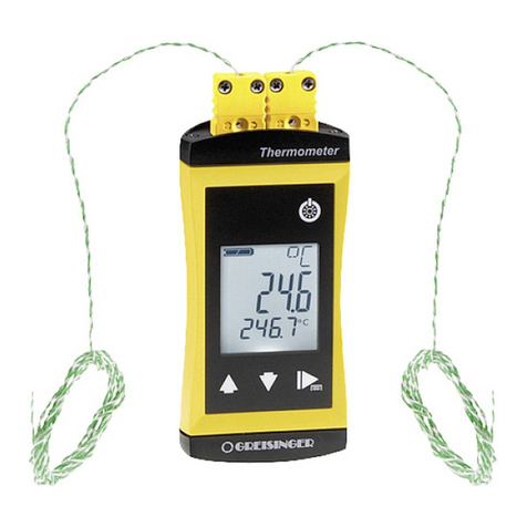
GHM GREISINGER GTH 1150 User manual

H56.0.02.6C-01
GHM GROUP - Greisinger
GHM Messtechnik GmbH | Hans-Sachs-Str. 26 | 93128 Regenstauf | GERMANY
Operating manual
Quick-Response Thermometer
As of version 1. 0
GTH 1150
Please carefully read these instructions
before use!!
WEEE-Reg.-Nr. DE 93889386
Please consider the safety instructions!
Please keep for future reference!

H56.0.02.6C-01 Operating Manual GTH 1150 Page 2 von 10
_____________________________________________________ _____________________________________________________________________________
Contents
1SAFETY......................................................................................................................................................................3
1.1 GENERAL NOTE......................................................................................................................................................3
1.2 INTENDED USE.......................................................................................................................................................3
1.3 QUALIFIED STAFF ..................................................................................................................................................3
1.4 SAFETY SIGNS AND SYMBOLS................................................................................................................................3
1.5 REASONABLY FORESEEABLE MISUSE ....................................................................................................................4
1.6 SAFETY GUIDELINES..............................................................................................................................................4
2PRODUCT DESCRIPTION......................................................................................................................................4
2.1 SCOPE OF DELIVERY ..............................................................................................................................................4
2.2 OPERATING AND MAINTENANCE...........................................................................................................................5
3OPERATION..............................................................................................................................................................5
3.1 DISPLAY ELEMENT ................................................................................................................................................5
3.2 PUSHBUTTONS.......................................................................................................................................................5
3.3 CONNECTIONS .......................................................................................................................................................5
4ADJUSTMENT...........................................................................................................................................................6
4.1 MANUAL ADJUSTMENT .........................................................................................................................................6
4.1.1 Zero point-Adjustment....................................................................................................................................6
4.1.2 Scale Adjustment............................................................................................................................................6
5BASICS OF THE MEASUREMENT.......................................................................................................................6
5.1 PROBE ACCURACY/DEVICE ACCURACY.................................................................................................................6
5.2 POSSIBLE ERRORS..................................................................................................................................................6
5.2.1 Immersion depth.............................................................................................................................................6
5.2.2 Surface effects and bad heat transfer.............................................................................................................6
5.2.3 Cooling (evaporation)....................................................................................................................................6
5.2.4 Response time.................................................................................................................................................6
5.2.5 Limit values....................................................................................................................................................7
6TYPE K-SENSOR......................................................................................................................................................7
6.1 DETAILS ABOUT THE SENSORS ..............................................................................................................................7
6.2 SENSORS................................................................................................................................................................7
6.2.1 GF 1TK-T3.....................................................................................................................................................7
6.2.2 GF 1TK-E1.5..................................................................................................................................................7
6.2.3 GF 1TK-E3.....................................................................................................................................................7
6.2.4 GES 130 .........................................................................................................................................................7
6.2.5 GOF 130 ........................................................................................................................................................7
6.2.6 GFT 300.........................................................................................................................................................8
7REPLACING BATTERIES......................................................................................................................................8
8FAULT AND SYSTEM MESSAGES.......................................................................................................................9
9RESHIPMENT AND DISPOSAL.............................................................................................................................9
9.1 RESHIPMENT..........................................................................................................................................................9
9.2 DISPOSAL...............................................................................................................................................................9
9SPECIFICATION ....................................................................................................................................................10
H56.0.02.6C-01 Operating Manual GTH 1150 Page 3 von 10
_____________________________________________________ _____________________________________________________________________________
1 Safety
1.1 General note
Read through this document attentively and make yourself familiar to the operation of the device before you
use it. Keep this document in a ready-to-hand way in order to be able to look up in the case of doubt.
Mounting, start-up, operating, maintenance and removing from operation must be done by qualified,
specially trained staff that have carefully read and understood this manual before starting any work.
The manufacturer will assume no liability or warranty in case of usage for other purpose than the intended
one, ignoring this manual, operating by unqualified staff as well as unauthorized modifications to the device.
The manufacturer is not liable for misprints.
1.2 Intended Use
The device is designed for temperature measurements in various media in seconds.
The measuring range is -50... +1150 °C.
The device has a 2-pole standard flat-plug connection suitable for all type K thermocouple probes. Refer to
chapter 6 Type K-sensor to view a selection of the available probes.
The safety requirements (see below) have to be observed.
The device must be used only according to its intended purpose and under suitable conditions.
Use the device carefully and according to its technical data (do not throw it, strike it …)
Protect the device from dirt.
1.3 Qualified staff
All instructions have to be well understood and complied with.
To be sure that there´s no risk arising due to misinterpretation of measured values, the operator must have
further knowledge in case of doubt - the user is liable for any harm/damage resulting from misinterpretation
due to insufficient knowledge.
1.4 Safety signs and symbols
Warnings are labeled in this document with the followings signs:
Caution! This symbol warns of imminent danger, death, serious injuries and significant
damage to property at non-observance.
Attention! This symbol warns of possible dangers or dangerous situations which can
provoke damage to the device or environment at non-observance.
Note! This symbol point out processes which can indirectly influence operation, possibly
cause incorrect measurement or provoke unforeseen reactions at non-observance.

H56.0.02.6C-01 Operating Manual GTH 1150 Page 4 von 10
_____________________________________________________ _____________________________________________________________________________
1.5 Reasonably foreseeable misuse
This device must not be used at potentially explosive areas!
Do not use these products as safety or emergency stop devices or in any other application
where failure of the product could result in personal injury or material damage.
Failure to comply with these instructions could result in death or serious injury and
material damage.
This device must not be used at a patient for diagnostic or other medical purpose.
1.6 Safety guidelines
This device has been designed and tested in accordance with the safety regulations for electronic devices.
However, its trouble-free operation and reliability cannot be guaranteed unless the standard safety measures
and special safety advises given in this manual will be adhered to when using the device.
If there is a risk whatsoever involved in running it, the device has to be switched off
immediately and to be marked accordingly to avoid re-starting.
Operator safety may be a risk if:
- there is visible damage to the device
- the device is not working as specified
- the device has been stored under unsuitable conditions for a longer time.
In case of doubt, please return device to manufacturer for repair or maintenance.
Due to the pointed probe design there is a risk of stitch injury for devices with insertion
probe.
Trouble-free operation and reliability of the device can only be guaranteed if the device is
not subjected to any other climatic conditions than those stated under 0
Specification.If the device is transported from, a cold to a warm environment condensation
may cause in a failure of the function. In such a case, make sure the device temperature
has adjusted to the ambient temperature before trying a new start-up.
2 Product description
2.1 Scope of delivery
The scope of supply includes:
GTH 1150
GTH 1150- Gourmet- SET
Device
Device
9V- battery
9V- battery
Operating Manual
Operating Manual
Sensor GTE 130 OK

H56.0.02.6C-01 Operating Manual GTH 1150 Page 5 von 10
_____________________________________________________ _____________________________________________________________________________
2.2 Operating and Maintenance
Battery operation:
If the "BAT" symbol is displayed at the bottom left of the display, the battery is weak and should be replaced
soon. However, the device will still operate for a certain length of time.
If an additional "BAT" symbol is shown in the display, the battery is depleted. Battery replacement: (see
chapter 7 Fehler! Verweisquelle konnte nicht gefunden werden.).
The battery has to be removed, when storing device above 50°C.
We recommend taking out the batteries if device is not used for a longer period of time.
Treat device and probes carefully. Use only in accordance with above specification. (do
not throw, hit against etc.). Protect plug and socket from soiling.
Make sure that the device and the probe plug are always exposed to the same
temperature. Therefore, do not hold the probe plug in your hand too long and do not
expose the device to an additional heat source; otherwise faulty measurements can occur.
Wire probes, e.g.: GTF 300 can be shortened or, in case of a break, repaired by stripping
about 10mm of the insulation off of the wire ends and twisting them together.
Measurement is not possible with open wire ends.
3 Operation
3.1 Display element
Current temperature Measured value
BAT: Low battery
3.2 Pushbuttons
Slide on / off
Position 0 = off
Position 1 = on
3.3 Connections
Scale (pitch potentiometer)
NP (NP potentiometer)
2-pole Norm-flat connection suitable for all NiCr-Ni
(Typ K)- sensors

H56.0.02.6C-01 Operating Manual GTH 1150 Page 6 von 10
_____________________________________________________ _____________________________________________________________________________
4 Adjustment
The device is calibrated and adjusted at the factory so that any standard probe offered by Greisinger can be
plugged in without recalibration. If the value deviates excessively over time, we offer factory re-calibration.
4.1 Manual Adjustment
Manual adjustment changes the factory settings, which can no longer be simply restored!
If you want to adjust the device to the available probe, the probe must be plugged in first. Then the zero-
point potential must be adjusted. See chapter Fehler! Verweisquelle konnte nicht gefunden werden.
Connections.
Ensure that the thermometer has adjusted to room temperature for the zero-point
potentiometer adjustment!
4.1.1 Zero point-Adjustment
Put ice cubes in a glass and pour cold water until ice cubes are almost covered. Put sensor into glass, wait
approx. 30 minutes, then stir water with a spoon handle. Wait for stable value to be displayed, and then turn
zero point potentiometer by means of a screwdriver until display shows 0.
4.1.2 Scale Adjustment
An additional temperature reference is required for the scale adjustment. Adjust the display with the gradient
potentiometer (scale) to the desired reference value.
5 Basics of the measurement
5.1 Probe accuracy/device accuracy
DIN EN 60584-2
Class
Type
Deviation
Validity
1
K
+/- 1.5 °C
-40… +375 °C
5.2 Possible errors
5.2.1 Immersion depth
For measurements in liquids the probe should be immersed sufficiently deep (depending on probe
diameter, at least 20 mm with Ø 3 mm and 10 mm with Ø 1.5 mm) and subsequently stirred.
When measuring gases the probe should also emerge as deep as possible in the gas to be
measured (e.g. when measuring in channels/pipes) and the gas should flow around the probe at
sufficient flow.
5.2.2 Surface effects and bad heat transfer
For surface temperature measurements special surface probes are necessary. Surface quality, heat
transfer and ambient temperature have an influence on the measurement result.
Thermally conductive paste between the probe and surface can also increase
measurement accuracy in some cases.
5.2.3 Cooling (evaporation)
For air temperature measurements, the probe should be dry, otherwise it can be possible that a too
low temperature could be measured.
5.2.4 Response time
Before reading the measured value at the measuring process, it is necessary to wait a sufficient time
(see chapter 6 Type K-sensor).

H56.0.02.6C-01 Operating Manual GTH 1150 Page 7 von 10
_____________________________________________________ _____________________________________________________________________________
5.2.5 Limit values
If this is disregarded, the probe can be destroyed!
Thermocouples are suitable for detecting very large temperature ranges. However, the permissible limits of
your probe must be observed when measuring high temperatures. See chapter 6 Type K-sensor.
6 Type K-sensor
6.1 Details about the sensors
Application
Temperature range
Response time T90
Sensor
Insertion sensor
-65… +550 °C
40 s
GF 1TK- T3
Einstechfühler für weichplastische
Medien
-65… +550 °C
12 s
GF 1TK- E1.5
-65… +550 °C
40 s
GF 1TK- E3
-65… +550 °C
3 s
GES 130
Surface senosr
-65… +900 °C
2 s
GOF 130
Wire sensor
-65… +300 °C
0,3 s
GTF 300
6.2 Sensors
6.2.1 GF 1TK-T3
6.2.2 GF 1TK-E1.5
6.2.3 GF 1TK-E3
6.2.4 GES 130
6.2.5 GOF 130

H56.0.02.6C-01 Operating Manual GTH 1150 Page 8 von 10
_____________________________________________________ _____________________________________________________________________________
6.2.6 GFT 300
You will find more Type K sensors in our catalogue on page 24 to 27.
7 Replacing batteries
The use of damaged or unsuitable batteries could lead to further heating, whereby the
batteries can burst or in the worst case exploding.
Ensure that the device is switched off when replacing the battery. The switch must be in Position 0, see
chapter Fehler! Verweisquelle konnte nicht gefunden werden. Fehler! Verweisquelle konnte nicht ge
funden werden. and turn it over so that the rear side is facing upwards.
1.) Open the cover of the device by carefully pushing it off of the device.
2.) Pull the battery out of the compartment and disconnect it.
3.) Ensure correct polarity when replacing the battery!
4.) Insert the battery in the compartment. Then position the cover correctly and slide it in until it engages.

H56.0.02.6C-01 Operating Manual GTH 1150 Page 9 von 10
_____________________________________________________ _____________________________________________________________________________
8 Fault and System Messages
Error messages for measurement
Description
What to do?
ER.1
Measured value above allowable range
Check: temperature not within sensor range?
-> measuring value to high!
ER.2
Measured value below allowable range
Check: temperature not within sensor range?
-> measuring value to low!
ER.7
System error
Note the working temperature of the device.
Switch off the device and switch on again -
when the error remains
return to manufacturer for repair
BAT
Low battery
See chapter 7 Replacing batteries
BATBAT
battery is ultimately exhausted
See chapter 7 Replacing batteries
----
• no suitable probe connected
Check: is a suitable probe connected?
9 Reshipment and disposal
9.1 Reshipment
All devices returned to the manufacturer have to be free of any residual of measuring media
and other hazardous substances.
Measuring residuals at housing or sensor may be a risk for persons or environment
Use an adequate transport package for reshipment, especially for fully functional devices.
Please make sure that the device is protected in the package by enough packing materials.
Add the completed reshipment form of the GHM website
http://www.ghm-messtechnik.de/downloads/ghm-formulare.html.
9.2 Disposal
Dispense exhausted batteries at destined gathering places The device must not be disposed in
the unsorted municipal waste! Send the device directly to us (sufficiently stamped), considering
the above if it should be disposed. We will dispose the device appropriate and environmentally
sound.
Private user can return the device at the municipal collection points for small electrical
appliances.

H56.0.02.6C-01 Operating Manual GTH 1150 Page 10 von 10
_____________________________________________________ _____________________________________________________________________________
9 Specification
Resolution
1 °C
Measuring range
-50 … 1150 °C
Accuracy(at nominal temperature)
±0.2 % v.MW. ±0.2 % FS.
For more detailed values please refer to chapter 5 Basics of
the measurement
Sensor
Type K (NiCr-Ni), acc. to ½ DIN 43710, for plug-in operation.
(Not included in scope off supply). Special design sensors
incl. one of the following probes see chapter 6 Type K-sensor
Nominal temperature
25 °C
Working temperature
0 to +45 °C, please avoid quick temperature changes, if
possible, otherwise a temperature adjustment time of approx.
15 minutes has to be taken into account
Atmospheric humidity
0 … 80 % RH (not-condensing)
Storage temperature
-25 … +70 °C (Over 50 °C please remove battery)
Display
approx. 13 mm high, 3½-digit LCD
Power supply
9V-Battery, type IEC 6F22
Battery service life
> 1000 hours
Low battery warning
„BAT“displayed automatically in case of low battery.
Dimensions of case
106 x 67 x 30 mm (L x B x D)
Weight
approx. 130 g (including battery)
Directives and standards
The instruments confirm to following European directives:
2014/30/EU EMV directives
2011/65/EU RoHS
2012/19/EU WEEE
Applied harmonized standards:
EN 61326-1:2013 emissions level: class B
emi immunity according to table
1 /A.1
additional error: < 0.5 % FS
EN 50581:2012
The device is for the mobile application or for the stationary
operation in the course of specified working conditions
without further restrictions construed.
Table of contents
Other GHM Thermometer manuals

GHM
GHM Delta OHM HD2307.0 User manual

GHM
GHM GREISINGER Gourmet Thermometer User manual

GHM
GHM Delta OHM HD2108.1 User manual

GHM
GHM GREISINGER G 1730 User manual

GHM
GHM Greisinger GTH 2448/2 User manual

GHM
GHM GREISINGER G 1700 Series Installation instructions

GHM
GHM Greisinger G 1200 Installation instructions

GHM
GHM GREISINGER G 1202 Installation instructions

GHM
GHM GREISINGER GTH 2448 / 1 User manual

GHM
GHM Delta OHM HD2328.0 User manual