GHM Delta OHM HD2328.0 User manual

HD2328 - 2 - V1.7
CON TEN TS
GEN ERAL CH ARACTERI STI CS............................................................................................................................ 3
DESCRI PTI ON OF TH E FU N CTI ON S ............................................................................................................... 6
TH E PROGRAM M I N G MEN U ................................................................................................................................ 9
PROBES AN D M EASU REM EN TS ....................................................................................................................... 10
TEMPERATURE MEASUREMENT ................................................................................................................................... 10
CALI BRATI ON OF THE I NSTRUMENT ON LI NE WI TH THE PROBE(S)......................................................................... 10
CALI BRATI ON SEQUENCE –INSTRUMENT ON LI NE WI TH THE PROBE(S) : .............................................................. 11
W ARN I N GS ................................................................................................................................................................ 12
I N STRU M EN T SI GN ALS AN D FAULTS ......................................................................................................... 13
I NSTRUM ENT STORAGE...................................................................................................................................... 13
LOW BATTERY W ARN I N G AN D BATTERY REPLACEM EN T ............................................................... 14
WARNI NG ABOUT BATTERY USE ................................................................................................................................. 14
N OTES ABO UT W ORKI N G AN D OPERATI VE SAFETY .......................................................................... 15
I N STRUM EN T TECH N I CAL CH ARACTERI ST I CS ..................................................................................... 16
ORD ERI N G COD ES ................................................................................................................................................. 18

HD2328 - 3 - V1.7
GEN ERAL CHARACTERI STI CS
The Therm ocouple Ther m om et er Model H D 2 3 2 8 .0 is a port able inst rum ent w it h t wo
input s A and B. I t m easures t he tem perat ure of the t wo input channels, and can
calculat e t he difference bet w een t he t wo channels ( A-B) .
I t is fit t ed wit h a lar ge LCD display for ex cellent v isualizat ion of t he m easur ed dat a.
The Therm om et er Model HD 2 3 2 8 .0 m easures t he t em per at ure using im m ersion,
penet ration, cont act or air probes.
The sensor can be a t herm ocouple chosen am ong the following t ypes:
•Type K
•Type J
•Type T
•Type E
The inst rum ent accept s the input of one, or t wo, therm ocouples of t he sam e type ( K-
J- T- E) even in a different form .
The unit s of m easurem ent are the follow ing:
1. ° C ( Celsius degr ees)
2. ° F ( Fahrenheit degr ees) .
Using t he Max, Min and Av g funct ion of t his inst r um ent respect iv ely obt ains also t he
m axim um , m inim um or average values.
Ot her av ailable funct ions are:
•t he relat iv e m easur em ent REL;
•the HOLD funct ion;
•the A-B funct ion;
•the aut om at ic turning off which can also be disabled.
The inst rum ent is pr ovided w it h t he fact ory calibr at ion. I t is also possible t o perfor m a
"User Calibrat ion" of inst rum ent + probe ( see dedicat ed chapt ers) .

HD2328 - 4 - V1.7
Therm ocouple Therm om et er
H D 2 3 2 8 .0

HD2328 - 5 - V1.7
HD 2 3 2 8 .0
1. I nput s A and B for t w o t her m ocouples, w it h st andar d m iniat ure connect ors.
2. Batt ery sym bol: displays t he bat t ery charge level.
3. Funct ion indicat ors.
4. Secondary display line.
5. D ATA/ EN TER key: during norm al operation displays t he m ax im um ( MAX) , t he
m inim um ( MI N) and t he av erage ( AVG) of cur rent m easurem ent s; in t he m enu,
confirm s t he cur rent select ion.
6. CLR/ ESC key: during norm al oper at ion reset s the m axim um , t he m inim um and
t he average of current m easurem ent s; in t he m enu, it reset s the value set wit h the
arrows.
7. H OLD/ key: fr eezes t he m easur em ent display dur ing nor m al operat ion; in t he
m enu, increases t he current value.
8. A- B/ M EN U key: during nor m al operat ion, it displays in t he secondary line t he
difference of t he t em perat ures m easured by t he probes connect ed t o t he input s A
and B; when pressed t ogether wit h t he DATA key, it allows t o open t he m enu.
9. REL/ key: dur ing norm al operat ion enables t he r elat iv e m easur em ent ( displays
the difference between t he current value and t he logged value when t he key is
pressed) ; in t he m enu, decreases the current value.
10.ON -OFF/ AUTO-OFF key: t urns t he inst rum ent on and off; w hen pressed t ogether
wit h t he HOLD key, disables t he Aut oPowerOff funct ion.
11.M AX ( m ax im um v alue) , M I N ( m in im um value) and AVG ( aver age v alue) sym bols.
12.Main display line.
13.Line for sym bols and com m ents.

HD2328 - 6 - V1.7
DESCRI PTI ON OF TH E FUN CTI ON S
The keyboard of t he Therm ocouple Therm om et er Model H D 2 3 2 8 .0 is com posed of
double-funct ion keys. The funct ion on t he key is t he "m ain funct ion", while t he one
above t he key is the " secondary funct ion".
When t he inst rum ent is in st andard m easurem ent m ode, t he m ain funct ion is act ive.
I n the m enu, the secondary funct ion is enabled; press the DATA+ ( A-B) keys
t oget her t o open t he m enu.
The pressing of a key is accom panied by a short confirm at ion " beep" : a longer " beep"
sounds if the wrong key is pressed. Each key specific funct ion is descr ibed in det ail
below.
The H D2 3 2 8 .0m easur es t he t em perat ure at t he tw o input s: t he t em perat ure
m easurem ent at t he " A" input is displayed in t he m ain line, while t he secondary line
shows t he v alue at t he " B" input .
This key has t wo funct ions:
•ON / OFF: t o t urn t he inst rum ent on press ON , t o turn it off press OFF.
The t urning on enables all display segm ent s for a few seconds, and t hen t he t ype of
calibr at ion enabled ( CAL FACT = fact ory calibrat ion; CAL USER = user calibrat ion) .
•AUTO/ OFF: t he Au t o Po w e r O f f funct ion can be disabled by sim ult aneously
pressing t his key and t he "HOLD" key when t urning t he inst rum ent on.
I f no probe is connect ed to one of the in put connectors, t h e " BURN " m e ssa ge
appears in the cor responding line, t hat is, in the first line for input "A" and in
the second lin e for input " B".
The inst rum ent has an Aut oPowerOff funct ion t hat aut om at ically t urns t he instrum ent
off aft er about 8 m inut es if no key is pr essed dur ing t he int er vening t im e.
Press sim ult aneously t he ON / OFF key and t he HOLD key t o disable t h is funct ion.
I n t his case, rem em ber t o t urn t he inst rum ent off using t he ON / OFF key: disabling of
t he aut om at ic t urning off is shown by t he blink ing bat tery sym bol.
ON -OFF a nd AUTO-OFF
Disa blin g of the a ut om at ic t urning off

HD2328 - 7 - V1.7
The DATA key is used for the following funct ions:
•DATA: during norm al m easurem ent , by pressing t his key once the m axim um
( MAX) value of t he m easurem ent s capt ured by t he probes connect ed t o t he
inst rum ent is display ed, updat ing it w it h t he acquisit ion of new sam ples;
- by pressing t his key again the m inim um ( MI N) value is display ed;
- by pr essing t his key a t hird t im e t he average ( AVG) v alu e is display ed .
The acquisition frequency is once a second.
The MAX, MI N and AVG values rem ain in t he m em ory unt il t he inst rum ent is on,
ev en aft er exit ing t he DATA display funct ion. When t he inst r um ent is off, t he
previously m em orized dat a are cleared. Upon t ur ning on, t he instrum ent
autom at ically st art s m em orizing t he MAX, MI N and AVG values.
To reset t he previous values and st art with a new m easurem ent session, press
CLR unt il t he FUNC_ CLRD m essage appears.
•EN TER: once t he MENU has been opened wit h the D ATA+ UN I T keys, t he D ATA
key will perform the ENTER funct ion and t he MENU can be browsed and the
displayed param et er confirm ed.
The CLR key has t wo funct ions:
•CLEAR ( CLR) : allow s t o reset t he m axim um ( MAX) , m inim um ( MI N) and average
( AVG) value of t he capt ur ed m easur em ent s;
•ESC: once the MENU has been opened wit h t he DATA+ UN I T keys, t he CLR k ey
will allow t o cancel the param et ers set using t he and arrows.
The H OLD key is used for the following funct ions:
•HOLD: by pressing t his key t he current m easurem ent updat e is st opped and t he
"HOLD" m essage will appear in t he upper left -hand corner of t he display. To ret urn
t o t he current m easurem ent , press t he key again.
•: once the MENU has been opened wit h t he D ATA+ UN I T keys, t he key will
allow t o increase t he value of t he select ed param et er.
Pressed t ogether wit h t he ON / OFF key, during turn on, t he AutoPowerOff funct ion is
disabled ( see t he descr ipt ion of t he ON/ OFF key) .
D ATA/ EN TER k e y
HOLD/ k e y
CLR/ ESC key

HD2328 - 8 - V1.7
The A- B k ey is used for t he follow ing funct ions:
•A- B: in m easurem ent m ode, it displays in t he secondary line t he difference of t he
t em perat ures m easured by t he probes connected t o t he input s Aand B, and
indicat es " ERR" if one of t he probes is in error ( not connect ed, fault y or
over range) . To end t he funct ion, pr ess t he key again.
•M EN U : in the m enu t hree it em s can be set:
1. Select ion of t he unit of m easurem ent for t em perat ure: ° C or ° F.
2. Selection of t he type of Therm ocouple: K, J, T, E.
3. St ar ting t he User calibr at ion pr ocedure.
- t he m enu is opened by pressing sim ult aneously DATA+ ( A-B) : t he first it em of t he
inst rum ent program m ing m enu will appear;
- use the and arrows ( r espect iv ely locat ed above t he HOLD and REL k eys) t o
m odify t he display ed v alue;
- press DATA/ EN TER t o con firm t he m odificat ion and go ont o t he next it em ;
- press CLR/ ESC to ca nce l t h e m odif icat ion;
- to e x it t he m enu, press t he A- B/ M EN U key again.
The REL key is used for t he follow ing funct ions:
•REL: it displays t he difference between t he current value and that m easured on
pressing t he key for bot h m easurem ent s: m ain and secondary. The "REL" m essage
is displayed on the left . To ret urn t o t he norm al m easurem ent , press t he key
again.
•: once t he MENU has been opened wit h t he D ATA+ ( A-B) keys, t he key w ill
allow t o decrease t he value of t he select ed param et er.
REL/ k e y
A- B/ M EN U k e y

HD2328 - 9 - V1.7
TH E PROGRAM M I N G M EN U
To access to the programming menu press simultaneously the DATA+(A-B) keys.
The items to be set are listed in this order:
1 . Se le ct ion of the unit of m easurem ent: t he " SEL_ MEAS_ UN I T" m essage is
displayed in t he com m ent line. The m ain line in t he cent er of t he display shows
the select ed unit of m easurem ent : Celsius (° C) or Fahrenheit ( ° F) degrees.:
•use the and arr ow s ( respect iv ely locat ed abov e t he HOLD and
REL keys) to m odify t he t ype of probe;
•press DATA/ EN TER t o con firm t he m odificat ion and go ont o t he next
it em ;
•press CLR/ESC to ca n cel t he m odificat ion ;
•to e x it t he m enu, press t he A- B/M EN U key again.
2 . Se le ct ion of t h e t ype of Th e rm ocouple : the " SEL" m essage is displayed in
the m ain line, while t he t ype of probe is displayed in t he com m ent line; in t he
secondary line is shown t he " t c" m essage.
The t ypes of t her m ocou ple t h a t ca n be se lect ed a re: K, J, T, or E.
•use the and arr ow s ( respect iv ely locat ed abov e t he HOLD and
REL keys) to m odify t he t ype of therm ocouple;
•press DATA/ EN TER t o con firm t he m odificat ion and go ont o t he next
it em ;
•press CLR/ESC to ca n cel t he m odificat ion ;
•to e x it t he m enu, press t he A- B/M EN U key again.
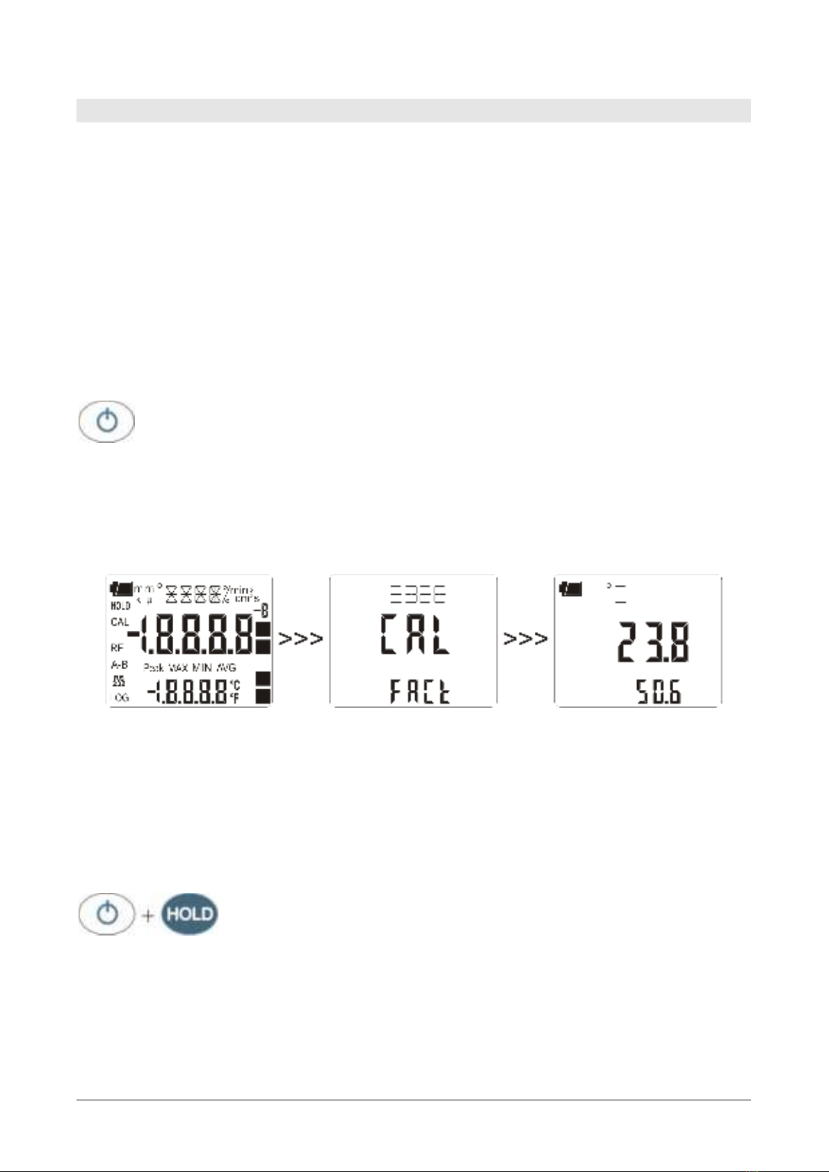
3 . St a rt in g t h e U se r ca libr a t ion pr oce du r e: the " > > > _ CAL_ MODE" m essage
is displayed in t he com m ent line, and " FACt " is displayed in t he m ain line.
The inst rum ent is pr ovided wit h t he fact or y ( "FACt ") calibr at ion. I t is also
possible t o perfor m a " USER calibrat ion" ("USEr " )of inst rum ent + probe. The
calibr at ion infor m at ion is saved in t he inst rum ent ’s m em ory. The sam e
correct ion is applied t o any pr obe connect ed t o t he input : therefore, t he "USER
calibr at ion" should only be used w it h t he pr obe used for calibrat ion and not w it h
ot her probes.
•use the and arrow s ( r espect ively locat ed abov e t he HOLD and REL
keys) and select USEr, t o acce ss t he " USER calibr at ion" procedur e;
•press D AT A/ EN TER t o con fir m t he m odificat ion;
•the " SEL_ CH AN " m essage is displayed in t he com m ent line;
•use the and arrow s ( r espect ively locat ed abov e t he HOLD and REL
keys) t o select t he input "A" or " B" in t he m ain line;
•the " SEL_ MEAS_ 1 / 2 " m essage is display ed in t he com m ent line;
•use the and arrow s ( r espect ively locat ed abov e t he HOLD and REL
keys) t o select " 0 " , "1 " or "2 " in t he m ain line;
•press D AT A/ EN TER t o con fir m t he m odification;
•pr ess CLR/ ESC t o cancel t he m odificat ion;
•to e x it t he m enu, press t he UNI T/M EN U key again.

HD2328 - 10 - V1.7
PROBES AN D M EASUREM EN TS
The inst rum ent works wit h t herm ocouple probes of type K, J, T, or E.
See chapt er ‘The program m ing m enu’for t he selection of t he t ype of probe.
The cont act s of the t herm ocouple probe connect or are polarized. They m ust be
insert ed on t he st andard m iniature socket locat ed on t he inst rum ent in t he correct
direct ion. These probes are usually m ar ked w it h a "+ " and " –" sign.
The user can choose t he unit of m easurem ent for display of t em perat ure: ° C and ° F.
The Therm om et er HD2 3 2 8 .0 has t wo input s: t he t em per at ure for input " A" ( see
descr ipt ion of t he input s) is displayed in t he m ain line: t he t em per at ure for input " B"
is d isp layed in t h e secondar y line. When t he " A-B" function is enabled, the relevant
different ial t em perat ure is displayed in t he secondary line.
I f tw o pr obes ar e used, th ey m ust be t h e sa m e t ype of ther m ocou ple .
TEM PERATURE MEASUREM EN T
I n all versions t he t herm ocouple hot j unct ion is housed in t he end part of the probe.
The response t im e for the m easurem ent of the t em perat ure in a ir is great ly r educed if
t he air is m ov ing. I f t he air is st ill, st ir t he pr obe. The r esponse t im es ar e longer t han
t hose for liquid m easurem ent s.
The t em perat ure m easured by im m e r sion is carr ied out by insert ing t he probe in t he
liquid, in t he oven where you wish t o perform t he m easurem ent ; t he hot j unct ion is
housed in t he end part of t he probe.
I n t he t em per at ure m easured by pe ne t r at ion t he probe t ip m ust be inser ted int o t he
m at erial; t he hot j unct ion is housed in t he end part of t he pr obe.
N OTE: when m easuring t he t em perat ure on frozen blocks it is convenient to use a
m echanical tool t o bore a cavit y in which t o insert the t ip probe.
I n order t o perform a correct con t a ct m easur em ent , t he m easur em ent sur face m ust
be even and sm oot h, and t he probe m ust be perpendicular to the m easurem ent plane.
So a s t o obt a in t h e cor r ect m e asur em e n t , t h e in se rt ion of a dr op of oil or
h ea t -condu ct ive past e bet w e e n the su r fa ce and th e pr obe is usefu l ( do not
use w at er or solve nt s) . Th is m ethod also im pr oves t he response t im e.
CALI BRATI ON OF THE I N STRU MEN T ON LI N E W I TH TH E PROBE(S)
To calibrate t he probes correct ly, a knowledge of and abiding by t he physical
phenom ena on w hich t he m easurem ent is based is fundam ent al: this is t he reason
why it is recom m ended t o abide by what is report ed below carefully, and only t o
perform new calibr at ions if t echnically proficient and using t he suit able equipm ent .
The inst rum ent is provided wit h the only FACT ( fact ory ) calibr at ion.
The user is also able t o perform a USER ca libr a t ion of inst rum ent + probe.

HD2328 - 11 - V1.7
The calibrat ion inform at ion is saved in the inst rum ent 's m em ory. The sam e correct ion
is applied to any probe that is subsequent ly connect ed to the input : therefore, the
"USER calibrat ion" should only be used wit h t he probe used for calibrat ion and not
wit h ot her probes.
To pass from t he user t o t he fact ory calibrat ion and back, proceed as follows:
•press sim ult aneously ( A- B) / M EN U and D ATA/ EN TER t o open t he m enu:
•press EN TER unt il t he m enu it em "CAL_ M ODE" is selected.
•use the and arrows ( r espect iv ely locat ed above t he HOLD and REL k eys) t o
select t he t ype of calibr at ion, FACT or USER;
•confirm by pressing D ATA/ EN TER.
CALI BRATI ON SEQUEN CE –IN STRU MEN T ON LI N E W I TH TH E PROBE(S) :
The calibrat ion can be carried out on one or t wo point s t h at sh ou ld d if fe r by a t
le a st 1 0 ° C and be included in t he probe functioning range.
1. I nsert t he probe int o a t her m ost at ic bat h, t he t em perature of which is precisely
known from a reading t aken on a sam ple reference t herm om et er. Wait for t he
m easurem ent t o st abilize.
2. Press sim ultaneously ( A- B) / M EN U and D ATA/ EN TER t o open t he m enu.
3. Press D ATA/ EN TER until t he m enu it em " CAL_ M OD E" is select ed.
4. Use the and ar row s ( r espect ively locat ed abov e t he HOLD and REL k eys) t o
select t he USER calibrat ion.
5. Confirm wit h D ATA/ EN TER.
6. Use the and ar row s ( r espect ively locat ed abov e t he HOLD and REL k eys) t o
select t he input to w hich t he probe being calibrated is connect ed, choosing t he
upper connect or A or the lower one B.
7. Confirm wit h D ATA/ EN TER.
8. The " SEL_ M EAS_ 1 / 2 " m essage is displayed in t he com m ent line.
9. Use the and arrows t o select " 1 " ( fir st calibr at ion point ) .
10.Confirm with D ATA/ EN TER.
11.The " UP D OW N 1 st M EAS" m essage is displayed in t he com m ent line: t he
inst rum ent display shows the m easured t em perat ur e.
12.Use the and arr ow s t o cor rect t he indicat ed value unt il it coincides wit h t he
value m easured by t he sam ple reference therm om et er.
13.Confirm with D ATA/ EN TER.
14.To exit t he procedure wit hout perform ing t he second point , select " 0 " and press
EN TER.
15.To calibr at e t he second point , select t he point "2 " using t he and arrows.
16.Press D ATA/ EN TER.
17.The " UP D OW N 2 n d M EAS" m essage is displayed in t he com m ent line.
18.Move t he probe t o t he second t herm ost at ic bath and wait for t he m easurem ent t o
stabilize.
19.The inst rum ent display shows t he m easur ed t em perat ur e.
20.Use the and arr ow s t o cor rect t he indicat ed v alue unt il it coincides wit h t he
value m easured by t he sam ple refer ence t herm om et er.
21.Confirm with D ATA/ EN TER.
The procedure is now com plet e.

HD2328 - 12 - V1.7
WARN I N GS
1. Do not expose the probes to gases or liquids t hat could corrode t he m aterial of t he
probe. Clean t he probe carefully aft er each m easurem ent .
2. Do not bend the probe connectors or force t hem upward or downward.
3. Com ply w it h t he correct polarit y of t he pr obes.
4. Do not bend or force t he cont act s when inser t ing t he probe connect or int o t he
inst rum ent .
5. Do not bend, deform or drop the probes, as this could cause irreparable dam age.
6. Always select t he m ost suitable probe for your applicat ion.
7. I n general, do not use tem perat ure probes in presence of corrosive gases or
liquids; the probe external cont ainers are m ade of AI SI 316 or I NCONEL st ainless
steel, while the cont act probe cont ainers are m ade from AI SI 316 or I NCONEL
stainless steel plus silver. Avoid contact between the probe surface and any sticky
surface or product t hat could corrode or dam age it .
8. To obt ain reliable m easurem ent s, t em perat ure variat ions t hat are t oo rapid m ust
be avoided.
9. Tem perat ure probes for surface m easurem ent s ( cont act probes) m ust be held
perpendicular against t he surface. Apply oil or heat-conduct ive past e bet ween t he
surface and t he probe in or der t o im pr ove cont act and reduce r eading t im e.
What ever you do, do not use wat er or solvent for t his purpose. A contact
m easurem ent is always very hard t o perform . I t has high levels of uncert aint y and
depends on the abilit y of the operator.
10.Tem per at ure m easurem ent s on non-m et al sur faces usually require a great deal of
t im e due t o t he low heat conduct iv it y of non-m et al m at er ials.
11.The sensor is not insulat ed from it s ext er nal casing; be very careful not t o com e
int o cont act w it h live part s ( above 48V) . This cou ld be ext rem ely
dangerous for t he inst rum ent as well as for t he operat or, who could be
elect rocut ed.
12.Avoid tak ing m easurem ent s in presence of high frequency sources, m icrowave
ovens or large m agnet ic fields; result s m ay not be very reliable.
13.The inst rum ent is wat er resist ant , but should not be im m ersed in wat er. Should
t he inst rum ent fall int o t he wat er, check for any w at er in filt rat ion from t he
connect ors' side. Gently handle t he inst rum ent in such a way as to prevent any
wat er infilt rat ion fr om t he connect ors' side.

HD2328 - 13 - V1.7
I N STRUM EN T SI GN ALS AN D FAULTS
The follow ing t able list s all error indicat ions and infor m at ion display ed by t he
inst rum ent and supplied t o t he user in different operating sit uat ions:
D ispla y in dica t ion s
Ex pla n at ion
1 ST_ M EAS UP DOW N
Correct t he first point using t he arrows
/
2 N D _ M EAS UP D OW N
Correct t he second point using t he arrows
/
BATT TOO LOW
CH N G N O W
I ndicat ion of insufficient bat t ery char ge appearing on
t urning on. The inst rum ent issues a long beep and t urns
off. Replace t he batt eries.
BURN
The pr obe is disconnect ed or fault y.
CAL
LOST
Program error: it appears after turning on for a few
seconds. Cont act t he inst rum ent 's supplier.
CAL FACT
Fact ory calibr at ion .
CAL USER
User calibr at ion.
CAL_ M ODE
Calibr at ion m ode
ERR
This m essage appears when a wrong function is called:
for exam ple, should t he A-B key be pressed or t he AVG
function be enabled when one of the t wo probes is not
connected.
FUN C CLRD
Max, m in and average values clear ing
OVER o U N D R
Measurem ent overflow: indicat es that t he probe is
m easuring a value exceeding t he m easuring range.
PLS_ EX I T > > > FU N C
RES_ FOR_ FACT ON LY
Please exit using ESC > > > funct ion r eserved t o fact ory
calibr at ion
SEL CH AN
Input channel select ion
SEL MEAS 1 / 2
Select t he fir st / second calibr at ion point
SEAL M EAS U N I T
Select ion of t he unit of m easurem ent
SEAL_ TYPE_ TC
Selection of t he type of t herm ocouple
SYS
ERR
#
I nst rum ent m anagem ent program error. Cont act t he
inst rum ent 's supplier and com m unicat e t he num eric code
# reported by t he display.
I N STRUM EN T STORAGE
I nst rum ent st orage condit ions:
•Tem perature: -25…+ 65° C.
•Hum idit y: less t han 90% RH wit hout condensat ion.
•Do not st ore the inst rum ent in places where:
•hum idit y is high;
•the inst rum ent m ay be exposed t o direct sunlight;
•t he inst rum ent m ay be exposed t o a source of high t em perature;
•the inst rum ent m ay be exposed t o st rong vibrat ions;
•t he inst rum ent m ay be exposed t o st eam , salt or any corrosive gas.
The instrum ent case is m ade of ABS plast ic: do not use any incom patible solvent for
cleaning.

HD2328 - 14 - V1.7
LOW BATTERY W ARN I N G AN D BATTERY REPLACEM EN T
The bat ter y sym bol
on t he display const ant ly shows the bat t ery charge status. To t he ext ent that batt eries
have discharged, t he sym bol "em pt ies" . When t he charge decreases st ill furt her it
starts blinking.
I n t his case, bat teries should be replaced as soon as possible.
I f you cont inue t o use it, t he inst rum ent can no longer ensur e corr ect m easur em ent .
The m em ory dat a ar e m aint ained.
I f t h e ba t t er y ch ar ge le ve l is in su fficie n t , t h e f ollow ing m e ssa ge a ppe a rs
w h en you turn the inst ru m ent on:
BATT TOO LOW
CH N G N OW
The in st ru m ent issues a long beep and turns off. I n t his case , replace t he
bat t er ie s in order t o turn t he inst r u m ent back on .
To replace t he bat t eries, proceed as follows:
1. swit ch t he inst rum ent off;
2. unscrew the bat t ery cover count er clockwise;
3. replace t he bat t er ies ( 3 1.5V alkaline bat t eries - t ype AA) ;
4. screw t he cover on clockwise.
Malfunct ioning upon turnin g on aft er bat t er y replacem ent
Aft er replacing the batt eries, t he inst rum ent m ay not rest art correct ly; in t his case,
repeat the operat ion.
Aft er disconnect ing t he bat t eries, wait a few m inutes in order t o allow circuit
condensers t o dischar ge com plet ely; t hen reinsert t he bat ter ies.
WARN I N G ABOUT BAT TERY USE
•Bat teries should be r em oved when t he inst rum ent is not used for an ext ended
t im e.
•Flat batt eries m ust be replaced im m ediat ely.
•Avoid batt eries leaking.
•Always use good qualit y leakproof alkaline batt eries. Som et im es on t he m arket ,
it is possible t o find new bat t eries with an insufficient charge capacit y .

HD2328 - 15 - V1.7
N OTES ABOUT W ORKI N G AN D OPERATI V E SAFETY
Au t hor iz e d use
The t echnical specificat ions as given in chapt er “TECHNI CAL CHARACTERI STI CS” m ust
be observed. Only t he operat ion and running of t he m easuring inst rum ent accor ding
t o t he inst ruct ions given in t his operat ing m anual is aut hor ized. Any ot her use is
considered unaut horized.
Ge ne ra l sa fe t y inst r uct ions
This m easur ing syst em is const ruct ed and t est ed in com pliance with t he EN 61010-1
safet y regulat ions for elect ronic m easur ing inst rum ent s. I t left t he fact ory in a safe
and secure t echnical condit ion.
The sm oot h funct ioning and operat ional safet y of t he m easuring syst em can only be
guarant eed if t he generally applicable safet y m easures and t he specific safet y
inst ruct ions in t his operat ing m anual are follow ed dur ing oper at ion.
The sm oot h funct ioning and operat ional safet y of t he inst r um ent can only be
guarant eed under t he environm ent al and electrical operat ing condit ions that are in
specified in chapt er TECHNI CAL CHARACTERI STI CS.
Do not use or st ore the product in places such as listed below:
•Rapid changes in am bient t em per at ure which m ay cause condensat ion.
•Corrosive or inflam m able gases.
•Dir ect v ibr at ion or shock t o t he inst rum ent .
•Ex cessive induct ion noise, st at ic elect r icit y, m agnet ic fields or noise.
I f t he m easuring sy st em was transport ed from a cold envir onm ent t o a war m
environm ent , t he form at ion of condensat e can im pair t he funct ioning of the measuring
syst em . I n t his event, wait unt il t he t em perat ur e of t he m easuring syst em reaches
room t em perat ure before putt ing t he m easuring system back int o operat ion.
Obligat ions of the purchaser
The purchaser of t his m easuring syst em m ust ensure t hat the follow ing laws and
guidelines are observed when using dangerous substances:
EEC direct ives for pr ot ect ive labour legislat ion
Nat ional pr ot ect iv e labour leg islat ion
Safet y regulat ions

HD2328 - 16 - V1.7
I N STRUM EN T TECH N I CAL CH ARACTERI STI CS
I nst rum ent
Dim ensions ( Lengt h x Widt h x Height ) 140 x 88 x 38 m m
Weight 160 g ( com plet e w it h bat t eries)
Mat erial ABS
Display 2x4½ digits plus sym bols
Visible area: 52 x 42 m m
Operat ing condit ions
Oper at ing t em perat ur e - 5…+ 50° C
Warehouse t em perat ure - 25…+ 65° C
Work ing r elat ive hum idit y 0…90% RH w it hout condensation
Pr ot e ct ion de gr ee I P6 7
Power
Bat teries 3 1.5V t ype AA bat t er ies
Aut onom y 200 hour s with 1800m Ah alkaline
bat t eries
Power absorbed with inst rum ent off < 20 µA
Connect ions
I nput s for probes 2- pole fem ale polar ized st andard
m iniature connect ors
Unit of Measurem ent ° C - ° F;
Measurem ent of t em perat ure by Inst rum ent
Tc m easurem ent range: K - 200 … + 1370° C
Tc m easurem ent range: J - 100 … + 750° C
Tc m easurem ent range: T - 200 … + 400° C
Tc m easurem ent range: E - 200 … + 750° C
Re solu t ion 0 .1 ° C
Inst rum ent accuracy
Therm ocouple K ± 0.1 ° C up to 600 ° C
± 0.2 ° C over 600 ° C
Therm ocouple J ± 0.1 ° C up to 400 ° C
± 0.2 ° C over 400 ° C
Therm ocouple T ± 0.1 ° C
Therm ocouple E ± 0.1 ° C up t o 300 ° C
± 0.2 ° C over 300 ° C
The pr ecision only refers t o t he in st rum en t . Error du e t o the t herm ocouple or
t o t h e cold j u nct ion r e fe r en ce se nsor is not in cluded.
Tem perat ure drift @20° C 0.02% / ° C
Drift aft er 1 year 0.1° C/ year
Accu r acy of t he t herm ocou ple pr obes:

HD2328 - 17 - V1.7
The t olerance of a t ype of t herm ocouple corr esponds to t he m axim um accept able
depart ure from t he e.m .f. of any t herm ocouple of t hat t ype, w it h reference j unct ion at
0° C.
The t ole r an ce is expressed in degrees Celsius, preceded by the sign.
The per ce nt a ge t oler an ce is given by t he ratio bet ween t he tolerance expressed in
degrees Celsius and t he m easurem ent j unct ion t em perat ure, m ult iplied by one
hundred.
The t herm ocouples conform ing t o regulat ions m ust com ply w it h one of t he following
tolerance levels, t he values of which are report ed in t he t able.
G I ( special t oler ances)
G I I ( norm al t olerances)
The t olerances refer to the expect ed t herm ocouple operat ing tem perat ure, in
agreem ent w it h t he t herm oelem ent s' diam et er.
Toler a nce of t h e t her m ocou ples:
Type of
t h em ocou ple
Range ° C G I * G I I *
K
0 … + 1370° C
± 1.1° C or ± 0.4%
± 2.2° C or ± 0.75%
J
0 … + 750° C
± 1.1° C or ± 0.4%
± 2.2° C or ± 0.75%
T
0 … + 400° C
± 0.5° C or ± 0.4%
± 1° C or ± 0.75%
E
0 … + 750° C
± 1° C or ± 0.4%
± 1.7° C or ± 0.5%
K* *
-200 … 0° C
- - -
± 2.2° C or ± 2%
T* *
-200 … 0° C
- - -
± 1° C or ± 1.5%
E* *
-200 … 0° C
- - -
± 1.7° C or ± 1%
* The higher of the t wo opt ional lim it s is t he valid one. Exam ple: at 200° C t he
percentage t olerance for type K therm ocouple, tolerance G I I , is ± 0.75% and is equal
to ± 1.5° C. Therefore, t he lim it of ± 2.2° C is valid. On t he ot her hand, at 600° C t he
percentage tolerance is equal t o ± 4.5° C, and therefore this is t he lim it to use.
* * The t herm ocouples t hat m eet t he lim it s for t em perat ur es higher t han 0° C do not
necessarily m eet the lim it s for the range under 0° C.

HD2328 - 18 - V1.7
ORD ERI N G CODES
HD2 3 0 7 .0 The kit is com posed of t he HD2328.0 w it h t w o input s, 3 1.5V
alkaline bat teries, operat ing m anual, and case. The p robe s
m u st be or de re d se pa r at e ly.
THERMOCOUPLE PROBES
The t her m ocouple pr obes can be connect ed t o all inst rum ent s using t he st andard
m iniat ure connect or, which can be obt ained from t he price list.
DELTA OH M m e t r olog y la bo ra t o rie s LAT N ° 1 2 4 ar e I SO/ I EC 1 7 0 2 5
a ccr edit e d b y ACCRED I A f or Te mper at ur e, H um idit y, Pr e ssur e , Ph ot om e t r y /
Ra diom e t ry, Acoust ics a n d Air Ve locit y . Th ey ca n su pp ly ca libr at ion
ce r t if ica t es f or t h e a ccr e dit e d quant it ies.


GHM GROUP – D elt a OH M | Delt a Ohm S.r .l. a socio unico
Via Marconi 5 | 35030 Caselle di Selv azzano | Padova | I TALY
Phone + 39 049 8977150 | Fax + 39 049 635596
ww w.delt aohm .com | sales@delt aohm .com
W ARRAN TY
Delt a OHM is r equir ed t o r espond t o t he " fact ory w ar rant y " only in t hose cases pr ov ided by
Legislat ive Decree 6 Sept em ber 2005 - n. 206. Each inst rum ent is sold after rigorous inspect ions;
if any m anuf act uring defect is found, it is necessary t o cont act t he dist ribut or w here t he
in st rum ent w as pu rch ased fr om . Du ring t h e w ar ran t y p eriod ( 2 4 m ont hs fr om t h e dat e of in voice)
any m anufact ur ing defect s found w ill be r epair ed fr ee of ch arge. Misuse, w ear , n eglect , lack or
inefficient m aintenance as well as theft and dam age during t ransport ar e excluded. Warr ant y does
not apply if changes, t am pering or unaut horized repairs are m ade on t he product . Solut ions,
pr obes, elect rodes and m icrophon es are n ot guarant eed as t he im pr oper use, ev en f or a few
m inut es, m ay cause irr eparable dam ages.
Delt a OHM r epair s t h e pr odu ct s t h at sh ow defect s of con st r uct ion in accord ance w it h t h e t erm s and
conditions of warranty included in the m anual of the product . For any dispute, the com pet ent court
is t he Cour t of Padua. The I t alian law and t he “ Convent ion on Cont r act s for t h e I nt er nat ion al Sales
of Goods” apply.
TECHNI CAL I N FORM ATI ON
The qualit y lev el of our inst rum ent s is t he result of t he cont inuous pr oduct dev elopm ent . This m ay
lead t o diff er ences bet w een t he infor m at ion r eport ed in t he m anual and t he inst r um ent you have
purch ased. I n case of discrepancies and/ or inconsist encies, please w rit e t o sales@delt aoh m .com .
Delt a OHM r eserv es t he r ight t o chan ge t echnical specificat ions and dim ensions t o fit t he
product requirem ent s w ithout prior not ice.
D I SPO SAL I N FORM ATI ON
Elect rical and elect ronic equipm ent m arked w it h specific sym bol in com pliance
w it h 201 2/ 19/ EU Dir ect iv e m u st be disposed of separat ely f rom househ old
w ast e. Eur opean users can h an d t hem ov er t o t he dealer or t o t h e m an ufact u rer
when purchasing a ne
w elect r ical an d elect r onic equ ipm en t , or t o a WEEE
collection point designated by local authorities. Illegal disposal is punished by
law.
Disposing of elect r ical an d elect r on ic equ ipm en t separat ely fr om n orm al w ast e helps t o
preserve nat ural resour ces and allows m at erials t o be r ecycled in an environm ent ally friendly
way wit hout risks t o hum an healt h.
V1 .7
0 7 / 0 5 / 2 0 2 1
Other manuals for Delta OHM HD2328.0
1
Table of contents
Other GHM Thermometer manuals

GHM
GHM GREISINGER G 1700 Series Installation instructions

GHM
GHM Greisinger GTH 2448/2 User manual

GHM
GHM GREISINGER GTH 1150 User manual

GHM
GHM GREISINGER GTH 2448 / 1 User manual

GHM
GHM GREISINGER G 1202 Installation instructions

GHM
GHM GTH 2448/4 User manual

GHM
GHM Delta OHM HD2328.0 User manual

GHM
GHM Delta OHM HD2307.0 User manual

GHM
GHM GREISINGER G 1730 User manual

GHM
GHM GREISINGER Gourmet Thermometer User manual