GHM Delta OHM HD2328.0 User manual

Operating manual
T
hermocouple Thermometer
HD2
328.0
www.deltaohm.com
Companies / Brands of GHM
English
Keep for future reference.

HD2328 - 2 - V1.7
CONTENTS
GENERAL CHARACTERISTICS............................................................................................................................3
DESCRIPTION OF THE FUNCTIONS ...............................................................................................................6
THE PROGRAMMING MENU ................................................................................................................................9
PROBES AND MEASUREMENTS.......................................................................................................................10
TEMPERATURE MEASUREMENT................................................................................................................................... 10
CALIBRATION OF THE INSTRUMENT ON LINE WITH THE PROBE(S)......................................................................... 10
CALIBRATION SEQUENCE –INSTRUMENT ON LINE WITH THE PROBE(S):.............................................................. 11
WARNINGS ................................................................................................................................................................12
INSTRUMENT SIGNALS AND FAULTS .........................................................................................................13
INSTRUMENT STORAGE......................................................................................................................................13
LOW BATTERY WARNING AND BATTERY REPLACEMENT ...............................................................14
WARNING ABOUT BATTERY USE................................................................................................................................. 14
NOTES ABOUT WORKING AND OPERATIVE SAFETY..........................................................................15
INSTRUMENT TECHNICAL CHARACTERISTICS .....................................................................................16
ORDERING CODES .................................................................................................................................................18

HD2328 - 3 - V1.7
GENERAL CHARACTERISTICS
The Thermocouple Thermometer Model HD2328.0 is a portable instrument with two
inputs A and B. It measures the temperature of the two input channels, and can
calculate the difference between the two channels (A-B).
It is fitted with a large LCD display for excellent visualization of the measured data.
The Thermometer Model HD2328.0 measures the temperature using immersion,
penetration, contact or air probes.
The sensor can be a thermocouple chosen among the following types:
•Type K
•Type J
•Type T
•Type E
The instrument accepts the input of one, or two, thermocouples of the same type (K-
J-T-E) even in a different form.
The units of measurement are the following:
1. °C (Celsius degrees)
2. °F (Fahrenheit degrees).
Using the Max, Min and Avg function of this instrument respectively obtains also the
maximum, minimum or average values.
Other available functions are:
•the relative measurement REL;
•the HOLD function;
•the A-B function;
•the automatic turning off which can also be disabled.
The instrument is provided with the factory calibration. It is also possible to perform a
"User Calibration" of instrument+probe (see dedicated chapters).

HD2328 - 4 - V1.7
Thermocouple Thermometer
HD2328.0

HD2328 - 5 - V1.7
HD2328.0
1. Inputs A and B for two thermocouples, with standard miniature connectors.
2. Battery symbol: displays the battery charge level.
3. Function indicators.
4. Secondary display line.
5. DATA/ENTER key: during normal operation displays the maximum (MAX), the
minimum (MIN) and the average (AVG) of current measurements; in the menu,
confirms the current selection.
6. CLR/ESC key: during normal operation resets the maximum, the minimum and
the average of current measurements; in the menu, it resets the value set with the
arrows.
7. HOLD/key: freezes the measurement display during normal operation; in the
menu, increases the current value.
8. A-B/MENU key: during normal operation, it displays in the secondary line the
difference of the temperatures measured by the probes connected to the inputs A
and B; when pressed together with the DATA key, it allows to open the menu.
9. REL/key: during normal operation enables the relative measurement (displays
the difference between the current value and the logged value when the key is
pressed); in the menu, decreases the current value.
10.ON-OFF/AUTO-OFF key: turns the instrument on and off; when pressed together
with the HOLD key, disables the AutoPowerOff function.
11.MAX (maximum value), MIN (minimum value) and AVG (average value) symbols.
12.Main display line.
13.Line for symbols and comments.

HD2328 - 6 - V1.7
DESCRIPTION OF THE FUNCTIONS
The keyboard of the Thermocouple Thermometer Model HD2328.0 is composed of
double-function keys. The function on the key is the "main function", while the one
above the key is the "secondary function".
When the instrument is in standard measurement mode, the main function is active.
In the menu, the secondary function is enabled; press the DATA+(A-B) keys
together to open the menu.
The pressing of a key is accompanied by a short confirmation "beep": a longer "beep"
sounds if the wrong key is pressed. Each key specific function is described in detail
below.
The HD2328.0measures the temperature at the two inputs: the temperature
measurement at the "A" input is displayed in the main line, while the secondary line
shows the value at the "B" input.
This key has two functions:
•ON/OFF: to turn the instrument on press ON, to turn it off press OFF.
The turning on enables all display segments for a few seconds, and then the type of
calibration enabled (CAL FACT = factory calibration; CAL USER = user calibration).
•AUTO/OFF: the AutoPowerOff function can be disabled by simultaneously
pressing this key and the "HOLD" key when turning the instrument on.
If no probe is connected to one of the input connectors, the "BURN" message
appears in the corresponding line, that is, in the first line for input "A" and in
the second line for input "B".
The instrument has an AutoPowerOff function that automatically turns the instrument
off after about 8 minutes if no key is pressed during the intervening time.
Press simultaneously the ON/OFF key and the HOLD key to disable this function.
In this case, remember to turn the instrument off using the ON/OFF key: disabling of
the automatic turning off is shown by the blinking battery symbol.
ON-OFF and AUTO-OFF
Disabling of the automatic turning off

HD2328 - 7 - V1.7
The DATA key is used for the following functions:
•DATA: during normal measurement, by pressing this key once the maximum
(MAX) value of the measurements captured by the probes connected to the
instrument is displayed, updating it with the acquisition of new samples;
-by pressing this key again the minimum (MIN) value is displayed;
-by pressing this key a third time the average (AVG) value is displayed.
The acquisition frequency is once a second.
The MAX, MIN and AVG values remain in the memory until the instrument is on,
even after exiting the DATA display function. When the instrument is off, the
previously memorized data are cleared. Upon turning on, the instrument
automatically starts memorizing the MAX, MIN and AVG values.
To reset the previous values and start with a new measurement session, press
CLR until the FUNC_CLRD message appears.
•ENTER: once the MENU has been opened with the DATA+UNIT keys, the DATA
key will perform the ENTER function and the MENU can be browsed and the
displayed parameter confirmed.
The CLR key has two functions:
•CLEAR (CLR): allows to reset the maximum (MAX), minimum (MIN) and average
(AVG) value of the captured measurements;
•ESC: once the MENU has been opened with the DATA+UNIT keys, the CLR key
will allow to cancel the parameters set using the and arrows.
The HOLD key is used for the following functions:
•HOLD: by pressing this key the current measurement update is stopped and the
"HOLD" message will appear in the upper left-hand corner of the display. To return
to the current measurement, press the key again.
•: once the MENU has been opened with the DATA+UNIT keys, the key will
allow to increase the value of the selected parameter.
Pressed together with the ON/OFF key, during turn on, the AutoPowerOff function is
disabled (see the description of the ON/OFF key).
DATA/ENTER key
HOLD/key
CLR/ESC key

HD2328 - 8 - V1.7
The A-B key is used for the following functions:
•A-B: in measurement mode, it displays in the secondary line the difference of the
temperatures measured by the probes connected to the inputs Aand B, and
indicates "ERR" if one of the probes is in error (not connected, faulty or
overrange). To end the function, press the key again.
•MENU: in the menu three items can be set:
1. Selection of the unit of measurement for temperature: °C or °F.
2. Selection of the type of Thermocouple: K, J, T, E.
3. Starting the User calibration procedure.
-the menu is opened by pressing simultaneously DATA+(A-B): the first item of the
instrument programming menu will appear;
-use the and arrows (respectively located above the HOLD and REL keys) to
modify the displayed value;
-press DATA/ENTER to confirm the modification and go onto the next item;
-press CLR/ESC to cancel the modification;
-to exit the menu, press the A-B/MENU key again.
The REL key is used for the following functions:
•REL: it displays the difference between the current value and that measured on
pressing the key for both measurements: main and secondary. The "REL" message
is displayed on the left. To return to the normal measurement, press the key
again.
•: once the MENU has been opened with the DATA+(A-B) keys, the key will
allow to decrease the value of the selected parameter.
REL/key
A-B/MENU key

HD2328 - 9 - V1.7
THE PROGRAMMING MENU
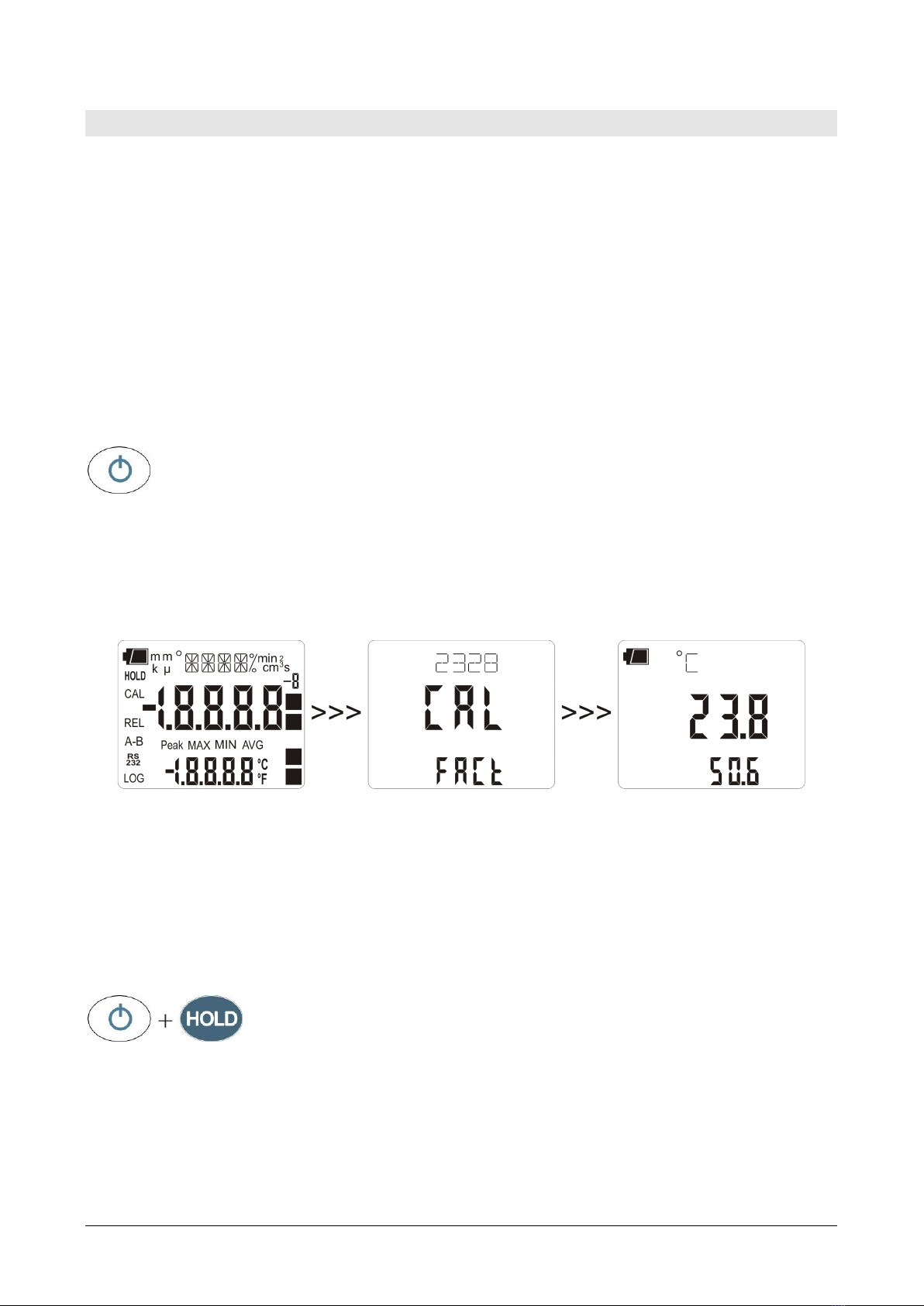
To access to the programming menu press simultaneously the DATA+(A-B) keys.
The items to be set are listed in this order:
1. Selection of the unit of measurement: the "SEL_MEAS_UNIT" message is
displayed in the comment line. The main line in the center of the display shows
the selected unit of measurement: Celsius (°C) or Fahrenheit (°F) degrees.:
•use the and arrows (respectively located above the HOLD and
REL keys) to modify the type of probe;
•press DATA/ENTER to confirm the modification and go onto the next
item;
•press CLR/ESC to cancel the modification;
•to exit the menu, press the A-B/MENU key again.
2. Selection of the type of Thermocouple: the "SEL" message is displayed in
the main line, while the type of probe is displayed in the comment line; in the
secondary line is shown the "tc" message.
The types of thermocouple that can be selected are: K, J, T, or E.
•use the and arrows (respectively located above the HOLD and
REL keys) to modify the type of thermocouple;
•press DATA/ENTER to confirm the modification and go onto the next
item;
•press CLR/ESC to cancel the modification;
•to exit the menu, press the A-B/MENU key again.
3. Starting the User calibration procedure: the ">>>_CAL_MODE" message
is displayed in the comment line, and "FACt" is displayed in the main line.
The instrument is provided with the factory ("FACt") calibration. It is also
possible to perform a "USER calibration" ("USEr")of instrument+probe. The
calibration information is saved in the instrument’s memory. The same
correction is applied to any probe connected to the input: therefore, the "USER
calibration" should only be used with the probe used for calibration and not with
other probes.
•use the and arrows (respectively located above the HOLD and REL
keys) and select USEr, to access the "USER calibration" procedure;
•press DATA/ENTER to confirm the modification;
•the "SEL_CHAN" message is displayed in the comment line;
•use the and arrows (respectively located above the HOLD and REL
keys) to select the input "A" or "B" in the main line;
•the "SEL_MEAS_1/2" message is displayed in the comment line;
•use the and arrows (respectively located above the HOLD and REL
keys) to select "0", "1" or "2" in the main line;
•press DATA/ENTER to confirm the modification;
•press CLR/ESC to cancel the modification;
•to exit the menu, press the UNIT/MENU key again.

HD2328 - 10 - V1.7
PROBES AND MEASUREMENTS
The instrument works with thermocouple probes of type K, J, T, or E.
See chapter ‘The programming menu’for the selection of the type of probe.
The contacts of the thermocouple probe connector are polarized. They must be
inserted on the standard miniature socket located on the instrument in the correct
direction. These probes are usually marked with a "+" and "–" sign.
The user can choose the unit of measurement for display of temperature: °C and °F.
The Thermometer HD2328.0 has two inputs: the temperature for input "A" (see
description of the inputs) is displayed in the main line: the temperature for input "B"
is displayed in the secondary line. When the "A-B" function is enabled, the relevant
differential temperature is displayed in the secondary line.
If two probes are used, they must be the same type of thermocouple.
TEMPERATURE MEASUREMENT
In all versions the thermocouple hot junction is housed in the end part of the probe.
The response time for the measurement of the temperature in air is greatly reduced if
the air is moving. If the air is still, stir the probe. The response times are longer than
those for liquid measurements.
The temperature measured by immersion is carried out by inserting the probe in the
liquid, in the oven where you wish to perform the measurement; the hot junction is
housed in the end part of the probe.
In the temperature measured by penetration the probe tip must be inserted into the
material; the hot junction is housed in the end part of the probe.
NOTE: when measuring the temperature on frozen blocks it is convenient to use a
mechanical tool to bore a cavity in which to insert the tip probe.
In order to perform a correct contact measurement, the measurement surface must
be even and smooth, and the probe must be perpendicular to the measurement plane.
So as to obtain the correct measurement, the insertion of a drop of oil or
heat-conductive paste between the surface and the probe is useful (do not
use water or solvents). This method also improves the response time.
CALIBRATION OF THE INSTRUMENT ON LINE WITH THE PROBE(S)
To calibrate the probes correctly, a knowledge of and abiding by the physical
phenomena on which the measurement is based is fundamental: this is the reason
why it is recommended to abide by what is reported below carefully, and only to
perform new calibrations if technically proficient and using the suitable equipment.
The instrument is provided with the only FACT (factory) calibration.
The user is also able to perform a USER calibration of instrument+probe.

HD2328 - 11 - V1.7
The calibration information is saved in the instrument's memory. The same correction
is applied to any probe that is subsequently connected to the input: therefore, the
"USER calibration" should only be used with the probe used for calibration and not
with other probes.
To pass from the user to the factory calibration and back, proceed as follows:
•press simultaneously (A-B)/MENU and DATA/ENTER to open the menu:
•press ENTER until the menu item "CAL_MODE" is selected.
•use the and arrows (respectively located above the HOLD and REL keys) to
select the type of calibration, FACT or USER;
•confirm by pressing DATA/ENTER.
CALIBRATION SEQUENCE –INSTRUMENT ON LINE WITH THE PROBE(S):
The calibration can be carried out on one or two points that should differ by at
least 10°C and be included in the probe functioning range.
1. Insert the probe into a thermostatic bath, the temperature of which is precisely
known from a reading taken on a sample reference thermometer. Wait for the
measurement to stabilize.
2. Press simultaneously (A-B)/MENU and DATA/ENTER to open the menu.
3. Press DATA/ENTER until the menu item "CAL_MODE" is selected.
4. Use the and arrows (respectively located above the HOLD and REL keys) to
select the USER calibration.
5. Confirm with DATA/ENTER.
6. Use the and arrows (respectively located above the HOLD and REL keys) to
select the input to which the probe being calibrated is connected, choosing the
upper connector A or the lower one B.
7. Confirm with DATA/ENTER.
8. The "SEL_MEAS_1/2" message is displayed in the comment line.
9. Use the and arrows to select "1" (first calibration point).
10.Confirm with DATA/ENTER.
11.The "UP DOWN 1st MEAS" message is displayed in the comment line: the
instrument display shows the measured temperature.
12.Use the and arrows to correct the indicated value until it coincides with the
value measured by the sample reference thermometer.
13.Confirm with DATA/ENTER.
14.To exit the procedure without performing the second point, select "0" and press
ENTER.
15.To calibrate the second point, select the point "2" using the and arrows.
16.Press DATA/ENTER.
17.The "UP DOWN 2nd MEAS" message is displayed in the comment line.
18.Move the probe to the second thermostatic bath and wait for the measurement to
stabilize.
19.The instrument display shows the measured temperature.
20.Use the and arrows to correct the indicated value until it coincides with the
value measured by the sample reference thermometer.
21.Confirm with DATA/ENTER.
The procedure is now complete.

HD2328 - 12 - V1.7
WARNINGS
1. Do not expose the probes to gases or liquids that could corrode the material of the
probe. Clean the probe carefully after each measurement.
2. Do not bend the probe connectors or force them upward or downward.
3. Comply with the correct polarity of the probes.
4. Do not bend or force the contacts when inserting the probe connector into the
instrument.
5. Do not bend, deform or drop the probes, as this could cause irreparable damage.
6. Always select the most suitable probe for your application.
7. In general, do not use temperature probes in presence of corrosive gases or
liquids; the probe external containers are made of AISI 316 or INCONEL stainless
steel, while the contact probe containers are made from AISI 316 or INCONEL
stainless steel plus silver. Avoid contact between the probe surface and any sticky
surface or product that could corrode or damage it.
8. To obtain reliable measurements, temperature variations that are too rapid must
be avoided.
9. Temperature probes for surface measurements (contact probes) must be held
perpendicular against the surface. Apply oil or heat-conductive paste between the
surface and the probe in order to improve contact and reduce reading time.
Whatever you do, do not use water or solvent for this purpose. A contact
measurement is always very hard to perform. It has high levels of uncertainty and
depends on the ability of the operator.
10.Temperature measurements on non-metal surfaces usually require a great deal of
time due to the low heat conductivity of non-metal materials.
11.The sensor is not insulated from its external casing; be very careful not to come
into contact with live parts (above 48V). This could be extremely
dangerous for the instrument as well as for the operator, who could be
electrocuted.
12.Avoid taking measurements in presence of high frequency sources, microwave
ovens or large magnetic fields; results may not be very reliable.
13.The instrument is water resistant, but should not be immersed in water. Should
the instrument fall into the water, check for any water infiltration from the
connectors' side. Gently handle the instrument in such a way as to prevent any
water infiltration from the connectors' side.

HD2328 - 13 - V1.7
INSTRUMENT SIGNALS AND FAULTS
The following table lists all error indications and information displayed by the
instrument and supplied to the user in different operating situations:
Display indications
Explanation
1ST_MEAS UP DOWN
Correct the first point using the arrows
/
2ND_MEAS UP DOWN
Correct the second point using the arrows
/
BATT TOO LOW
CHNG NOW
Indication of insufficient battery charge appearing on
turning on. The instrument issues a long beep and turns
off. Replace the batteries.
BURN
The probe is disconnected or faulty.
CAL
LOST
Program error: it appears after turning on for a few
seconds. Contact the instrument's supplier.
CAL FACT
Factory calibration.
CAL USER
User calibration.
CAL_MODE
Calibration mode
ERR
This message appears when a wrong function is called:
for example, should the A-B key be pressed or the AVG
function be enabled when one of the two probes is not
connected.
FUNC CLRD
Max, min and average values clearing
OVER o UNDR
Measurement overflow: indicates that the probe is
measuring a value exceeding the measuring range.
PLS_EXIT >>> FUNC
RES_FOR_FACT ONLY
Please exit using ESC >>> function reserved to factory
calibration
SEL CHAN
Input channel selection
SEL MEAS 1/2
Select the first/second calibration point
SEAL MEAS UNIT
Selection of the unit of measurement
SEAL_TYPE_TC
Selection of the type of thermocouple
SYS
ERR
#
Instrument management program error. Contact the
instrument's supplier and communicate the numeric code
# reported by the display.
INSTRUMENT STORAGE
Instrument storage conditions:
•Temperature: -25…+65°C.
•Humidity: less than 90%RH without condensation.
•Do not store the instrument in places where:
•humidity is high;
•the instrument may be exposed to direct sunlight;
•the instrument may be exposed to a source of high temperature;
•the instrument may be exposed to strong vibrations;
•the instrument may be exposed to steam, salt or any corrosive gas.
The instrument case is made of ABS plastic: do not use any incompatible solvent for
cleaning.

HD2328 - 14 - V1.7
LOW BATTERY WARNING AND BATTERY REPLACEMENT
The battery symbol
on the display constantly shows the battery charge status. To the extent that batteries
have discharged, the symbol "empties". When the charge decreases still further it
starts blinking.
In this case, batteries should be replaced as soon as possible.
If you continue to use it, the instrument can no longer ensure correct measurement.
The memory data are maintained.
If the battery charge level is insufficient, the following message appears
when you turn the instrument on:
BATT TOO LOW
CHNG NOW
The instrument issues a long beep and turns off. In this case, replace the
batteries in order to turn the instrument back on.
To replace the batteries, proceed as follows:
1. switch the instrument off;
2. unscrew the battery cover counter clockwise;
3. replace the batteries (3 1.5V alkaline batteries - type AA);
4. screw the cover on clockwise.
Malfunctioning upon turning on after battery replacement
After replacing the batteries, the instrument may not restart correctly; in this case,
repeat the operation.
After disconnecting the batteries, wait a few minutes in order to allow circuit
condensers to discharge completely; then reinsert the batteries.
WARNING ABOUT BATTERY USE
•Batteries should be removed when the instrument is not used for an extended
time.
•Flat batteries must be replaced immediately.
•Avoid batteries leaking.
•Always use good quality leakproof alkaline batteries. Sometimes on the market,
it is possible to find new batteries with an insufficient charge capacity.

HD2328 - 15 - V1.7
NOTES ABOUT WORKING AND OPERATIVE SAFETY
Authorized use
The technical specifications as given in chapter “TECHNICAL CHARACTERISTICS” must
be observed. Only the operation and running of the measuring instrument according
to the instructions given in this operating manual is authorized. Any other use is
considered unauthorized.
General safety instructions
This measuring system is constructed and tested in compliance with the EN 61010-1
safety regulations for electronic measuring instruments. It left the factory in a safe
and secure technical condition.
The smooth functioning and operational safety of the measuring system can only be
guaranteed if the generally applicable safety measures and the specific safety
instructions in this operating manual are followed during operation.
The smooth functioning and operational safety of the instrument can only be
guaranteed under the environmental and electrical operating conditions that are in
specified in chapter TECHNICAL CHARACTERISTICS.
Do not use or store the product in places such as listed below:
•Rapid changes in ambient temperature which may cause condensation.
•Corrosive or inflammable gases.
•Direct vibration or shock to the instrument.
•Excessive induction noise, static electricity, magnetic fields or noise.
If the measuring system was transported from a cold environment to a warm
environment, the formation of condensate can impair the functioning of the measuring
system. In this event, wait until the temperature of the measuring system reaches
room temperature before putting the measuring system back into operation.
Obligations of the purchaser
The purchaser of this measuring system must ensure that the following laws and
guidelines are observed when using dangerous substances:
EEC directives for protective labour legislation
National protective labour legislation
Safety regulations

HD2328 - 16 - V1.7
INSTRUMENT TECHNICAL CHARACTERISTICS
Instrument
Dimensions (Length x Width x Height) 140 x 88 x 38 mm
Weight 160 g (complete with batteries)
Material ABS
Display 2x4½ digits plus symbols
Visible area: 52 x 42 mm
Operating conditions
Operating temperature -5…+50°C
Warehouse temperature -25…+65°C
Working relative humidity 0…90% RH without condensation
Protection degree IP67
Power
Batteries 3 1.5V type AA batteries
Autonomy 200 hours with 1800mAh alkaline
batteries
Power absorbed with instrument off < 20 µA
Connections
Inputs for probes 2-pole female polarized standard
miniature connectors
Unit of Measurement °C - °F;
Measurement of temperature by Instrument
Tc measurement range: K -200 … +1370°C
Tc measurement range: J -100 … +750°C
Tc measurement range: T -200 … +400°C
Tc measurement range: E -200 … +750°C
Resolution 0.1°C
Instrument accuracy
Thermocouple K ±0.1 °C up to 600 °C
±0.2 °C over 600 °C
Thermocouple J ±0.1 °C up to 400 °C
±0.2 °C over 400 °C
Thermocouple T ±0.1 °C
Thermocouple E ±0.1 °C up to 300 °C
±0.2 °C over 300 °C
The precision only refers to the instrument. Error due to the thermocouple or
to the cold junction reference sensor is not included.
Temperature drift @20°C 0.02%/°C
Drift after 1 year 0.1°C/year
Accuracy of the thermocouple probes:

HD2328 - 17 - V1.7
The tolerance of a type of thermocouple corresponds to the maximum acceptable
departure from the e.m.f. of any thermocouple of that type, with reference junction at
0°C.
The tolerance is expressed in degrees Celsius, preceded by the sign.
The percentage tolerance is given by the ratio between the tolerance expressed in
degrees Celsius and the measurement junction temperature, multiplied by one
hundred.
The thermocouples conforming to regulations must comply with one of the following
tolerance levels, the values of which are reported in the table.
G I (special tolerances)
G II (normal tolerances)
The tolerances refer to the expected thermocouple operating temperature, in
agreement with the thermoelements' diameter.
Tolerance of the thermocouples:
Type of
themocouple
Range °C G I* G II*
K
0 … +1370°C
±1.1°C or ±0.4%
±2.2°C or ±0.75%
J
0 … +750°C
±1.1°C or ±0.4%
±2.2°C or ±0.75%
T
0 … +400°C
±0.5°C or ±0.4%
±1°C or ±0.75%
E
0 … +750°C
±1°C or ±0.4%
±1.7°C or ±0.5%
K**
-200 … 0°C
---
±2.2°C or ±2%
T**
-200 … 0°C
---
±1°C or ±1.5%
E**
-200 … 0°C
---
±1.7°C or ±1%
* The higher of the two optional limits is the valid one. Example: at 200°C the
percentage tolerance for type K thermocouple, tolerance G II, is ±0.75% and is equal
to ±1.5°C. Therefore, the limit of ±2.2°C is valid. On the other hand, at 600°C the
percentage tolerance is equal to ±4.5°C, and therefore this is the limit to use.
** The thermocouples that meet the limits for temperatures higher than 0°C do not
necessarily meet the limits for the range under 0°C.

HD2328 - 18 - V1.7
ORDERING CODES
HD2307.0 The kit is composed of the HD2328.0 with two inputs, 3 1.5V
alkaline batteries, operating manual, and case. The probes
must be ordered separately.
THERMOCOUPLE PROBES
The thermocouple probes can be connected to all instruments using the standard
miniature connector, which can be obtained from the price list.
DELTA OHM metrology laboratories LAT N° 124 are ISO/IEC 17025
accredited by ACCREDIA for Temperature, Humidity, Pressure, Photometry /
Radiometry, Acoustics and Air Velocity. They can supply calibration
certificates for the accredited quantities.


GHM GROUP – Delta OHM | Delta Ohm S.r.l. a socio unico
Via Marconi 5 | 35030 Caselle di Selvazzano | Padova | ITALY
Phone +39 049 8977150 | Fax +39 049 635596
www.deltaohm.com | sales@deltaohm.com
WARRANTY
Delta OHM is required to respond to the "factory warranty" only in those cases provided by
Legislative Decree 6 September 2005 - n. 206. Each instrument is sold after rigorous inspections;
if any manufacturing defect is found, it is necessary to contact the distributor where the
instrument was purchased from. During the warranty period (24 months from the date of invoice)
any manufacturing defects found will be repaired free of charge. Misuse, wear, neglect, lack or
inefficient maintenance as well as theft and damage during transport are excluded. Warranty does
not apply if changes, tampering or unauthorized repairs are made on the product. Solutions,
probes, electrodes and microphones are not guaranteed as the improper use, even for a few
minutes, may cause irreparable damages.
Delta OHM repairs the products that show defects of construction in accordance with the terms and
conditions of warranty included in the manual of the product. For any dispute, the competent court
is the Court of Padua. The Italian law and the “Convention on Contracts for the International Sales
of Goods” apply.
TECHNICAL INFORMATION
The quality level of our instruments is the result of the continuous product development. This may
lead to differences between the information reported in the manual and the instrument you have
purchased. In case of discrepancies and/or inconsistencies, please write to sales@deltaohm.com.
Delta OHM reserves the right to change technical specifications and dimensions to fit the
product requirements without prior notice.
DISPOSAL INFORMATION
Electrical and electronic equipment marked with specific symbol in compliance
with 2012/19/EU Directive must be disposed of separately from household
waste. European users can hand them over to the dealer or to the manufacturer
when purchasing a ne
w electrical and electronic equipment, or to a WEEE
collection point designated by local authorities. Illegal disposal is punished by
law.
Disposing of electrical and electronic equipment separately from normal waste helps to
preserve natural resources and allows materials to be recycled in an environmentally friendly
way without risks to human health.
V1.7
07/05/2021
Other manuals for Delta OHM HD2328.0
1
Table of contents
Other GHM Thermometer manuals

GHM
GHM GREISINGER G 1700 Series Installation instructions

GHM
GHM Greisinger GTH 2448/2 User manual

GHM
GHM GREISINGER G 1202 Installation instructions

GHM
GHM GREISINGER GTH 2448 / 1 User manual

GHM
GHM Greisinger G 1200 Installation instructions

GHM
GHM GTH 2448/4 User manual

GHM
GHM Delta OHM HD2328.0 User manual

GHM
GHM Delta OHM HD2108.1 User manual

GHM
GHM GREISINGER G 1730 User manual

GHM
GHM GREISINGER GTH 1150 User manual