manuals.online logo
Brands
  1. Home
  2. •
  3. Brands
  4. •
  5. Gianni Industries
  6. •
  7. Door Lock
  8. •
  9. Gianni Industries Indoor Series User manual

Gianni Industries Indoor Series User manual

Electromagnetic Lock
(Indoor Series)
Installation Instruction
Optional Bracket
Regular Installation L-bracket for narrow
frame (optional) U-bracket for frameless
glass door (optional) LZ-bracket for inswing
door (optional)
Bracket installation is according to door swing direction and door frame type ,e. g. narrow frame door , frameless glass door, inswing door , etc.
Regular Installation
1
2
3
Templ ate
Fold the mounting template 90°
Place the template to the proper
position of the door and frame. Mark
the hole positions of the template on
the door and frame.
Drill the holes according to the
marks.
7
Fix the mounting plate on the door
with mounting screws
Cable
8
Use the Allen wrench and fixing bolts
to tighten the electromagnetic lock to
mounting plate.
Allen wrench
9
Connect the power and test the unit.
Outdoor
Power
6
Fasten the mounting plate with the
mounting screws. The position of the
mounting plate should be adjustable.
5
Th e ru b b e r w a s h e r mak es t h e
s u r f a c e of th e a r m a t u r e pl a t e
adjustable in order to completely fit
the surface of magnetic lock.
Rubber Washer
(outswing door)
Copyright © Gianni Industries, Inc. All rights reserved.
P-MU-AM-EM Ver. I Published on: 2011.04.07
4
Please install the armature plate as
illustrated here. (Dimensions of the
holes are depending on the door
types as illustrated below.)
Armature Plate
Recommendation:
For Micro EM-locks (300 LBS), maximum thickness of door is 44 mm.
For Mini EM-locks (600 LBS), maximum thickness of door is 50 mm.
For Midi EM-locks (800 LBS), maximum thickness of door is 48 mm.
For Maxi EM-locks (1200 LBS), maximum thickness of door is 46 mm.
Drill a Ø8mm hole thrugh
d o o r o n c l o s i n g s i d e
enlarge to Ø 12.7mm, by a
sexnut blot on the opening
side. The depth is 36mm.
12.7mm 8mm
Hollow Metal Door
6.8mm for M8-1.25 thread
Reinforced Door
12.7mm 8mm
Solid Door
36mm
Outdoor Outdoor
Outdoor
Drill a
and tap on closing side
a M8x12.5 thread.
Ø6.8mm hole
Drill a
d o o r, o n c l o s i n g s i d e
enlarge to Ø12.7mm by a
sexnut blot on the opening
side.
Ø8mm hole through
LZ bracket for Inswing doors
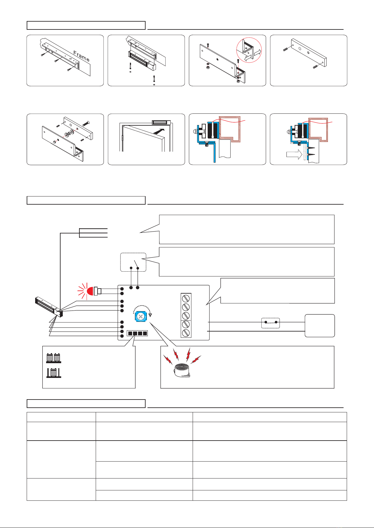
Connecting Diagram
+
+
-
-
N.O.
COM.
N.C.
Power
Input
Power
supply
Trigger
SPDT relay
0.5A/125VAC
1A/24VDC
LED indicator
GREEN: Open
RED : Locked
NO LED: No power
Sensor input
Timer Adjustment
Shorten
12VDC
24VDC
Voltage Selection jumpers
Check jumper settings before
connecting the lock to 24 VDC
input power. Damage to the
lock may result from incorrect
jumper settings.
Bond sensor output (optional)
Control Device N.C. contact or Access Relay
Buzzer Alarm
Door Held Open Alarm is an auditory feedback for users.
Alarm sounds when the door is not closed for over a
specified time limit. VR timer (Timer Adjustment) is
adjustable from 1 to 20 seconds.
Ensures the automatic lock mode after the door is closed properly and it
can be adjusted from 1 to 80 seconds. (Timer Adjustment)
Models: 10001TD , 10002TD , 10010TD, 10020TD,10060TD,10040TD
Door Status Sensor indicates the door is in an opened or closed
status.
Models: 10002DS , 10020DS , 10040DS
Reed switch rated 0.2A/12VDC
Relock time delay
(Optional)
Door Status Sensor
(Optional)
N.O.
Com.
N.C.
Orange:
White:
Brown:
Problem Possible Cause Solution
Door does not lock No power
Poor contact between electromagnet and
armature plate
Low voltage or incorrect voltage setting
A secondary diode was installed across
the electromagnetic lock
Misalignment between the armature plate
and electromagnetic lock
Make sure the wires are connected properly
Check that the power supply is connected and works properly
Make sure the lock switch is wired correctly (N.C.)
Make sure if the armature plate is deformed
Make sure the contact surfaces of the electromagnet and armature plate are clean
and free from dust
Make sure the armature plate and electromagnetic lock are aligned correctly
Make sure if the rubber washer was used between the bracket lock and armature plate
Check the electromagnet lock is set for the correct voltage.
Check the voltage at the of input electromagnetic locks. If low, determine if the
correct wire gauge is being used to prevent excessive voltage drop.
Remove any diode installed across the magnet for "spike"
suppression. (The magnet is fitted with a metal oxide varistor to prevent back EMF)
Low holding force
Sensor output is not functioning
Trouble Shooting
2
Use the fixing bolt to tighten the
electromagnetic lock on L bracket.
1
Find a mounting location on the
door frame for the L bracket. Make
sure that the door is still closeable.
6
Close the door and connect the
power.
4
Insert the guide pins into the
armature plate.
5
3
N.C. contact output: open status
N.O. contact output: locked status
Relay rating output needs to meet the instruction of PCB
7Power
Outdoor
Finish Power
Outdoor
Assemble the Z bracket, and
make sure that the position of the
Z bracket is adjustable.
Fasten the armature plate to the
Z bracket (Rubber washer must
be added)
After the maglock attracts the
a r m a t u r e p la t e , a d j u s t the
position between Z bracket and
the door. Then fix the Z bracket.
Connect the power, close the
door and test the unit.
Copyright © Gianni Industries, Inc. All rights reserved.
P-MU-AM-EM Ver. I Published on: 2011.04.07

Other Gianni Industries Door Lock manuals

Gianni Industries NH-Indoor Series User manual

Gianni Industries

Gianni Industries NH-Indoor Series User manual

Gianni Industries GK320 Series User manual

Gianni Industries

Gianni Industries GK320 Series User manual

Popular Door Lock manuals by other brands

Yale Smart Latch 2 installation guide

Yale

Yale Smart Latch 2 installation guide

Homematic IP HmIP-DLD Mounting instruction and operating manual

Homematic IP

Homematic IP HmIP-DLD Mounting instruction and operating manual

Philips EasyKey DDL702 user manual

Philips

Philips EasyKey DDL702 user manual

Cobra MPC  SERIES Installation & programming guide

Cobra

Cobra MPC SERIES Installation & programming guide

DynaLock 3101B installation instructions

DynaLock

DynaLock 3101B installation instructions

Prime-Line E-2402 manual

Prime-Line

Prime-Line E-2402 manual

Igloohome OE1 Installer/user guide

Igloohome

Igloohome OE1 Installer/user guide

Major Manufacturing HIT-41 SERIES instructions

Major Manufacturing

Major Manufacturing HIT-41 SERIES instructions

Kwikset Kevo Installation and user guide

Kwikset

Kwikset Kevo Installation and user guide

LSDA R/V installation instructions

LSDA

LSDA R/V installation instructions

INSYS EloStar time user manual

INSYS

INSYS EloStar time user manual

Glutz PIATTO Fixing instructions

Glutz

Glutz PIATTO Fixing instructions

Kaba E-Plex 5x00 Cylindrical installation instructions

Kaba

Kaba E-Plex 5x00 Cylindrical installation instructions

CEStronics Omega Flex quick guide

CEStronics

CEStronics Omega Flex quick guide

SOMFY Badge Reader manual

SOMFY

SOMFY Badge Reader manual

Cal-Royal SDLP-RND-ADA installation manual

Cal-Royal

Cal-Royal SDLP-RND-ADA installation manual

IULOCK IU-20 Installation and user guide

IULOCK

IULOCK IU-20 Installation and user guide

PDQ KMS pdqSMART Installation instruction

PDQ

PDQ KMS pdqSMART Installation instruction

manuals.online logo
manuals.online logoBrands
  • About & Mission
  • Contact us
  • Privacy Policy
  • Terms and Conditions

Copyright 2025 Manuals.Online. All Rights Reserved.