Gilson SS-10 User manual

OPERATING MANUAL
1-Touch Vibratory Sieve Shaker
SS-10
04/16/2010
PHONE: 800-444-1508 P.O. Box 200, Lewis Center, Ohio 43035-0200 FAX: 800-255-5314
740-548-7298 E-mail: customerservice@gilsonco.com Website: www.globalgilson.com 740-548-5314

Gilson Company, Inc. 1-Touch Vibratory Sieve Shaker: SS-10
Page 2
You are responsible for the safe operation of this Sieve Shaker, and maintaining this
equipment in compliance with these instructions. You must read and completely un-
derstand these operating and safety instructions before using this machine.
1. The 1-Touch Vibratory Sieve Shaker is configured to operate on 115V/60Hz
power supplies, as noted on the specification tag. This unit is NOT explosion-
proof.
2. ALWAYS check electrical wiring for loose connections and for pinched or frayed
wiring.
3. ALWAYS use a properly configured three-pronged plug, as supplied with the
unit. Connect the machine to a properly-wired, three-pronged receptacle. Make
sure the cord is routed safely.
4. ALWAYS disconnect and lock-out power supply before performing maintenance
and repairs.
5. NEVER operate the sieve shaker without having all covers and case in place.
6. ALWAYS unplug or disconnect machine from the power source when the unit is
not in operation.
DANGER!: This machine operates on electric current. Improper operation
could result in electric shock, electrocution, or an explosion.
SAFETY INSTRUCTIONS

Gilson Company, Inc. 1-Touch Vibratory Sieve Shaker: SS-10
Page 3
Table of Contents
Page
Safety Instructions 2
1.0 Uncrating & Assembly Instructions 4
2.0 Preface 4
3.0 Clamping System 5
4.0 Touch Screen Operation 6
4.1 Test Time 6
4.2 Interval & Pause Time 7
4.3 Power Level 8
4.4 Test ID 8
4.5 Lock/Unlock Screen Button 8
4.6 Start/Stop & Pause/Resume Buttons 9
5.0 Parts Diagram 10
6.0 Parts List 11
7.0 Gilson Sieves 12
8.0 Test Sieve Verification & Services 13
9.0 8in Diameter ASTM Test Sieves 15

Gilson Company, Inc. 1-Touch Vibratory Sieve Shaker: SS-10
Page 4
1.0 UNCRATING & ASSEMBLY INSTRUCTIONS
2.0 PREFACE
1. The SS-10 weighs approximately 90lb (40kg). Use
appropriate equipment and manpower to uncrate the
sieve shaker. Wear safety glasses and work gloves.
2. Examine the shipping carton for signs of damage before
opening. Report damage to the shipper immediately.
Leave the carton as intact as possible to facilitate return
shipping, if necessary.
3. Lift the Base Assembly (Item (1). See the Exploded
Diagram on pg. 10) from the carton, and position it on
a solid, level work surface. Examine the unit again for
damage that may have been concealed.
4. The plastic Clearance Spacer (2) is secured for ship-
ping to the top of the SS-10 Base Assembly with three
1/4-20 x 1.75 stainless steel flat-head screws (4). Us-
ing the included Allen key wrench, remove the three
screws and set aside. Leave the spacer on top of the
base assembly.
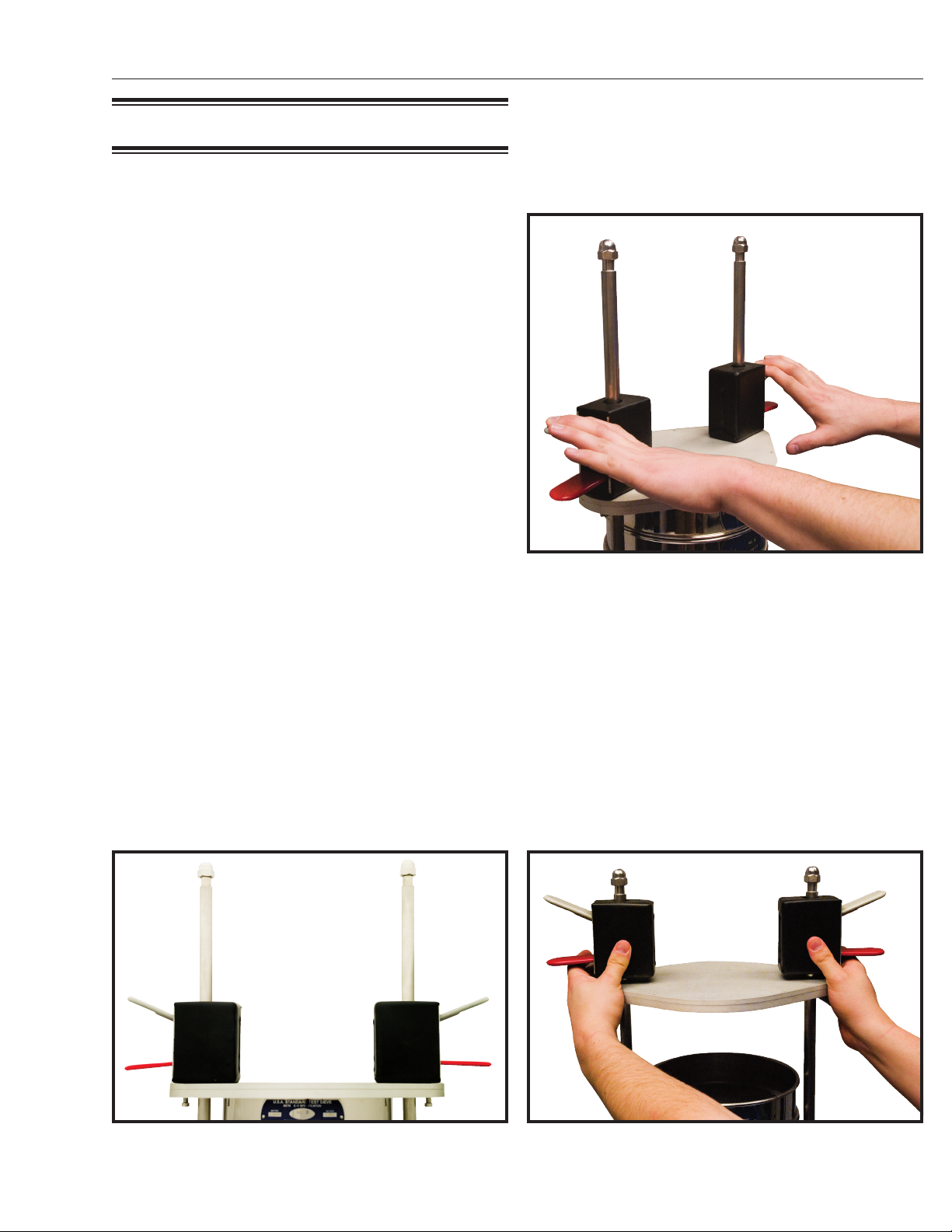
5. The Sieve Stack Assembly includes the two Clamp Rods
(5), bottom and top Covers (3 and 6), Clamps (9), and
top and base Gaskets (12 and 13), shipped partially
assembled. To complete assembly, rotate the Clamps
so that the tabs are facing outward. Slide the Top Cover
Plate up and secure it to the clamps by installing the
10-32 x 1 Shoulder Bolts (10) through the bottom of
the plate into the threaded holes in the bottom of each
clamp. Tighten Securely.
6. Place the Sieve Stack Assembly on top of the plastic
Clearance Spacer, aligning the three holes in the spacer
and base plate with the threaded holes in the top of the
base assembly. Install the three stainless steel flat-head
screws, and tighten securely.
7. Install the Base Gasket (13) into the recess in the Bot-
tom Cover (3).
8. Move the assembled SS-10 into place on a solid, sub-
stantial, and level work surface capable of supporting
the machine during operation.
9. Insert the female end of the included power cord into
the power connection on the back of the SS-10. Power
ON/OFF is controlled by the rocker switch adjacent to
this connection.
Gilson’s new 1-Touch Vibratory Sieve Shaker for 8in and
200mm sieves combines the latest in electronic control with
proven particle sizing technology for fast, accurate separa-
tions. Three-dimensional sieving action evenly distributes
and continuously reorients particles across the mesh sur-
face to insure optimum sieving performance. The SS-10 is
suitable for a variety of materials with particle sizes from
No.10 (2mm) to No.635 (20µm). Fast-acting sieve clamps
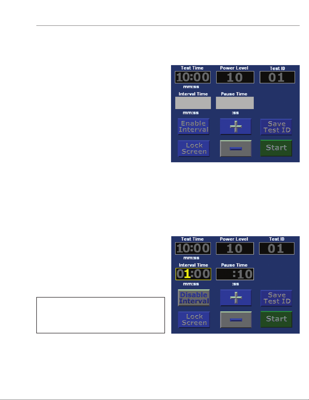
adjust quickly with little effort. Power level, sieving time
and interval pauses are all controlled and programmed on
the touch screen. Up to 99 testing profiles can be stored in
memory to insure exact repeatability.

Gilson Company, Inc. 1-Touch Vibratory Sieve Shaker: SS-10
Page 5
3.0 CLAMPING SYSTEM
Gilson sieve clamps are designed for efficiency, ease of use,
and rugged dependability. They allow fast, easy insertion
and removal of sieve stacks, while insuring that sieves are
tightly secured in place during testing. Considerable time
and effort is saved over conventional clamping systems,
especially when processing multiple samples.
DO NOT lubricate the guide rods or internal contact surfaces
of the clamps. If slippage occurs during operation, clean
and degrease, then lightly sand the guide rods.
Each clamp has two levers; the bottom is red and the top one
is light gray (see Figure 3.1). To rapidly reposition the stack
cover on the guide rods, maintain slight upward pressure
on both the red levers at once while sliding the clamps up
or down. When moving the stack cover, keep the clamps
at an even height to prevent binding. Once the cover is at
the desired position, release pressure on the levers and the
cover will stay in place.
Once the stack cover is seated over the top of the sieve
stack, press downward on the gray levers several times
until sufficient pressure is applied to clamp the stack tightly
(see Figure 3.2).
To release the stack, lift up on both red levers simultane-
ously. Slide the cover up slightly to clear the top of the
sieve stack. Once the cover is out of the way, release the
pressure on the red levers (see Figure 3.3).
SS-10 Clamps
Figure 3.1
Clamping down the sieve stack
Figure 3.2
Releasing the stack of clamped sieves
Figure 3.3

Gilson Company, Inc. 1-Touch Vibratory Sieve Shaker: SS-10
Page 6
4.0 TOUCH SCREEN OPERATION
Inputting data on the Touch Screen is as simple as pressing
the designated area with your finger. A gentle, momentary
pressure usually works better than a hard push with the fin-
ger. Using other objects on the screen is not recommended
and may damage the screen, voiding the warranty.
The Touch Screen is used both to input and display informa-
tion controlling operation of the SS-10 Shaker:
• ThefiveupperdisplaysshowTest Time, Power Level,
Interval Time, Pause Time, and Test ID.
• Thesixlowersectionsfunctionascontrolbuttonsto
start or stop a test cycle, enable or disable vibration
intervals, lock the screen, and select a test ID. The +
and – buttons are used to input values for the various
fields (see Figure 4.0).
NOTE: The Touch-Screen display is not moisture-
resistant. Avoid the use of liquids in its vicinity and use
caution when cleaning the display. Moisture damage
to the Touch-Screen is not covered by warranty.
4.1 Test Time
Test Time is the amount of time the sample will be actively
vibrated. It is a count-down timer adjustable from 00:00 to
99:59 minutes:seconds. When the timer reaches zero, the
unit will stop vibrating and beep.
Editing the Test Time Display:
To adjust, press the Test Time display once. The outline
and numbers inside turn yellow and the first digit will flash
(see Figure 4.1). The flashing digit is adjusted using the +/-
buttons. Once adjusted to the desired value, press the Test
Time display again. The next digit will begin to flash and is
now adjustable with the +/- buttons. Continue until all the
Test Time digits are set. When changes are complete, press
the Test Time display box once while the last digit is flashing
to accept the changes and return the screen to idle.
NOTE: Pressing the touch screen anywhere other
than the Test Time box, or the +/- buttons at any time
during editing will quickly accept any changes made,
and return the screen to idle.
SS-10 Touch Screen
Figure 4.0
Editing the Test Time Display
Figure 4.1

Gilson Company, Inc. 1-Touch Vibratory Sieve Shaker: SS-10
Page 7
4.2 Interval & Pause Time
The Interval feature allows timed pauses to be introduced
into cycles of active vibration. Separation of some materials
is improved by interruptions in the vibration cycle that
promote particle reorientation. Optimization of interval and
pause times is usually determined experimentally for a
given material.
• Interval Time refers to the period of active vibration
between pauses, and Pause Time is the time that the
unit is not vibrating. Both take place within the period
specified by the Test Time setting.
• The Interval feature is toggled on and off using the
Enable/Disable Interval button. When disabled, the
Interval Time and Pause Time displays are solid grey
and the Enable Interval button is displayed (see Figure
4.2.1). When enabled, the Interval Time and Pause Time
boxes, display settable digits and the Disable Interval
button is displayed. Editing the Interval time is similar
to editing the Test Time.
• WiththeIntervalfeatureenabled,timesmustbeentered
in the Interval Time and Pause Time displays. Interval
times can be any value up to the period selected for
Total Time, and typically range from a few seconds
to a few minutes in length. Pause times are typically
only a few seconds, but can be set up to 99 seconds,
if desired.
Editing the Interval Time & Pause Time Displays:
Enable the Interval button. Press the display box of the
Interval Time or Pause Time box once. The outline and
numbers inside turn yellow and the first digit will flash (see
Figure 4.2.2). The flashing digit is adjusted by pressing
the +/- buttons. Once adjusted to the desired value, press
the display box again. The next digit will begin to flash and
is now adjustable with the +/- buttons. Continue until you
have all the digits set. Pressing the display box once while
the last digit is flashing accepts the changes and returns
the screen to idle.
NOTE: Pressing the touch screen anywhere other
than the edited display box or the +/- buttons at any
time during editing will quickly accept any changes
made, and return the screen to idle.
Interval & Pause Time
Figure 4.2.1
Editing the Interval Time & Pause Time Displays
Figure 4.2.2

Gilson Company, Inc. 1-Touch Vibratory Sieve Shaker: SS-10
Page 8
4.3 Power Level
Power Level is the amount of vibration produced by the unit.
Vibration intensity on a relative scale between 1 (low) and
10 (high) can be selected. Actual vibration amplitude and
acceleration forces on the specimen particles will vary and
are influenced by the bulk density and total mass of the
sample, as well as the height of the sieve stack.
Editing Power Level Settings:
Press the Power Level box once. The outline, units of
measure and title of the box will turn yellow and begin to
flash (see Figure 4.3). Pressing the +/- buttons will adjust
the value. The selectable values range from 1 (Low) to
10 (High) on a relative scale. When the desired value is
displayed, press the display again to accept.
NOTE: Pressing the touch screen anywhere other than
the edited display box or the +/- buttons at any time
during editing will quickly accept any changes made,
and return the screen to idle.
Editing Power Level Settings
Figure 4.3
4.4 Test ID
The Test ID display and the Save/Delete Test ID toggle
button are used to save and retrieve display settings. The
Test ID display shows the current selected location, from
0 to 99. If nothing has been saved in that location, zeros
are displayed, and the blue Save Test ID button is shown.
If values are already stored at this location, they will be
displayed and the red Delete Test ID button will be shown.
Pressing Delete will remove stored information. The display
does not change until new data is entered.
To create a new ID, start at a location that has no data
stored in it, or delete stored values to clear the memory
space. Press the Test ID display box. The outline and first
digit will turn yellow and flash. Set the value using the +/-
buttons and press the display again. Repeat the process
to set the second digit and press to save the test ID loca-
tion. Proceed to the other locations and set the values as
described above. When done, press the blue Save Test ID
button to save all information at that location.
4.5 Lock/Unlock Screen Button
The Lock/Unlock Screen button protects against unin-
tentional changes to the settings. To activate, press the
blue Lock Screen button. The button will then change to
display Unlock Screen. When the screen is locked, only
the Start/Stop and Unlock buttons function. When the
screen is unlocked, all buttons can be used to adjust and
save values.

Gilson Company, Inc. 1-Touch Vibratory Sieve Shaker: SS-10
Page 9
4.6 Start/Stop & Pause/Resume Buttons
The Start/Stop button controls the test cycle. Pressing the
green Start button activates vibration and the count-down
timer to the selected values. Pressing the red Stop button
stops the machine immediately and resets the timer. Once
started, the Save/Delete Test ID button is converted into a
Pause/Resume button. Pressing Pause temporarily halts
the test cycle and timer. Pressing Resume continues the
test at the time remaining.
The SS-10 accepts up to eight full-height or sixteen half-
height round test sieves of 8in (203mm) or 200mm diameter
plus pan. Note that 8in and 200mm sieves cannot be
used in the same stack.
The SS-10 can test a wide variety of materials. Because
of differing characteristics of these materials, optimum
combinations of power levels, test times and interval times
must be determined experimentally. Low initial power and
time settings are recommended when testing an unfamiliar
material. Settings may be increased gradually until complete
separation is achieved without physically degrading the mate-
rial. Complete separation can be assumed when additional
one minute increments of operation at higher power levels
produce less than 1% of total weight difference in material
passing a given sieve.
In addition to material type, power input and time, differ-
ences in sieve stack height and specimen weights may also
cause performance variations. Using similar sieves, stack
heights and sample weights will help maintain consistent
separation results.
NOTE: Occasionally, the unit may exhibit a pronounced
rhythmic surging of the vibration level during opera-
tion. This can be prevented by stopping the machine
and resetting the power level, changing the number
of sieves in the stack, or changing the weight of the
specimen.
Start/Stop & Pause/Resume Buttons
Figure 4.6

Gilson Company, Inc. 1-Touch Vibratory Sieve Shaker: SS-10
Page 10
5.0 PARTS DIAGRAM
PARTS DIAGRAM

Gilson Company, Inc. 1-Touch Vibratory Sieve Shaker: SS-10
Page 11
6.0 PARTS LIST
Item
No. Part No. No.
Req’d Description
1 WGV8-BASE_ASSY 1 Base Assembly
2 WGV8-SPACER 1 Clearance Spacer
3 WGV8-BOTTOM_COVER_ASSY 1 Bottom Cover Assembly
4 WGSW-252175FAMSS 3 1/4-20 x 1.75 Flat Head Allen (Stainless)
5 WGV8-CLAMP_ROD 2 Clamp Rod
6 WGV8-TOP_COVER_ASSY 1 Top Cover Assembly
7 WGNT-513ACNOSS 2 1/2-13 Acorn Nut (Stainless)
8 WGNT-513HJNOSS 2 1/2-13 Hex Jam Nut (Stainless)
9 WGSC-CLAMP 2 Sieve Clamp
10 WGSW-SB-03210025CSNSS 2 Shoulder Bolt 10-32 x 1in
11 WGAS-PP-SK0129 1 Power Cord
12 WGV8-TOP_PLATE_GASKET 1 Top Base Plate Gasket
13 WGV8-PLATE_GASKET 1 Base Plate Gasket
14 WGUS-1-1/2" FOOT 4 1-1/2in Rubber Foot

Gilson Company, Inc. 1-Touch Vibratory Sieve Shaker: SS-10
Page 12
7.0 GILSON SIEVES
Gilson stocks the widest range and largest quantity of sieves
of any major supplier. Immediate shipment is available for
all popular sizes. Custom sieves with special diameters and
stacking heights are also available.
ASTM Sieves meet the requirements of ASTM E 11. ISO
Sieves meet ISO 565 specifications with tolerances to
ISO 3310-1. All are serial numbered and supplied with a
certificate of manufacturing conformance.
ASTM and ISO Test Sieves are categorized in three different
classes.
• Compliance Test Sieves are supplied with a basic
certificate of manufacturing conformance. All Gilson Test
Sieves meet Compliance grade requirements.
• Inspection Test Sieves have a specified number of
openings measured and reported for each sieve.
• CalibrationTestSieves have two to three times as many
openings measured on each sieve, and are supplied with
more detailed documentation.
Mesh Opening Sizes are listed using standard millimeter
(mm) or micrometer (µm) descriptions, as well as traditional
inch and number designations where appropriate. Gilson
offers all mesh sizes, but not all sizes are available in
every frame diameter. Common coarse sizes are also
listed. Normally, every second or fourth size is used,
although precision testing may require consecutive sizes.
Additional sieves are often inserted into the sequence to
avoid overloading of individual sieves or to better define a
particular size range.
ISO 565 Sieve Cloth can be mounted in 8in (203mm) frames
when special-ordered. These items are non-returnable
when supplied as ordered. Inquire.
Frame Diameter should be large enough to accommodate
the entire sample volume with enough surface area to avoid
overloading individual sieves. The frame diameter selected
must also fit the sieve shaker being used. Most common
sizes are normally in stock. Inquire for custom sizes.
Frame Heights are designated as Full-Height or Half-
Height. Intermediate-Height sieves are also available for
3in and 12in diameters. Half or Intermediate-Height frames
allow a greater number of sieves to be used when stack
height is limited. Full-Height frames allow free movement of
larger particles during agitation for more efficient separation.
ISO Test Sieves are fitted with black rubber O-rings.
Frame and Cloth Material should meet both application
and economic requirements:
• Stainless Steel Frame with Stainless Steel Cloth
assures a sieve with the longest possible service life.
This is the best choice where contamination, sanitation
or extreme wear is an issue.
• BrassFramewithStainlessSteelClothisa popular choice
that offers extended service and cost-effectiveness.
• BrassFramewithBrassCloth is an economical choice
for light-duty applications. Coarse-series sieves are not
available with brass cloth.
Backing Cloth can be added to standard sieves with
stainless steel cloth to prevent sagging or tearing of
expensive fine mesh. Unsatisfactory service life from a sieve
would suggest replacement by a sieve built with backing
cloth. To order, add the code “BU” as a suffix to the model
number of the sieve. These sieves are made-to-order, have
longer delivery times and are non-returnable.
SAMPLE PARTICLE TOPSIZE
Sieve Dia. & Physical
Stacking Ht.
Recommended
Limit
8in or 200mm Full No.4 1/2in
Half No.4 3/8in
10in Full 3/8in 3/4in
12in or 300mm Full 1/2in 1in
Inter. 1/2in 3/4in
Half 1/2in 1/2in
18in Full 1-1/2in 2in
FRAME HEIGHTS
Sieve Diameter Height, in¹
& Height Designation Stacked Overall
3in (75mm) FH 1-1/8 1-3/4
IH 1 1-1/2
HH 5/8 1-1/4
6in (152mm) FH 1-7/8 2-5/8
HH 1-1/8 1-7/8
8in (203mm) FH 2-1/8 2-5/8
& 200mm HH 1-1/8 1-5/8
10in (254mm) FH 3-1/8 4
12in (305mm) FH 3-3/8 4-1/4
IH 2-1/8 3
HH 1-3/4 2-5/8
300mm FH 2-1/2 3
HH 1-1/2 2
18in (457mm) FH 4-1/4 5-1/2
¹Heights are approximate and vary due to mesh thickness.

Gilson Company, Inc. 1-Touch Vibratory Sieve Shaker: SS-10
Page 13
8.0 TEST SIEVE
VERIFICATION & SERVICES
There have been extensive revisions to the newest version
of ASTM standard E 11, Specification for Wire Cloth and
Sieves for Testing Purposes. Gilson is leading the way in
educating our customers about the new specification and
making these new products available. The new specification
affects all test sieves and wire cloth, and changes the
way the mesh openings are evaluated by looking at the
statistical distribution of aperture sizes, rather than just the
average opening sizes. In addition to a more accurate and
reliable system of evaluation, the new system also allows
compatibility with ISO 3310-1 requirements. There are
now three grades, or classes of ASTM or ISO test sieves
available; Compliance, Inspection and Calibration.
• Compliance Test Sieves are manufactured with wire
cloth that has been inspected and measured in roll or
sheet quantities prior to being cut and mounted in the
individual sieve frames. Opening sizes are not measured
in individual sieves. Each Compliance sieve is supplied
with a certificate of manufacturing compliance, but no
statistical documentation is given. Compliance sieves are
designed for applications where a basic, reliable degree
of accuracy and repeatability are sufficient.
• Inspection Test Sieves have a specified number of
openings measured in each sieve after the cloth is
mounted in the frame. There is a 99% confidence level
that the standard deviation of these openings is within
the maximum allowed by ASTM. Inspection Sieves
are a good choice in applications where accuracy and
repeatability are critical. Each Inspection Sieve consists
of a Compliance Sieve with added Inspection Sieve
Verification service.
• Calibration Test Sieves have about twice as many
openings measured as Inspection Sieves. The higher
number of openings measured on each sieve increases
the confidence level to 99.73% that the standard deviation
of these openings is within the maximum allowed by
ASTM. Calibration Sieves should be used in applications
where a very high degree of accuracy is required. Each
Calibration Sieve consists of a compliance sieve with
added Calibration Sieve Verification service.
New Gilson Test Sieves are guaranteed to meet the
requirements of ASTM or ISO for Compliance, Inspection or
Calibration grades as ordered, but for continued assurance
of performance, procedures should be in place to regularly
check working sieves as they age. Wire cloth stretches,
sags, or even tears, and abrasive materials reduce wire
diameter, causing an increase in opening size and loss of
accuracy over time.
Pans collect fines at the bottom of the sieve stack. Extended-
Rim pans are also available to insert into the middle of a
stack, allowing two samples to be tested at once.
Covers are not necessary with most Gilson sieve shakers,
but may be needed if using a different shaker or shaking
by hand. The Cover-with-Ring has a wire finger loop in the
center to facilitate removal.
Sieve Verification procedures should be in place to regularly
check working sieves as they age. Wire cloth stretches,
sags, or even tears, and abrasive materials reduce wire
diameter, causing an increase in opening size and loss
of accuracy over time. Periodic, controlled measurement
of openings helps determine sieve compliance. These
measurements can be taken directly, using calipers or an
optical comparator, or by testing a Standard Reference
Material on the working sieves.
Gilson Verification Services can be performed on any
sieve, used or new. An optical comparator with NIST
traceable calibration measures opening sizes and wire
diameters on each serial numbered sieve. Certification
reports include statistical analysis for the appropriate ASTM
or ISO grade. These services are available for all ASTM and
ISO sieve sizes and types, and are ordered by specifying
GV-60 or GV-62 for Inspection Sieve Verification, and GV-
65 or GV-63 for Calibration Sieve Verification. Sieves are not
included in the purchase price of the verification services.
To verify used sieves, contact a Gilson customer service
representative for shipping instructions.
Standard Reference Materials (SRM’s) are precision
glass beads or powders used on sieves for performance
testing. They are produced on equipment traceable to the
National Institute of Standards and Technology (NIST), or
European Community Bureau of Reference (BCR). SRM’s
fit easily into internal quality programs following guidelines in
ASTM E 2427, Sieve Acceptance by Performance Testing.
User-Prepared Reference Materials can also be utilized
under E 2427 in the same manner as SRM’s. Because
user materials are non-standard, they are not traceable
and require much more handling. In addition, the user must
determine acceptable tolerances for statistical analysis.
Sieve Shakers save considerable time and effort,
and demonstrate superior accuracy, consistency, and
repeatability compared to manual shaking methods for
particle sizing. Effective agitation lifts all particles off the
sieve cloth, reorients them, and allows them to be repeatedly
“tried” to different openings at different angles. Careful
review of shaker specifications allows optimal choices
for different materials and applications. Greater sample
volumes and large particle topsize may indicate selection
of Gilson Test-Master®, Testing Screen or Porta-Screen®
models for efficient processing.

Gilson Company, Inc. 1-Touch Vibratory Sieve Shaker: SS-10
Page 14
Gilson Sieves
Certificate of E 11 Compliance for all Sieves
GV-65 Calibration Verification shown with Sieve
Periodic, measurement of opening sizes helps to determine
whether a sieve is still usable. Measurements may be taken
directly, using calipers or an optical comparator, or can
be performance-based, by testing a standard reference
material on the working sieves, as outlined in ASTM E 2427,
Sieve Acceptance by Performance Testing.
Gilson Reverification Services can be performed on used
ASTM or ISO Test Sieves. An optical comparator with NIST
traceable calibration measures opening and wire diameter
sizes on each sieve. Certification reports are produced for
the appropriate grade. These services are available for all
ASTM and ISO sieve sizes and types, and are ordered by
specifying model numbers for Inspection Sieve Verification,
or Calibration Sieve Verification. Sieves are not included in
the purchase price. When verifying used sieves, contact
a Gilson customer service representative for shipping
instructions.
Master-Matched Sieves are ASTM woven-wire sieves
from No.8 (2.36mm) to No.325 (45µm) that have been
measured and shown to closely match a set of master
sieves maintained by Gilson in a reference laboratory.
Master-Matched Sieves from Gilson are always matched to
the same master set, assuring that one sieve is very close
to another. Master-Matched Sieves are also certified to
meet ASTM E 11, so additional verification is not normally
necessary. Master-Matching is done using special standard
reference materials, sized for each sieve. Each sieve is
performance tested to insure it yields ±2.5% of the weight
retained value of the master sieve (equivalent to about
±1.25% of sample weight).
Ordering
All Gilson test sieves meet ASTM or ISO requirements for
Compliance Test Sieves. Ordering additional verification
services for each individual sieve upgrades them to meet
Inspection or Calibration specifications.
TEST SIEVE VERIFICATION & SERVICES
Description Model
Inspection Test Sieve Verification, ASTM E 11 GV-60
Inspection Test Sieve Verification, ISO 3310-1 GV-62
Calibration Test Sieve Verification, ASTM E 11 GV-65
Calibration Test Sieve Verification, ISO 3310-1 GV-63
Master-Matched Sieves MM-70
Tech Note:
Inspection and Calibration Verification
to ISO 3310-1 requirements can also
be performed on ISO Test Sieves.

Gilson Company, Inc. 1-Touch Vibratory Sieve Shaker: SS-10
Page 15
8IN DIAMETER ASTM TEST SIEVES
Brass Cloth Stainless Cloth Stainless Cloth
ASTM Brass Frame Brass Frame Stainless Frame
Full Ht. Half Ht. Full Ht. Half Ht. Full Ht. Half Ht.
4in 100.0mm — — V8CF 4" — V8SF 4" —
3-1/2in 90.0mm — — V8CF 3-1/2" — V8SF 3-1/2" —
3in 75.0mm — — V8CF 3" — V8SF 3" —
2-1/2in 63.0mm — — V8CF 2-1/2" — V8SF 2-1/2" —
2.12in 53.0mm — — V8CF 2.12" — V8SF 2.12" —
2in 50.0mm — — V8CF 2" — V8SF 2" —
1-3/4in 45.0mm — — V8CF 1-3/4" — V8SF 1-3/4" —
1-1/2in 37.5mm — — V8CF 1-1/2" — V8SF 1-1/2" —
1-1/4in 31.5mm — — V8CF 1-1/4" — V8SF 1-1/4" —
1.06in 26.5mm — — V8CF 1.06" — V8SF 1.06" —
1in 25.0mm — — V8CF 1" — V8SF 1" —
7/8in 22.4mm — — V8CF 7/8" — V8SF 7/8" —
3/4in 19.0mm — — V8CF 3/4" — V8SF 3/4" —
5/8in 16.0mm — — V8CF 5/8" — V8SF 5/8" —
0.530in 13.2mm — — V8CF .530" — V8SF .530" —
1/2in 12.5mm — — V8CF 1/2" — V8SF 1/2" —
7/16in 11.2mm — — V8CF 7/16" — V8SF 7/16" —
3/8in 9.5mm — — V8CF 3/8" — V8SF 3/8" —
5/16in 8.0mm — — V8CF 5/16" — V8SF 5/16" —
0.265in 6.7mm — — V8CF .265" — V8SF .265" —
1/4in 6.3mm — — V8CF 1/4" V8CH 1/4" V8SF 1/4" V8SH 1/4"
No.3-1/2 5.6mm V8BF #3-1/2 V8BH #3-1/2 V8CF #3-1/2 V8CH #3-1/2 V8SF #3-1/2 V8SH #3-1/2
No.4 4.75mm V8BF #4 V8BH #4 V8CF #4 V8CH #4 V8SF #4 V8SH #4
No.5 4.0mm V8BF #5 V8BH #5 V8CF #5 V8CH #5 V8SF #5 V8SH #5
No.6 3.35mm V8BF #6 V8BH #6 V8CF #6 V8CH #6 V8SF #6 V8SH #6
No.7 2.8mm V8BF #7 V8BH #7 V8CF #7 V8CH #7 V8SF #7 V8SH #7
No.8 2.36mm V8BF #8 V8BH #8 V8CF #8 V8CH #8 V8SF #8 V8SH #8
No.10 2.0mm V8BF #10 V8BH #10 V8CF #10 V8CH #10 V8SF #10 V8SH #10
No.12 1.7mm V8BF #12 V8BH #12 V8CF #12 V8CH #12 V8SF #12 V8SH #12
No.14 1.4mm V8BF #14 V8BH #14 V8CF #14 V8CH #14 V8SF #14 V8SH #14
No.16 1.18mm V8BF #16 V8BH #16 V8CF #16 V8CH #16 V8SF #16 V8SH #16
No.18 1.0mm V8BF #18 V8BH #18 V8CF #18 V8CH #18 V8SF #18 V8SH #18
No.20 850µm V8BF #20 V8BH #20 V8CF #20 V8CH #20 V8SF #20 V8SH #20
No.25 710µm V8BF #25 V8BH #25 V8CF #25 V8CH #25 V8SF #25 V8SH #25
No.30 600µm V8BF #30 V8BH #30 V8CF #30 V8CH #30 V8SF #30 V8SH #30
No.35 500µm V8BF #35 V8BH #35 V8CF #35 V8CH #35 V8SF #35 V8SH #35
No.40 425µm V8BF #40 V8BH #40 V8CF #40 V8CH #40 V8SF #40 V8SH #40
No.45 355µm V8BF #45 V8BH #45 V8CF #45 V8CH #45 V8SF #45 V8SH #45
No.50 300µm V8BF #50 V8BH #50 V8CF #50 V8CH #50 V8SF #50 V8SH #50
No.60 250µm V8BF #60 V8BH #60 V8CF #60 V8CH #60 V8SF #60 V8SH #60
No.70 212µm V8BF #70 V8BH #70 V8CF #70 V8CH #70 V8SF #70 V8SH #70
No.80 180µm V8BF #80 V8BH #80 V8CF #80 V8CH #80 V8SF #80 V8SH #80
No.100 150µm V8BF #100 V8BH #100 V8CF #100 V8CH #100 V8SF #100 V8SH #100
No.120 125µm V8BF #120 V8BH #120 V8CF #120 V8CH #120 V8SF #120 V8SH #120
No.140 106µm V8BF #140 V8BH #140 V8CF #140 V8CH #140 V8SF #140 V8SH #140
No.170 90µm V8BF #170 V8BH #170 V8CF #170 V8CH #170 V8SF #170 V8SH #170
No.200 75µm V8BF #200 V8BH #200 V8CF #200 V8CH #200 V8SF #200 V8SH #200
No.230 63µm V8BF #230 V8BH #230 V8CF #230 V8CH #230 V8SF #230 V8SH #230
No.270 53µm V8BF #270 V8BH #270 V8CF #270 V8CH #270 V8SF #270 V8SH #270
No.325 45µm V8BF #325 V8BH #325 V8CF #325 V8CH #325 V8SF #325 V8SH #325
No.400 38µm V8BF #400 V8BH #400 V8CF #400 V8CH #400 V8SF #400 V8SH #400
No.450 32µm — — V8CF #450 V8CH #450 V8SF #450 V8SH #450
No.500 25µm — — V8CF #500 V8CH #500 V8SF #500 V8SH #500
No.635 20µm — — V8CF #635 V8CH #635 V8SF #635 V8SH #635
Regular Pan V8BFXPN V8BHXPN V8BFXPN V8BHXPN V8SFXPN V8SHXPN
Extended Rim Pan V8BFXPE V8BHXPE V8BFXPE V8BHXPE V8SFXPE V8SHXPE
Regular Cover V8BFXCV V8BFXCV V8SFXCV
Cover with Ring V8BFXCR V8BFXCR V8SFXCR
C
O
A
R
S
E
S
E
R
I
E
S
F
I
N
E
S
E
R
I
E
S
SS-8R Sieve Shaker
shown with Sieves
8in Round Test Sieves
9.0 8IN DIAMETER ASTM TEST SIEVES
Table of contents
Other Gilson Paint Sprayer manuals
Popular Paint Sprayer manuals by other brands

Silvan Selecta
Silvan Selecta Utepak 100L instruction manual

Toro
Toro Spray Master Series Operator's manual

WALTHER PILOT
WALTHER PILOT pilot maxi operating instructions

WAGNER
WAGNER Stati-Kit 2000 0292003 owner's manual

Graco
Graco Series A Instructions-parts list

Ryobi
Ryobi RY18BPSA-0 Original instructions