manuals.online logo
Brands
  1. Home
  2. •
  3. Brands
  4. •
  5. Gira
  6. •
  7. Medical Equipment
  8. •
  9. Gira 834 Plus Manual

Gira 834 Plus Manual

Gira nurse call system Plus
Short instructions
Power rectifier UPS Plus 5999 00
Safety instructions
Installation and mounting of electrical devices may only be
carried out by qualified electricians.
Failure to observe the instructions can result in damage to the
device, fire or other dangers.
Isolate before working on the device or load. Take account of all
circuit breakers supplying dangerous voltage to the device or
load.
Function
Power supply unit with input voltage of 115 V -15 % to 230 V
+15 % AC. Output voltage 24 V DC with uninterruptible power sup-
ply (UPS). If the mains input voltage drops, connected load is sup-
plied interruption-free via the integrated batteries. When the mains
input voltage recovers the batteries are separated from the load and
recharged via the internal charging unit.
The device is designed for 24-hour operation at rated output.
Self-diagnosis for monitoring of the batteries e. g. for protection of
complete draining etc.
Operating states (mains failure, battery warning and charging device)
of the power rectifier can be signalled via the zero-voltage relay con-
tacts (see figure 2).
Scope of delivery
• Power rectifier UPS Plus, Order No.: 5999 00, cable set with
connection plug and velcro straps for fixing the batteries.
Both 12 V, 12 Ah batteries not included in scope of supply.
Please order these separately, Order No.: 5991 00.
Installation
The Power rectifier Plus with UPS must be installed in a dry,
dust-free and well ventilated location.
Secure positioning or wall installation must be ensured due to
weight of approx. 10kg (incl. batteries).
Device overview
The device features the following LED status displays:
Mains LED green when primary voltage is
applied.
Charging device /
charger LED green with trouble-free charging.
Output LED green, when voltage is
applied to the consumer output.
Battery LED green with trouble-free
battery operation.
LED red with complete drainage.
Fig. 1: Power rectifier with UPS device overview
GB
iProvide circuit breaker!
Connect a circuit breaker type D, max. 16 A upstream from the
power supply unit.
iNote: read the system operating instructions.
Become familiar with all the possibilities of the device and the
complete call system. Please read the system operating instruc-
tions available in various languages on the CD-ROM enclosed
with the ward control centre.
Important! Danger of overheating!
With an unfavourable installation location, heat accumulation
may cause device overheating. This may cause damage. Ensure
sufficient air circulation to prevent heat accumulation.
Important! Do not install in patient's rooms!
The device must be securely installed. Access to the device for
skilled electrical personnel must be possible at all times.
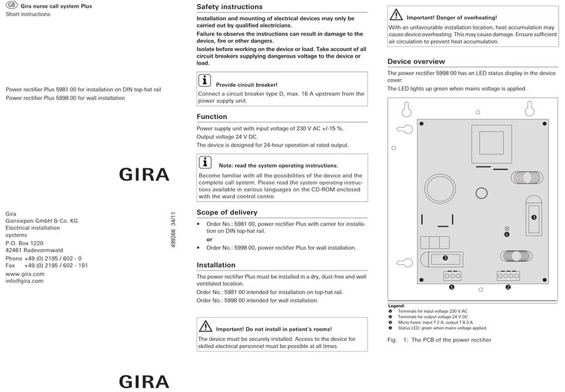
Legend:
Terminals for input voltage
230 V AC, see fig. 2
Terminals for output voltage
24 V DC, see fig. 2
Signal contacts, see fig. 2
Flat ribbon cable connection
for status LED in housing
cover
Fuse (input 230 V),
T2A
Fuse (output),
T 6.3 A



Status LED
connection


Gira
Giersiepen GmbH & Co. KG
Electrical installation
systems
P.O. Box 1220
42461 Radevormwald
Phone +49 (0) 2195 / 602 - 0
Fax +49 (0) 2195 / 602 - 191
www.gira.com
[email protected]
499268 34/11
Netzteil_mit_USV_EN.fm Seite 1 Sonntag, 28. August 2011 7:27 19
Fig. 2: PCB connections
Start-up
Carry out the following steps:
1. Connect 230 V AC input voltage (see fig. 2).
2. Connect system devices to the 24 V connection terminal (see
fig. 2). Note the energy points section of the system operating
instructions.
3. If required, wire the signal contacts (see fig. 2).
Batteries
Secure batteries after inserting into housing with the supplied vel-
cro strap.
Warranty
The warranty is provided in accordance with statutory require-
ments via the specialist trade.
Please submit or send faulty devices postage paid together with
an error description to your responsible salesperson (specialist
trade/installation company/electrical specialist trade).
They will forward the devices to the Gira Service Center.
Technical data
Output voltage in battery operation
Important! Danger!
Electric shock if live parts are touched.
Electric shock may lead to death.
Isolate all appropriate circuit breakers and fuses before working on
the device or load. Cover up live parts in the vicinity!
LN
d
F1 F2
+24V +24V BAT+ BAT-GNDGND
230 V~ 24VDC
Signal contacts
Mains voltage okay
Mains voltage not okay
Charging device okay
Charging device not okay
Battery okay
Battery not okay
Important!
Avoid damage to batteries
from complete drainage.
Complete drainage causes permanent impact on performance.
Shutdown threshold 21.4 V.
Input (primary voltage)
Rated voltage: 115 V (-15 %) to
230 V (+15 %)
Mains frequency: 45 to 65 Hz
Output (secondary voltage)
Output voltage in mains operation: 27.2 V (+/- 0.5 %)
Output voltage in battery operation: 24 V (+/- 0.5 %)
Rated output current: 6 A
Charging current limitation: yes
Output power: 150 W
Battery capacity: 2 x 12 Ah
Battery voltage thresholds
Switching threshold for advance
warning prior to battery shut-down:
1.85 V / cell
Switching threshold for complete
drainage protection:
1.8 V / cell
Protection class: I
Protection level: IP 30
Fuse on the primary side: T 2.0 A
Fuse on the secondary side: T 6.3 A
Ambient temperature at 100% load: -5 ºC to +40 ºC
Dimensions (L x W x D): approx. 320 x 240 x 120 mm
Weight: approx. 10 kg,
incl. batteries
Netzteil_mit_USV_EN.fm Seite 2 Sonntag, 28. August 2011 7:27 19

Other manuals for 834 Plus

1

This manual suits for next models

1

Other Gira Medical Equipment manuals

Gira Plus 5981 00 Manual

Gira

Gira Plus 5981 00 Manual

Gira 834 Plus User guide

Gira

Gira 834 Plus User guide

Popular Medical Equipment manuals by other brands

DeRoyal LMB Instructions for use

DeRoyal

DeRoyal LMB Instructions for use

endolite Navigator Foot manual

endolite

endolite Navigator Foot manual

Haag-Streit OCTOPUS 900 Instructions for use

Haag-Streit

Haag-Streit OCTOPUS 900 Instructions for use

Alaxo AlaxoStent C Instructions for use

Alaxo

Alaxo AlaxoStent C Instructions for use

HemoCue Hb 301 operating manual

HemoCue

HemoCue Hb 301 operating manual

Tollos Cirrus Service manual

Tollos

Tollos Cirrus Service manual

KaVo LIFEtime 2210 operating instructions

KaVo

KaVo LIFEtime 2210 operating instructions

Fresenius Medical Care DIASAFE 2008 K troubleshooting guide

Fresenius Medical Care

Fresenius Medical Care DIASAFE 2008 K troubleshooting guide

HABYS evero V4 user manual

HABYS

HABYS evero V4 user manual

ECOPOSTURAL C7934 instructions

ECOPOSTURAL

ECOPOSTURAL C7934 instructions

Westmed Vibralung Acoustical Percussor Instructions for use

Westmed

Westmed Vibralung Acoustical Percussor Instructions for use

Otto Bock 17KO1 Series Instructions for use

Otto Bock

Otto Bock 17KO1 Series Instructions for use

COLPHARMA Ai 100 FAMILY manual

COLPHARMA

COLPHARMA Ai 100 FAMILY manual

NoxBox NOxBOXi operating instructions

NoxBox

NoxBox NOxBOXi operating instructions

DC Med IFU-1701 Instructions for use

DC Med

DC Med IFU-1701 Instructions for use

SpanLink RAD manual

SpanLink

SpanLink RAD manual

Rigel 288 PLUS Faq

Rigel

Rigel 288 PLUS Faq

Mercoframes Optical Corp Volk iNview quick start guide

Mercoframes Optical Corp

Mercoframes Optical Corp Volk iNview quick start guide

manuals.online logo
manuals.online logoBrands
  • About & Mission
  • Contact us
  • Privacy Policy
  • Terms and Conditions

Copyright 2025 Manuals.Online. All Rights Reserved.