Gira 834 Plus User guide
Gira radio emergency set
5914 ..
Gira radio emergency set
Installation, start-up, operation


3
06.2017/V 1.2
1. Introduction ........................................................................................... 4
1.1 General notes ................................................................................................. 4
1.2 Scope of delivery ............................................................................................ 5
1.3 Area of application ......................................................................................... 8
1.4 Functional description .................................................................................... 8
1.5 Interfaces and connection options ................................................................. 9
2. Installation and start-up ......................................................................... 11
2.1 Radio signals of the devices ........................................................................... 11
2.2 Recommended installation heights for the devices ....................................... 11
2.3 Recommended installation height for the radio call module.......................... 11
2.4 Installation of the power supply unit for the radio call module ...................... 12
2.5 Starting up the radio emergency set .............................................................. 13
2.5.1 Removing the battery discharge protection ................................................... 13
2.6 Adding new devices to a radio emergency set /
deleting device assignments from a radio emergency set............................. 14
2.6.1 Expanding an existing radio emergency set with one or several devices ...... 14
2.6.2 Deleting device assignment to a radio emergency set .................................. 15
2.6.3 Testing the connection quality of the installation........................................... 16
2.7 Relay in the radio call module ........................................................................ 17
2.8 Starting up the radio emergency set .............................................................. 17
2.8.1 Example for a standard installation ................................................................ 18
2.9 DIP switch on the circuit board of the call module ........................................ 19
2.10 Error signalling ............................................................................................... 20
2.10.1 Weak battery .................................................................................................. 20
2.10.2 Loss of radio connection ................................................................................ 20
2.10.3 Multiple loss of radio connection (> 20 times in 24 h) ................................... 21
2.10.4 Device reset to factory setting........................................................................ 22
2.10.5 Device defect.................................................................................................. 22
3. Operation ............................................................................................... 23
3.1 Call triggering ................................................................................................. 23
3.2 Call signalling ................................................................................................. 23
3.3 Switching call off............................................................................................ 23
3.4 Status display and display of faults in the call module................................... 24
3.5 Setting of acoustic signalling in the call module ............................................ 24
3.6 Power failure .................................................................................................. 24
3.7 Maintenance and care.................................................................................... 24
4. Technical data ........................................................................................ 25
4.1 Current consumption of components ............................................................ 26
5. Warranty ................................................................................................ 26
Introduction
406.2017/V 1.2
1. Introduction
The Gira radio emergency set is a radio-based, expandable call system (transmission
frequency 868.35 MHz) and is suitable for many applications, for example for installation
in WC's suitable for the handicapped.
1.1 General notes
The technical data and specifications contained in this documentation may be changed
without prior notification. The illustrations are also non-binding.
Subject to technical modifications.
No part of these documents may be duplicated or transmitted for any purpose, regardless
of the manner and means used (electronic or mechanical), without the expressed written
consent of Gira, Giersiepen GmbH & Co. KG.
All rights reserved!
© by Gira, Giersiepen GmbH & Co. KG
Dahlienstraße
42477 Radevormwald, Germany
i
Note: Up-to-date information is available on the Gira website.
As the device you have purchased is constantly being further developed and updated,
information in this manual may no longer be up-to-date.
Current product information is always available on the Gira website:
http://www.gira.de
Current documentation for your product is available at
http://www.download.gira.de
Introduction
5
06.2017/V 1.2
1.2 Scope of delivery
The following components are contained in the scope of delivery of the radio emergency set
(Order No. 5914 ..):
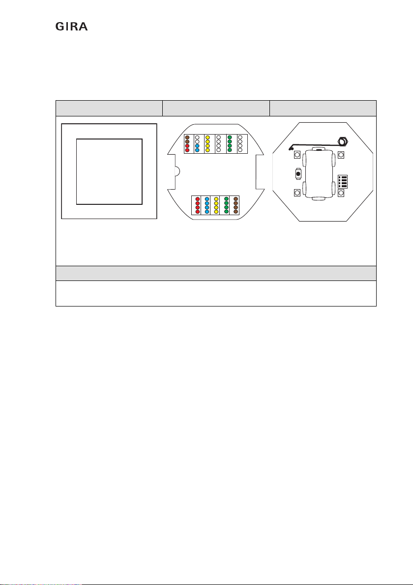
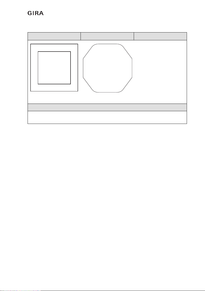
Radio call module, individual part order number 5935 00
Device view Rear connections Front of device
Contains both the control
electronics for the radio
emergency set as well as
the signal light and buzzer.
(1) Power supply
(2) Relay connection
(3) RS 834+ connection
(1) Programming button
(2) Antenna
(3) LED display
(4) Battery
(5) DIP switch
Function: Call display / status display
The radio call module is the central unit for the radio communication of the set, and
contains the signal light and buzzer for the display of calls, and a relay contact.
+12V
GND
485+
485 -
REL
REL
+12V
GND
Z-BUS
MIC
LS
(1)
(2)
(3)
_+
(1)
(2)
(3)
(3)
(3) (3)
(4)
(5)
Introduction
606.2017/V 1.2
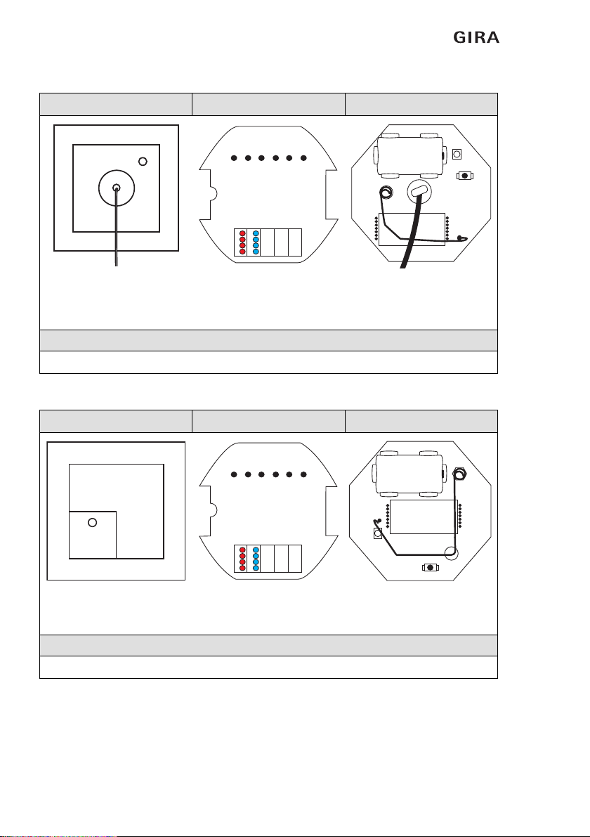
Radio pull-cord button, individual part order number 5932 ..
Radio switch-off button, individual part order number 5931 ..
Device view Rear connections Front of device
Connection via radio to:
Radio call module (1) 12 V DC power supply
(optional) (1) Programming button
(2) Antenna
(3) LED display
(4) Battery
(5) Pull-cord button
Function: Call triggering
Triggers calls by pulling the cord. Reassurance light in the housing. Battery-operated.
Device view Rear connections Front of device
Connection via radio to:
Radio call module (1) 12 V DC power supply
(optional)
(1) Programming button
(2) Antenna
(3) LED display
(4) Battery
Function: Call switch-off
For switching off calls. Battery-operated.
+12V
GND
(1)
_+
(1)
(2)
(3)
(4)
(5)
+12V
GND
(1)
_+
(1)
(2)
(3)
(4)
Introduction
7
06.2017/V 1.2
Power supply unit 12 V / 1 A, individual part order number 5930 ..
Device view
Power supply unit for flush-
mounted installation
Function: Power supply of the radio call module
230 V / 12 V, 1 A. Power supply of the call module. Can also be used for supply of the pull-
cord button and switch-off button.
230 V~ AC
12 V- DC

Introduction
806.2017/V 1.2
1.3 Area of application
The Gira radio emergency set is used to signal emergency situations and for alarming
personnel. Signalling of an emergency situation is via a red signal light in the radio call
module as well as acoustically via an optionally activated buzzer, also in the radio call module
(factory setting: off).
The Gira radio emergency set is suited to all areas of application in which the installation of
a call system according to DIN VDE 0834 is not expressly required, but where use of a call
system is still expedient and is also thoroughly recommended due to high risk factors. Thus
installation is possible in locations such as public outdoor facilities (e.g. toilet rooms in public
baths), in public buildings such as administrative authorities, museums, department stores
and also at places of work with especially high risk potential.
The range of application therefore covers for example all rooms in which persons who are
alone (without visual or acoustic contact to their surroundings) may become subject to an
emergency situation.
Gira assumes neither legal responsibility nor provides a guarantee for errors and damage of
any kind as a result of improper use and/or unprofessional installation of the emergency set.
1.4 Functional description
A call is triggered if a person in need of help pulls the cord of the radio pull-cord button. The
triggered call is signalled by a reassurance light in the housing of the radio pull-cord button.
The red signal light of the radio call module simultaneously signals outside the room that
help is required.
The radio switch-off button is located in the room where the call was triggered and is
installed adjacent to the door. A triggered call can be deactivated by the person hurrying
to give help pressing the green switch-off button.
Visual call signalling is with a red continuous light.
Acoustic call signalling in the radio call module can be switched on or off via the DIP switch
on the circuit board (see Figure 2.3:) (factory setting: buzzer off).
The radio call module features a zero-voltage relay contact (see 2.7). The relay functions as
a zero-voltage NC contact. This can be used for example for connection of a Gira TeleCoppler
(optional).
After power failure, the function of the emergency set is maintained as all devices in the radio
emergency set are battery-buffered (please see the technical data for precise designations
of the battery types used).
The radio emergency set can be expanded by purchasing further components:
• Radio pull-cord button (Order No.: 5932 ..
• Radio switch-off button (Order No.: 5931 ..)
Introduction
9
06.2017/V 1.2
A maximum of 8 pull-cord buttons or switch-off buttons can be connected to a call module.
The maximum distance between the devices of an emergency set can be up to 100 m in the
free field.
1.5 Interfaces and connection options
The radio emergency set features the following interface:
– The radio call module has a zero-potential relay contact (NC).
A Gira TeleCoppler (Order No.: 2335 00) can be connected to this.
i
Note: Negative influence of radio signals.
With installation, disruptive factors that negatively influence the radio signals should
be taken into account (see 2.1).

Introduction
10 06.2017/V 1.2
Installation and start-up
11
06.2017/V 1.2
2. Installation and start-up
Installation of the Gira radio emergency set must be carried out by a skilled electrician.
He must observe the applicable requirements of DIN VDE 0834, DIN VDE 0100 and further
standards as well as statutory standards.
The devices of a radio emergency set are pre-configured for immediate use and are installed
in flush-mounted boxes.
2.1 Radio signals of the devices
Upon device installation several important rules must be observed to achieve the best
possible radio transmission:
- The alignment or length of antennas must not be modified.
- The distance between the radio call module and the other devices of an emergency set
should be at least 1 m (except the power supply unit).
- If possible, maintain a distance to large metallic surfaces (e.g. metal doors) and large
electrical devices (motors, electrical switching cabinets etc.).
- Also maintain a distance to other functional assemblies that also use radio
components.
- Do not install near to the ground (at least 0.5 m above the ground).
Basic rule: the higher a radio component is installed, the longer its range.
- Attenuation of radio signals is achieved by reinforced concrete, metal grids, thick walls
etc.
- Damp in materials or in the room reduces the penetration of radio waves.
2.2 Recommended installation heights for the devices
DIN 18024-2 ("Barrier-Free Construction") specifies that operating elements are
mounted so they can also be easily reached by wheelchair users. A mounting
height of 0.85 m is specified.
With pull-cord buttons in bathroom units, specific requirements in DIN 0100-710
must be adhered to. Pull-cord buttons must be fitted at least 20 cm above the
highest possible position of the shower head.
It must be possible for the cord of the pull cord button to be reached by persons lying
on the floor.
2.3 Recommended installation height for the radio call module
The radio call module is for signalling an emergency situation and should be installed at
a height of 1.5 m to 2.2 m.
i
Note: Reef knot on the handle of the pull-cord button.
The handle of the pull cord button must be attached to the pull-cord by a reef knot to ensure
that the cord cannot be pulled out of the handle.

Installation and start-up
12 06.2017/V 1.2
2.4 Installation of the power supply unit for the radio call module
Care must be taken that the 230 V AC cable remains separate from the 12 V DC cable
during installation.
Figure 2.1: Separation of the power supply areas with the power supply unit
i
Notes
Connection of the power supply unit must be carried out by a skilled electrician only.
Ensure correct polarity when connecting the device. Before start-up, check the mains
voltage. Heating up of the housing during operation is normal and safe.
Recommendation: Position the power supply unit to partition the cables.
Recommendation: Install the power supply unit and radio call module in deep installation
boxes.
Important! Ensure uninterruptible power supply!
The radio call module has a 3 V lithium battery that with power failure ensures device
functionality for up to 6 hours.
The device indicates power failure by rapid flashing.
Despite this we recommend an uninterruptible power supply for operation of the call
module, so that if power failure occurs the function of the radio emergency set is still
permanently maintained.
230 V~
12 V-
Flush-mounted
1 A
power
supply unit

Installation and start-up
13
06.2017/V 1.2
2.5 Starting up the radio emergency set
The components of a Gira radio emergency set are factory pre-configured. This means
that the radio connection (transmission frequency 868.35 MHz) between the devices
is automatically established during installation. The devices of the set do not have to be
configured or taught in.
2.5.1 Removing the battery discharge protection
Batteries are placed in the intended battery holder in the factory.
To avoid discharge during storage/delivery, a strip separates the battery pole and
contact in the battery holder.
This strip must be removed with each device during installation/start-up.
i
Observe installation distances of the radio components
Installation distances that are too small or too large may negatively influence a stable radio
connection.
Recommended distances: minimum 1 m, maximum 100 m (in the free field).

Installation and start-up
14 06.2017/V 1.2
2.6 Adding new devices to a radio emergency set /
deleting device assignments from a radio emergency set
2.6.1 Expanding an existing radio emergency set with one or several devices
i
Note:
The description applies for devices not yet taught in with a set!
The following description applies for single devices to be integrated into an existing set.
Devices that are part of a set (Order No.: 5914 ..) are factory pre-configured and
interconnected.
To delete the device assignment to a radio emergency set, see 2.6.2.
Important:
Only add several devices one after another.
For each device, implement steps 2 to 3 in succession.
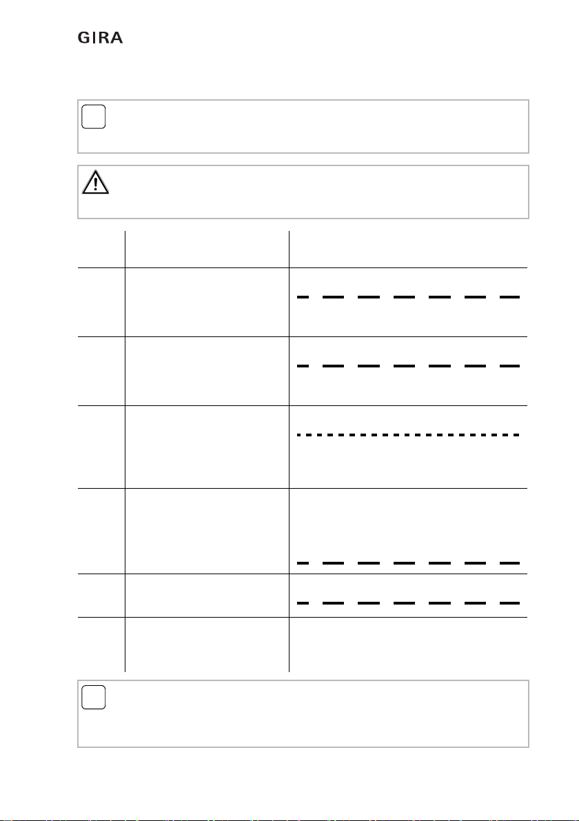
Step Set the device into
programming mode
Response (signalling)
of the device during teach-in
1 1. Device = radio call module:
Press and hold the program-
ming button for longer than
3seconds.
2 2. Device = new device
Press and hold the program-
ming button for longer than
3seconds.
3Result:
Radio contact is established,
the status LED on both
devices lights continuously
for 5 seconds.
The taught-in device exits
programming mode.
The radio call module remains
in programming mode.
4 Teaching in a further device
Continue with step 2.
5 Exit programming mode
Press the programming button
once.
Flashing frequency: 1
Flashing frequency: 1 Hz
Continuous light: 5 seconds
The LED goes out
Flashing frequency: 1 Hz
Flashing frequency: 1 Hz
The LED goes out
Installation and start-up
15
06.2017/V 1.2
2.6.2 Deleting device assignment to a radio emergency set
i
Note:
Description applies to devices that are part of a radio emergency set!
To assign devices to a radio emergency set, see 2.6.1.
Important:
Only delete several device assignments one after another.
For each device, implement steps 2 to 3 in succession.
Step Set the device into
programming mode
Response (signalling)
of the device during deletion of assignment
1 1. Device = radio call module:
Press and hold the program-
ming button for longer than
3seconds.
2 2. device to be deleted
Press and hold the program-
ming button for longer than
3seconds.
3Result:
The device assignment to the
set is deleted and the status
LEDs on both devices flash
rapidly.
The device deleted from the
assignment exits programming
mode.
The radio call module remains
in programming mode.
4 Deleting a further device
Continue with step 2.
5 Exit programming mode
Press the programming button
once.
i
Note:
Programming mode is terminated automatically after 5 minutes.
Programming mode and thus also the flashing of the LED terminates automatically after
5 minutes independently of the programming button being pressed.
Flashing frequency: 1 Hz
Flashing frequency: 1 Hz
Flashing frequency: 2 Hz
The LED goes out
Flashing frequency: 1 Hz
Flashing frequency: 1 Hz
The LED goes out
Installation and start-up
16 06.2017/V 1.2
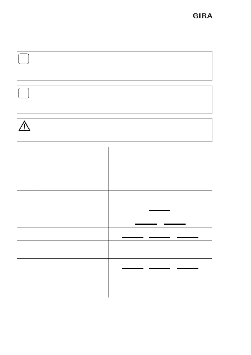
2.6.3 Testing the connection quality of the installation
As outlined in chapter 2.1, radio connection quality depends on various factors.
i
Note:
Test the connection quality before installation.
It is advisable to test connection quality prior to installing the devices so that another
installation location can be selected if necessary.
i
Note:
The description applies both to pre-configured devices that are part of a radio
emergency set and to devices added to a set!
To assign devices to a radio emergency set, see 2.6.1.
Important:
Only test the connection quality of several devices one after another.
For each device, implement steps 1 and 2 in succession.
Step Set the device into test mode Visual and acoustic display of the
connection quality in the call module
11.Device: If the buzzer is activated, an acoustic signal is
output.
Press the programming button
for less than 3 seconds.
The devices exchange information.
This process takes several seconds.
2 Display in the call module: repeated 3 times within 5 seconds
a) Connection very good
b) Connection good
c) Critical connection
3 Testing a further device
Begin again with step 1.
4 Result: Critical connection
Find another installation location
for the device and observe the
points specified in chapter 2.1.
Then test again.
Flashes 1 x
Flashes 2 x
Flashes 3 x
Flashes 3 x
Installation and start-up
17
06.2017/V 1.2
2.7 Relay in the radio call module
The relay functions as a zero-voltage NC contact.
The contact is open when:
• no voltage is applied
• a call is active
• a fault exists.
The contact is closed when:
• the device is ready for operation and there is no call and no fault.
The relay can be switched in series with other openers to signal faults or alarms.
2.8 Starting up the radio emergency set
Test all functions of the radio components:
• Measure the 12 V DC supply voltage of the power supply unit.
The power supply must not drop below 11.8 V DC.
• Pull the cord of the radio pull-cord button.
The red light in the housing of the radio pull-cord button lights up (reassurance light).
The red signal light in the radio call module lights up.
• Press the radio switch-off button, the red reassurance light in the housing of the radio
pull-cord button and the red signal light in the radio call module go out.
i
Prerequisite:
Devices are assigned and part of a radio emergency set!
To assign devices to a radio emergency set, see 2.6.1.
Devices that are part of a set (Order No.: 5914 ..) are factory pre-configured and
interconnected.
Installation and start-up
18 06.2017/V 1.2
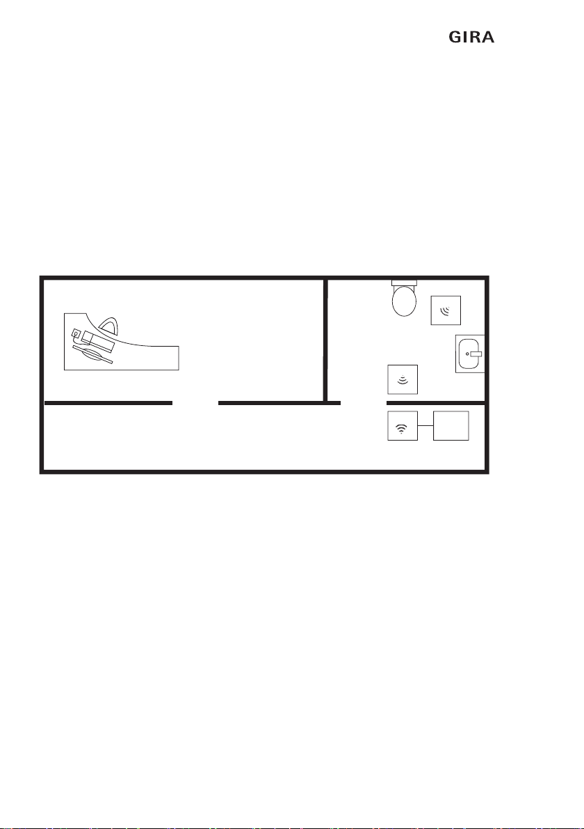
2.8.1 Example for a standard installation
A WC suitable for the handicapped with pull-cord button and switch-off button can be
equipped with the Gira radio emergency set. A call triggered by the pull-cord button is
signalled by the red signal light of the call module outside, adjacent to the door of the WC.
The call is switched off with the switch-off button in the WC area next to the door when the
danger situation has been dealt with.
Components used:
– Radio call module (RMF)
– Radio pull-cord button (ZTF)
– Radio switch-off button (ATF)
– Flush-mounted power supply unit 12 V DC, 1 A for the call module (NG12V)
Figure 2.2: Example for use of the radio emergency set in a WC suitable for the handicapped
ZTF
ATF
RMF NG12V
Installation and start-up
19
06.2017/V 1.2
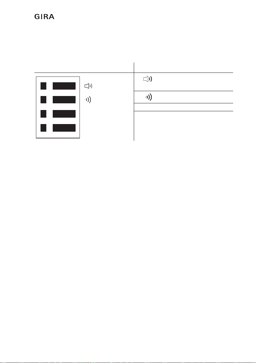
2.9 DIP switch on the circuit board of the call module
The factory setting is:
All 4 switches are in the left position, all options are "OFF".
Figure 2.3: DIP switch in the call module
DIP switch in the call module Symbol meanings
Buzzer off/buzzer on
Factory setting: off
For future application
834+ For future application
Term For future application
834+
Term
Installation and start-up
20 06.2017/V 1.2
2.10 Error signalling
2.10.1 Weak battery
2.10.2 Loss of radio connection
Device display
with weak battery
Call module display
Possible cause:
weak battery.
Eliminate the cause:
New battery, see 3.7.
Result:
Device display Call module display
Possible cause (see 2.1):
• e.g. unsuitable installation location
• e.g. unsuitable climatic conditions
(humidity)
• e.g. unsuitable distance between the
call module and the other devices
Eliminating the cause:
• e.g. select a suitable installation location
• e.g. create suitable climatic conditions
(low humidity)
• e.g. ensure more suitable distance
between the call module and other
devices
Result:
Flashes
1 x short
Flashes
1 x short
Pause
5 sec.
Flashing frequency:
2 Hz
The LED goes out
The LED goes out
Flashes
1 x short
Flashes
1 x short
Pause
5 sec.
Flashing frequency: 1 Hz
The LED goes out
The LED goes out
Other manuals for 834 Plus
1
Table of contents
Other Gira Medical Equipment manuals


Popular Medical Equipment manuals by other brands


Getinge
Getinge Arjohuntleigh Nimbus 3 Professional Instructions for use

Mettler Electronics
Mettler Electronics Sonicator 730 Maintenance manual

Pressalit Care
Pressalit Care R1100 Mounting instruction

Denas MS
Denas MS DENAS-T operating manual

bort medical
bort medical ActiveColor quick guide

AccuVein
AccuVein AV400 user manual


