Bettersafe Guard Angel User manual

Installation Manual
October 2015: Rev 1.0
Technical
Manual
October 2015
Revision 1.0

Installation Manual
October 2015: Rev 1.0
2
General Information
Guard Angel is tested in accordance with BS EN 13374 and BS EN 14122-3.
It is designed for use on roofing areas and raised platforms for access to areas of buildings and
structures that are deemed unsafe to do so otherwise.
The Guard Angel System is not designed for use as an attachment point for fall protection PPE.
The equipment used should be stored in a safe manner and moved to the point of installation in
line with the Manual Handling Regulations in the region of use.
Installation should only be carried out by a trained and competent installer with the permission of
Fall Angel or their appointed representatives. Appropriate safety measures must be taken to
ensure the complete safety of all installation personnel.
All tools used must be in good working order and calibrated and tested where applicable.

CONFIGURATION
Edge Protection - System Configuration
TYPICAL LAYOUT
INSITU DIMENSIONS

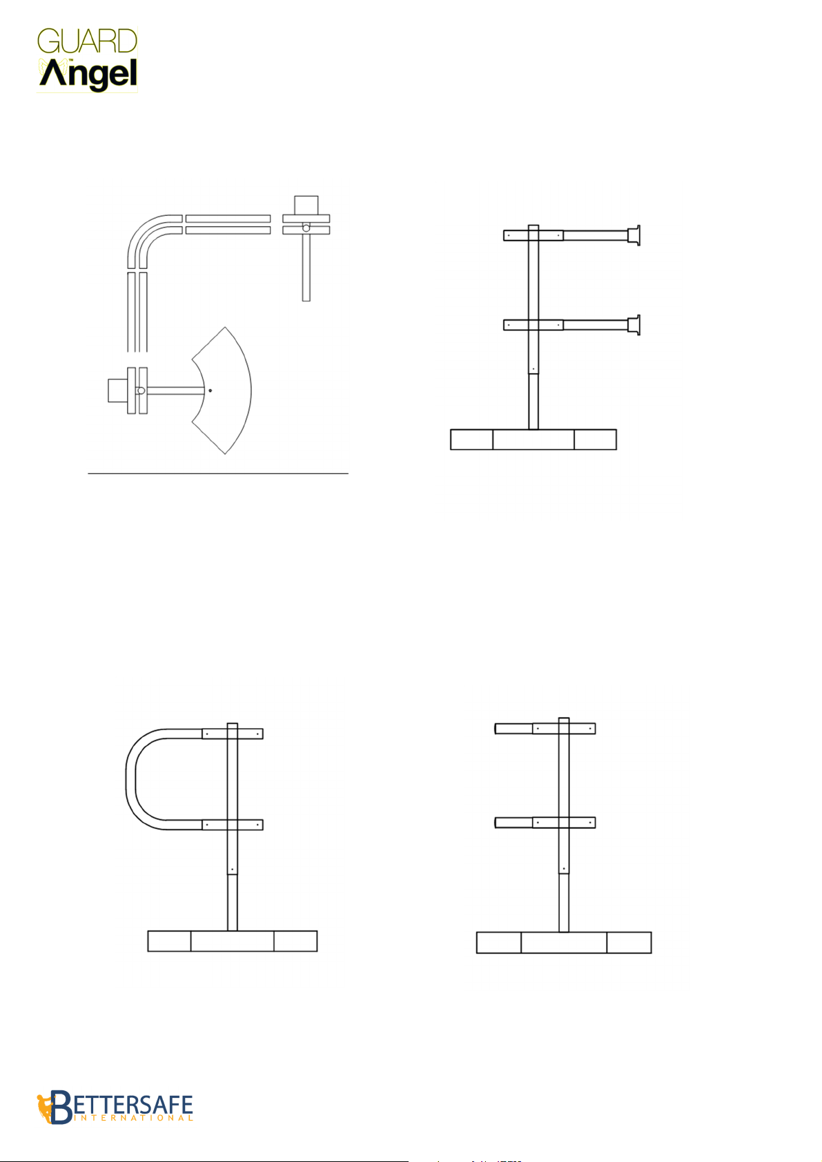
TYPICAL CORNER DETAIL TYPICAL WALL TERMINATION DETAIL
TYPICAL ‘D’ END TERMINATION DETAIL TYPICAL END CAP TERMINATION DETAIL
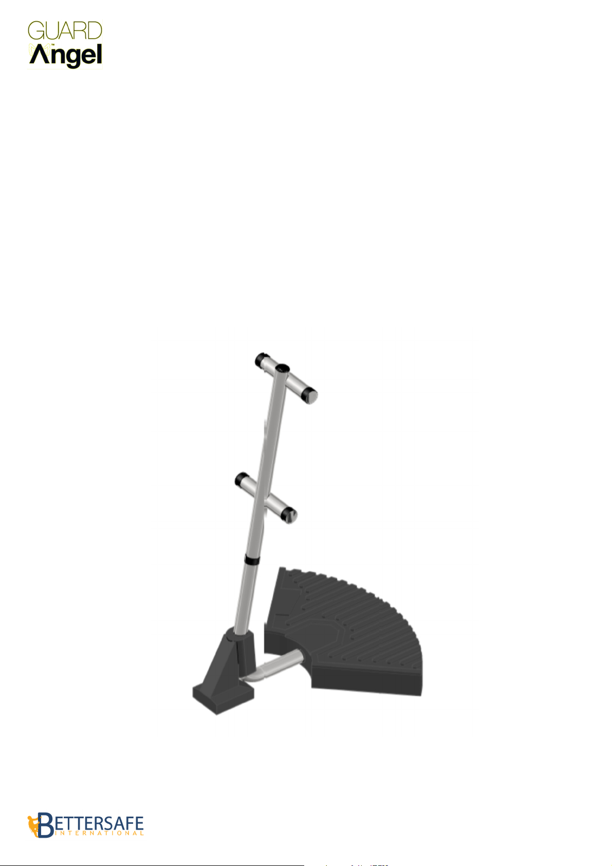
CONFIGURATION
Edge Protection - System Configuration
Free Standing System Shown for Example Only

Installation Manual
October 2015: Rev 1.0
System Components
& Specifications

SPECIFICATION
Edge Protection System - Specification
MATERIAL
The main and intermediate uprights are fabricated from 2 x 54 mm pre galvanised steel to BS EN ISO 1461,
with the upper and lower cross rails manufactured from 2 x 54mm external diameter pre galvanised steel. The
lower leg sections are manufactured from 3x47.6mm hot dipped galvanised steel. Also available polyester
powder coated.
The rubber counterweight is manufactured from 100% recycled rubber compound with the fixing screws
manufactured from zinc-coated steel.
SAFETY STANDARDS
Our Freestanding guardrail is tested to the following safety standards:
•HSG-33 Health and safety in roof work.
•HSE INDG 284 “Working on roofs”.
•EN ISO 14122 Part 3.
•EN 13374 Class A.
•BS 6399: Part 2 1995 Wind Code.

THE MAIN UPRIGHT
The main upright sits on the roof and has a counterbalance weight attached, and the adjustable top riser unit.
The foot of the upright which rests on the roof is a moulded rubber boot to prevent piercing to the roof waterproofing layer.
By loosening the fixing screws in the body of the top riser, the unit can be raised or lowered on the main upright to adjust the
height of the top and middle rails or to raise and lower the main upright.
MATERIALS
The main upright is manufactured from 2mm x 54mm pre galvanised steel tube, also is available powder coated to any RAL
colour.
NOTE: Main upright shown here with top riser unit attached.
MAIN UPRIGHT
FREE STANDING

THE INTERMEDIATE UPRIGHT
The intermediate upright is designed to be installed un-weighted as an intermediate support. Just as with the main
upright, this component consists of two separate components but is delivered pre-assembled ready to install.
The intermediate upright also features the protective moulded rubber boot to isolate the foot from the roof membrane.
MATERIALS
The intermediate upright is manufactured from 2mm x 50mm pre galvanised steel tube, and is also available powder
coated to any RAL colour.
NOTE: Intermediate upright shown here with top riser unit attached.
INTERMEDIATE UPRIGHT
FREE STANDING

COUNTERWEIGHT
The weight is designed to be attached to each of the main uprights, and is fixed in place with a small zinc coated grub
screw which provides the necessary counterbalance weight to prevent the system from being moved.
MATERIALS
The weight is 20kg and is manufactured from 100% recycled rubber compound.
COUNTERWEIGHT
FREE STANDING

DOUBLE WEIGHT CONNECTOR
The Double Weight Connector is used on the free standing system to allow 2 weights to be attached to one leg when
used at an end of a system or a gate termination.
MATERIALS
Manufactured from 1.5mm x 47mm steel. These are also available powder coated to any RAL colour.
DOUBLE WEIGHT CONNECTOR
FREE STANDING

CROSS RAIL
All the main cross rails are supplied pre-cut to 2.50m lengths for ease of installation.
MATERIALS
The lightweight main rails are manufactured from 1.5mm light gauge, pre galvanised steel and are available powder
coated to any RAL colour.
CROSS RAIL
ALL SYSTEMS

THE SWEEPING BEND
The sweeping bend is an ergonomically designed 90˚swept bend. This flexible pre-formed component can be used for
both horizontal and vertical bends The fitting incorporates zinc coated grub screws for easy installation.
MATERIALS
The swept bend is manufactured from 2mm steel and manufactured from pre galvanised steel. These are also available
powder coated to any RAL colour.
THE SWEEPING BEND
ALL SYSTEMS

THE VARIABLE BEND
The sweeping bend is an ergonomically designed 90˚swept bend. This flexible pre-formed component can be used for
both horizontal and vertical bends The fitting incorporates zinc coated grub screws for easy installation.
MATERIALS
The swept bend is manufactured from 2mm steel and manufactured from pre galvanised steel. These are also available
powder coated to any RAL colour.
THE VARIABLE BEND
ALL SYSTEMS

RAIL JOINER
The Rail Joiner is used to re-join sections of horizontal rail should they have to be shortened for transport of mobility
on site.
MATERIALS
The swept bend is manufactured from 2mm steel and manufactured from pre galvanised steel. These are also available
powder coated to any RAL colour.
RAIL JOINER
ALL SYSTEMS

THE ‘D’ END
The pre-formed 180˚bend inserts into the top riser and is a quick and convenient way of terminating a run of guardrail.
This flexible pre-formed component can be used for both horizontal and vertical terminations.
MATERIALS
The ‘D’ end’s are manufactured from 2mm steel and is manufactured from pre galvanised steel.These are also
available powder coated to any RAL colour.
D-END
ALL SYSTEMS

THE UPPER LEG
This is designed to be installed as an intermediate or end/corner support. This component consists of two separate
components but is delivered pre-assembled ready to install.
MATERIALS
The intermediate upright is manufactured from 2mm x 50mm pre galvanised steel tube, and is also available powder
coated to any RAL colour.
UPPER LEG
FIXED SYSTEMS

LOWER LEG
This lower leg is used for all fixed base systems.
MATERIALS
Manufactured from hot dip galvanised steel.
LOWER LEG
TOP FIX SYSTEMS

THE LEG FOOT
The Leg Foot is a hot dip galvanised foot for the upright leg section. This is fixed to the based plate used for the
profiled sheeting fix and the standing seam fix systems.
MATERIALS
The swept bend is manufactured from mild steel and hot dip galvanised steel. These are also available powder coated
to any RAL colour.
LEG FOOT
TOP FIX SYSTEMS

THE BASE PLATE
The base plate is used for fixing to profiled and standing seam roofing systems. It should be used in conjunction with
the fixed foot and either the tek screws or clamps as required.
MATERIALS
The swept bend is manufactured from aluminium.
BASE PLATE
TOP FIX SYSTEMS

FIXINGS
ROOFING FIX SYSTEMS
Rivets
Other manuals for Guard Angel
1
Table of contents
Other Bettersafe Protection Device manuals