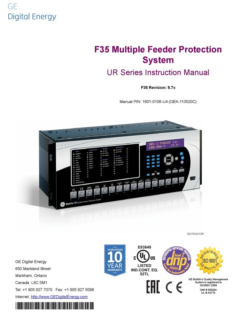
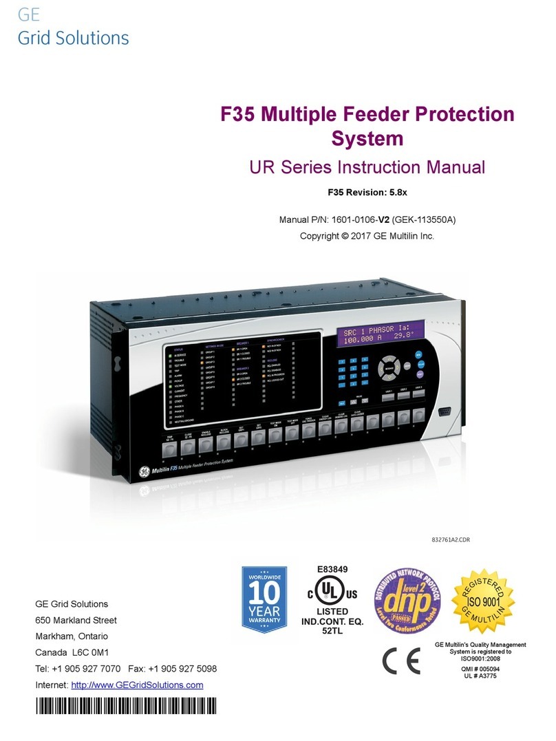
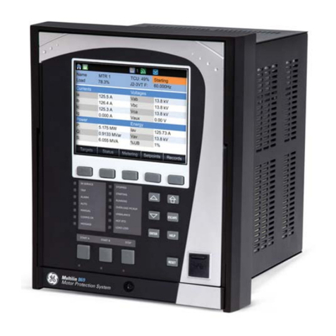
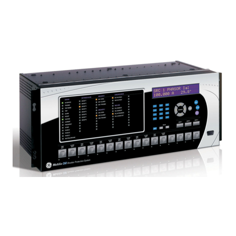
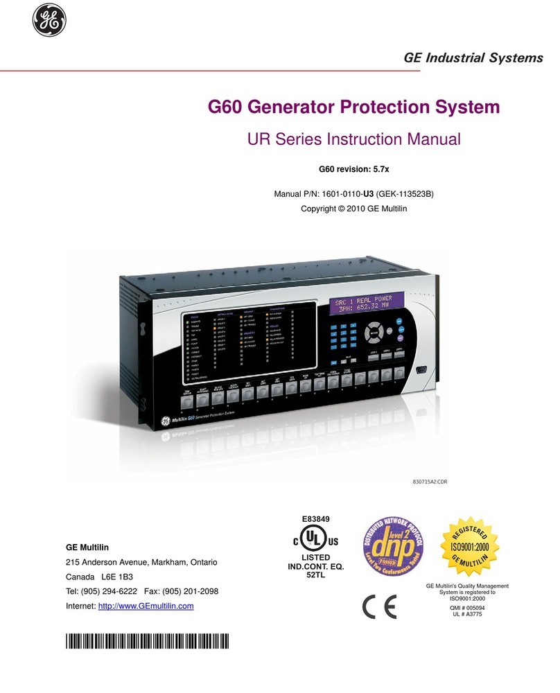
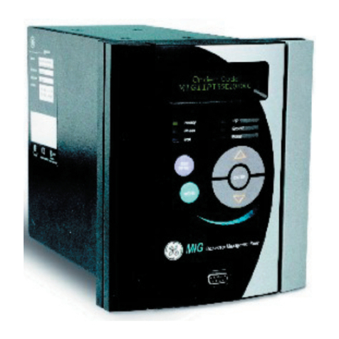
GE Multilin 3 Series User manual

MultilinTM 3 Series Retrofits
from M & MII Family, 239, 735/737, MLJ, & TOV relays
LISTED
Retrofit Guide
3 Series version: 2.3x
GE publication code: 1601-0380-A2 (GEK-130924A)
*1601-0380-A2*
GE
Grid Solutions

ii
Copyright © 2017 GE Multilin Inc. All rights reserved.
3 Series Retrofit Guide.
3 Series Retrofit is a registered trademark of GE Multilin Inc.
The contents of this manual are the property of GE Multilin Inc. This documentation is
furnished on license and may not be reproduced in whole or in part without the permission
of GE Multilin Inc. The content of this manual is for informational use only and is subject to
change without notice.
Part numbers contained in this manual are subject to change without notice, and should
therefore be verified by GE Multilin Inc. before ordering.
Part number: 1601-0380-A2 (September 2017)
For further assistance
For product support, contact the information and call center as follows:
GE Grid Solutions
650 Markland Street
Markham, Ontario
Canada L6C 0M1
Worldwide telephone: +1 905 927 7070
Europe/Middle East/Africa telephone: +34 94 485 88 54
North America toll-free: 1 800 547 8629
Fax: +1 905 927 5098
Website: http://www.gegridsolutions.com/multilin

iii
Safety words and definitions
The following symbols used in this document indicate the following conditions:
Note Indicates a hazardous situation which, if not avoided, will result in death or serious
injury.
Note Indicates a hazardous situation which, if not avoided, could result in death or serious
injury.
Note Indicates a hazardous situation which, if not avoided, could result in minor or
moderate injury.
Note Indicates practices not related to personal injury.
NOTE
Indicates general information and practices, including operational information and
practices, that are not related to personal injury.
General Cautions and Warnings
The following general safety precautions and warnings apply.
Note Disassembly of this unit will void the warranty. Do not attempt to open or repair the
retrofit enclosure. All repairs are to be conducted by the factory.
Note Before attempting to use the equipment, it is important that all danger and caution
indicators are reviewed.
If the equipment is used in a manner not specified by the manufacturer or functions
abnormally, proceed with caution. Otherwise, the protection provided by the
equipment may be impaired and can result in impaired operation and injury.
Note Hazardous voltages can cause shock, burns or death.
Note Installation/service personnel must be familiar with general device test practices,
electrical awareness and safety precautions must be followed.
Before performing visual inspections, tests, or periodic maintenance on this device or
associated circuits, isolate or disconnect all hazardous live circuits and sources of
electric power.
Failure to shut equipment off prior to removing the power connections could expose
you to dangerous voltages causing injury or death.
Ensure that all connections to the product are correct to avoid accidental risk of shock
and/or fire, for example from high voltage connected to low voltage terminals.
Follow the requirements of this manual, including adequate wiring size and type,
terminal torque settings, voltage, current magnitudes applied, and adequate isolation/
clearance in external wiring from high to low voltage circuits.
Use the device only for its intended purpose and application.

iv
Ensure that all ground paths are un-compromised for safety purposes during device
operation and service.
All recommended equipment should be grounded and must have a reliable and un-
compromised grounding path for safety purposes, protection against electromagnetic
interference and proper device operation.
Equipment grounds should be bonded together and connected to the facility’s main
ground system for primary power.
Keep all ground leads as short as possible.
In addition to the safety precautions mentioned all electrical connections made must
respect the applicable local jurisdiction electrical code.
It is recommended that a field external switch, circuit breaker be connected near the
equipment as a means of power disconnect. The external switch or circuit breaker is
selected in accordance with the power rating.
Ensure that the control power applied to the device, the AC current, and voltage input
match the ratings specified on the relay nameplate. Do not apply current or voltage in
excess of the specified limits.
Only qualified personnel are able to operate the device. Such personnel must be
thoroughly familiar with all safety cautions and warnings in this manual and with
applicable country, regional, utility, and plant safety regulations.
Hazardous voltages can exist in the power supply and at the device connection to
current transformers, voltage transformers, control, and test circuit terminals. Make
sure all sources of such voltages are isolated prior to attempting work on the device.
Hazardous voltages can exist when opening the secondary circuits of live current
transformers. Make sure that current transformer secondary circuits are shorted out
before making or removing any connection to the current transformer (CT) input
terminals of the device.
For tests with secondary test equipment, ensure that no other sources of voltages or
currents are connected to such equipment and that trip and close commands to the
circuit breakers or other switching apparatus are isolated, unless this is required by
the test procedure and is specified by appropriate utility/plant procedure.
When the device is used to control primary equipment, such as circuit breakers,
isolators, and other switching apparatus, all control circuits from the device to the
primary equipment must be isolated while personnel are working on or around this
primary equipment to prevent any inadvertent command from this device.
Use external disconnect equipment to isolate the mains voltage supply.
Note To ensure the settings file inside the relay is updated, wait 30 seconds after a setpoint
change before cycling power.
Note This product is rated to Class A emissions levels and is to be used in Utility, Substation
Industrial environments. Not to be used near electronic devices rated for Class B levels.

3 SERIES RETROFIT – INSTRUCTION MANUAL v
Table of Contents
1: OVERVIEW INTRODUCTION ................................................................................................................................ 1
MIF AND MIF II RELAYS .................................................................................................................. 3
MIV AND MIV II RELAYS ................................................................................................................. 5
MIG AND MIG II RELAYS ................................................................................................................ 7
MIN AND MIN II RELAYS ................................................................................................................ 11
MIW AND MIW II RELAYS .............................................................................................................. 13
239 RELAYS ........................................................................................................................................ 15
735/737 RELAYS ............................................................................................................................... 17
MLJ AND TOV RELAYS .................................................................................................................... 19
FINDING YOUR M AND MII FAMILY RELAY ORDER CODE ............................................... 21
2: CONVERTING
SETTINGS FILES
DOWNLOADING AND SAVING MIF II OR MIV II SETPOINT FILES ................................. 24
CONVERTING A SAVED MIF II OR MIV II SETPOINT FILE .................................................. 25
CONVERSION REPORT ................................................................................................................... 27
LOADING SETPOINTS FROM A FILE .......................................................................................... 28
CONVERTING MIN II 67IG1 TO 350 32N ................................................................................ 29
3: INSTALLING THE
3 SERIES RELAY
3 SERIES DIMENSIONS AND MOUNTING ............................................................................... 34
M AND MII FAMILY RELAYS .......................................................................................................... 36
239 DIMENSIONS ............................................................................................................................. 43
735/737 DIMENSIONS AND 350 RETROFIT MOUNT ......................................................... 44
MLJ AND TOV DIMENSIONS AND MOUNTING .................................................................... 46
P40 AGILE DIMENSIONS ............................................................................................................... 49
4: ELECTRICAL
INSTALLATION
350 WIRING ........................................................................................................................................ 52
345 WIRING ........................................................................................................................................ 53
339 WIRING ........................................................................................................................................ 54
MIF II WIRING ..................................................................................................................................... 56
MIV II WIRING .................................................................................................................................... 57
MIF II/MIV II TO 350 RETROFIT WIRING .................................................................................. 58
239 WIRING ........................................................................................................................................ 62
735/737 WIRING .............................................................................................................................. 65
A: APPENDIX WARRANTY ......................................................................................................................................... 67
CHANGE NOTES ................................................................................................................................ 67

3 SERIES RETROFIT – INSTRUCTION MANUAL vi

3 SERIES RETROFIT – INSTRUCTION MANUAL 1
3 Series Retrofit
Chapter 1: Overview
GE
Grid Solutions
Over vie w
1.1 Introduction
As the Multilin MII Family, Multilin 239, and Multilin 735/737 digital relays age, the Multilin
3Series (SR3) family of protection relays provide updated functional and economical
protection solutions for feeders, motors and transformers. The 3 Series family, including
the 350, 345, and 339, provide extensive diagnostic information allowing users to
troubleshoot and minimize downtime. 3 Series relays streamline work flow processes and
simplify engineering tasks such as configuration, wiring, testing, commissioning, and
maintenance.
The MultilinTM 3 Series Retrofit Instruction Manual offers a solution to upgrade previously
installed Multilin relays, providing detailed order code equivalencies, mechanical details,
and wiring diagrams. For common MII Family Digital relays a software conversion tool
provides conversion of existing settings files and Modbus Maps. This manual also provides
retrofit suggestions for Multilin M Family, MLJ, and TOV relays in less detail.

23 SERIES RETROFIT – INSTRUCTION MANUAL
INTRODUCTION CHAPTER 1: OVERVIEW
The MultilinTM 3 Series Retrofit takes place in four general steps, as follows.
1. Select a replacement relay - see the summary tables and the specific order code
comparisons for the MII Family relays shown in this chapter. If you need to determine
your MII relay order code, refer to section 1.10 Finding your M and MII Family relay
order code.
2. Convert the existing settings file if applicable; MIF II, and MIV II file conversion is
currently supported for most models - see Chapter 2: Converting Settings Files.
3. Install the new 3 Series Retrofit - see Chapter 3: Installing the 3 Series Relay.
4. Wire the new 3 Series Retrofit - see Chapter 4: Electrical Installation.
3 Series relays have an IP54 rating, superior to that of the MII Family relays which have an
IP52 rating. In addition, vibration tests for 3 Series relays have been passed for both the 4-
screw mount (as used in the MII Family retrofit) and 8-screw mount (as used for new
installations).

CHAPTER 1: OVERVIEW MIF AND MIF II RELAYS
3 SERIES RETROFIT – INSTRUCTION MANUAL 3
1.2 MIF and MIF II relays
MIF and MIF II features are available in 350 relays as described in the table below:
The following table describes MIF and MIF II options, and the equivalent 350 options and
order codes. In some cases the 350 options have changed from those available for MIF and
MIF II relays, so read the descriptions carefully.
NOTE
Note Order codes are subject to change without notice. See the GE Multilin website at: http://
www.gegridsolutions.com/multilin for up-to-date order codes.
Installed Relay Retrofit Relay
MIFII Digital Feeder Relay
MIF Digital Feeder Relay 350 Feeder Protection System
Feature MIF MIF II 3501
Protection &
Control
Thermal Overload: 49,
IOC: 50PH, 50PL, 50GH, 50GL, 50NH,
50NL
TOC: 51G, 51N, 51P
Cold Load Pickup: CLP
Breaker Failure: 50BF
Thermal Overload: 49(1)
IOC: 50P (2), 50G(2)
TOC: 51G(1), 51P(1)
Autoreclose: 79
Cold Load Pickup: CLP
Breaker Failure to Open
Thermal Overload: 49
IOC: 50P(2), 50N(2), 50_2, 50G/SG(2)
TOC: 51P, 51N, 51_2, 51G/SG
Other protection: 67G/SG, 32N, VTFF,
27_1, 27X, 59X, 67P, 67N, 46BC, 32,
27P, 59P, 59_2, 59N, 81U(2), 81O(2),
Arc Flash
Autoreclose: 79
Cold Load Pickup: CLP
Breaker Failure: 50BF
Other control: 60CTS, 86, 25
Monitoring &
Metering
Breaker Health
Event Recording
Breaker Health
Event Recording
Breaker Health
Event Recording
Oscillography 8 samples/cycle
maximum length 24 cycles 8 samples/cycle
maximum length 24 cycles up to 32 samples per cycle
(user-selectable)
maximum length 192 cycles
Communications Serial (RS232, RS485)
protocols: Modbus RTU
Serial (RS232, RS485)
protocols: Modbus RTU, IEC 60870-5-
103
USB
Serial (RS485) protocols: Modbus RTU,
DNP 3.0, IEC 60870-5-103
Ethernet protocols: Modbus TCP/IP,
DNP 3.0, IEC 60870-5-104, IEC 61850
GOOSE, IEC 61850, OPC-UA
Hardware 2 digital inputs
6 relay outputs
Configurable I/O
Configurable Logic
4 configurable LEDs
2 fixed LEDs
2 digital inputs
6 digital outputs
Configurable I/O
Configurable Logic
4 configurable LEDs
2 fixed LEDs
10 inputs
7 outputs (2 Form A, 5 Form C)
Configurable I/O
Configurable Logic
10 LEDs (non-programmable LEDs)
12 LEDs (programmable LEDs)
1. For additional features, refer to the 350 Instruction Manual.

43 SERIES RETROFIT – INSTRUCTION MANUAL
MIF AND MIF II RELAYS CHAPTER 1: OVERVIEW
Feature MIF order code options MIF II order code options 350 order code options
Application MIF-P-A11E100F00C
P: 3 Phase and Ground
N: Single Phase
MIFII-P-A11E00HI00
P: 3 Phase and Ground
N: Single Phase
All 350 relays come with 3 phase
and ground standard.
Curves MIFP-A-11E100F00C
A: ANSI Curves
I: IEC Curves
U: IAC Curves
C: EPTAR-C Curves (single phase
only)
MIFIIP-A-11E00HI00
A: ANSI Curves
I: IEC Curves
U: IAC Curves
C: EPTAR-C Curves (single phase
only)
All 350 relays come with ANSI, IEC,
and IAC curves standard.
Phase CT Range MIFPA-1-1100F00C
0: N models (single phase)
1: Phase CT = 1 A (0.1 - 2.4 A)
5: Phase CT = 5 A (0.5 - 12 A)
MIFIIPA-1-1E00HI00
0: Phase CT = 1/5 A
1: Phase CT = 1 A
5: Phase CT = 5 A
350E-P0-G0HEENNSNNN
P0: user selectable 1/5 A three-
phase current inputs (0.02 - 20 × CT)
Ground CT
Range
MIFPA1-1-E100F00C
1: Ground CT In = 1 A (0.1 - 2.4 A)
5: Ground CT In = 5 A (0.5 - 12 A)
N: Sensitive Ground (0.005 - 0.12 A)
MIFIIPA1-1-E00HI00
1: Ground CT In = 1 A (0.1 - 2.4 A)
5: Ground CT In = 5 A (0.5 - 12 A)
L: Extremely Sensitive Ground In
= 1 A (0.002 - 0.048 A)
N: Sensitive Ground (0.005 - 0.12 A)
350EP0-G0-HEENNSNNN
G0: user selectable 1/5 A Ground
current input (0.02 - 20 × CT)
S0: user selectable 1/5 A Sensitive
Ground current input (0.002 - 3 × CT)
Language All MIF relays come with English
standard.
MIFIIPA11-E-00HI00
E: English
F: French
T: Turkish
All 350 relays come with English
standard.
Options MIFPA11E-1-00F00C
0: Basic Model ()
1: Option 1 (Configurable I/O, Event
Recording, and Oscillography)
2: Option 2 (Option 1 and Cold Load
Pickup, Breaker Failure Protection,
Breaker Health, and Configurable
Logic)
MIFIIPA11E-0-0HI00
0: Basic Model ()
1: Option 1 (Event Recording,
Oscillography, Configurable I/O and
LEDs)
2: Option 2 (Option 1 and Cold Load
Pickup, Breaker Failure Protection,
Breaker Health, Configurable Logic,
and Circuit Breaker Control)
350EP0G0HEE-N-NSNNN
N: CLP, Lockout (86)
C: CLP, 50BF, Autoreclose (79)
All 350 relays come with Event
Recording, Oscillography,
Configurable I/O and LEDs,
Configurable Logic (up to 16),
Breaker Health, and Circuit Breaker
Control standard.1
Recloser n/a MIFIIPA11E0-0-HI00
0: without Recloser
R: with Recloser
350EP0G0HEE-N-NSNNN
N: CLP, Lockout (86)
C: CLP, 50BF, Autoreclose (79)
Power Supply MIFPA11E100-F-00C
H:
110 - 250 VDC (Range: 88~300 VDC)
110 - 230 VAC (Range: 88~264 VAC)
F: 24 - 48 VDC (Range: 19~58 VDC)
MIFIIPA11E00-HI-00
HI:
110 - 250 VDC (Range: 88~300 VDC)
110 - 230 VAC (Range: 88~264 VAC)
LO: 28 - 48 VDC (Range: 19~58 VDC)
350EP0G0-H-EENNSNNN
H: 110 - 250 VDC
110 - 230 VAC
L: 28 - 48 VDC
Protocol All MIF relays come with Modbus
RTU standard.
MIFIIPA11E00HI-0-0
0: Standard model (Modbus RTU)
C: IEC60870-5-103 with 2 Comms
ports
350EP0G0HEENN-SN-NN
SN: Standard: Front USB, Rear
RS485: Modbus RTU, DNP3.0,
IEC60870-5-1032
Environmental
Option
n/a MIFIIPA11E00HI0-0
0: None
H: Conformal Coating
350EP0G0HEENNSNN-N
N: None
H: Harsh Environment Conformal
Coating
1. Some features are implemented or configured somewhat differently in the 350 relay. See the 350 Instruction Manual for details.
2. For details of 350 communications implementation, see the 3 Series Communications Guide.

CHAPTER 1: OVERVIEW MIV AND MIV II RELAYS
3 SERIES RETROFIT – INSTRUCTION MANUAL 5
1.3 MIV and MIV II relays
MIV and MIV II features are available in 350 relays as described in the table below:
Installed Relay Retrofit Relay
MIV II Voltage/Frequency Relay
MIV Voltage/Frequency Relay 350 Feeder Protection System
Feature MIV MIV II 3501
Protection &
Control
UV: 27(2)
OV: 59(2), 59N(2)
Underfrequency: 81U(2)
Overfrequency: 81O(2)
Phase reversal: 47(1)
UV: 27P(4)
OV: 59P(4), 59N(4)
Underfrequency: 81U(4)
Overfrequency: 81O(4)
Phase reversal: 47(1)
Note: the number of elements
differs for different MIV II options.
Maximum numbers are shown.
UV: 27P(4), 27X(1), 27P_1(1)
OV: 59P(4), 59N(4), 59X(1), 59_2(2)
Underfrequency: 81U(4)
Overfrequency: 81O(4)
Other Protection: 25(1), VTFF(1),
24(1) Volt/Hz
Oscillography 8 samples/cycle
maximum length 24 cycles
MIV 1000 & 3000:
8 samples/cycle
maximum length 24 cycles
MIV 2000:
2 samples per cycle
maximum length 432 cycles
up to 32 samples per cycle
(user-selectable)
maximum length 192 cycles
Communication
s
Serial (RS232, RS485)
protocols: Modbus RTU
Serial (RS232, RS485)
protocols: Modbus RTU
USB
Serial (RS485) protocols: Modbus RTU,
DNP 3.0, IEC 60870-5-103
Ethernet protocols: Modbus TCP/IP,
DNP 3.0, IEC 60870-5-104, IEC 61850
GOOSE, IEC 61850, OPC-UA
Hardware 2 digital outputs
6 relay outputs
Configurable I/O
Configurable Logic
2 fixed LEDs
4 configurable LEDs
2 digital inputs
6 digital outputs
Configurable I/O
Configurable Logic
2 fixed LEDs
4 configurable LEDs
10 inputs
7 outputs (2 Form A, 5 Form C)
Configurable I/O
Configurable Logic
10 LEDs (non-programmable LEDs)
12 LEDs (programmable LEDs)
1. For additional features, refer to the 350 Instruction Manual.

63 SERIES RETROFIT – INSTRUCTION MANUAL
MIV AND MIV II RELAYS CHAPTER 1: OVERVIEW
The following table describes MIV II options, and the equivalent 350 options and order
codes. In some cases the 350 options have changed from those available for MIV II relays,
so read the descriptions carefully.
NOTE
Note Order codes are subject to change without notice. See the GE Multilin website at: http://
www.gegridsolutions.com/multilin for up-to-date order codes.
Feature MIV order code options MIV II order code options 350 order code options
Function MIV-1-000E000F00C
1: Voltage Functions
2: Frequency Functions
3: Voltage and Frequency Function
MIVII-1-010E00HI00
1: Voltage Functions
2: Frequency Functions
3: Voltage and Frequency Function
350E-PXGX-HE-N-N-V-SNNN
V: Voltage Metering - 27P(4), 27X(1),
27P_1(1), 59P(4), 59N(4), 59X(1),
59_2(2), 81O(4), 81U(4), 25(1), VTFF(1)
Voltage Range MIV10-0-0E000F00C
0: 10 - 250 V Setting Range
1: 2 - 60 V Setting Range
MIVII10-1-0E00HI00
0: 10 - 250 V Setting Range
1: 2 - 60 V Setting Range
All 350 models with the VT module:
Primary VT range: 0.15 to 550kV
VT Secondary range: 50 to 220V
Language All MIV relays come with English
standard.
MIVII1010-E-00HI00
E: English
F: French
T: Turkish
All 350 relays come with English
standard.
Power Supply MIV1000E000-F-00C
H:
110 - 250 VDC (Range: 88~300 VDC)
110 - 230 VAC (Range: 88~264 VAC)
F: 24 - 48 VDC (Range: 19~58 VDC)
MIVII1010E00-HI-00
HI:
110 - 250 VDC (Range: 88~300 VDC)
110 - 230 VAC (Range: 88~264 VAC)
LO: 28 - 48 VDC (Range: 19~58 VDC)
350EPXGX-H-ENNVSNNN
H: 110 - 250 VDC
110 - 230 VAC
L: 28 - 48 VDC
Environmental
Option
n/a MIVII1010E00HI-00
00: None
0H: Conformal Coating
350EPXGXHENNVSNN-N
N: None
H: Harsh Environment Conformal
Coating

CHAPTER 1: OVERVIEW MIG AND MIG II RELAYS
3 SERIES RETROFIT – INSTRUCTION MANUAL 7
1.4 MIG and MIG II relays
Most MIG and MIG II features are available in 350, 345, or 339 relays as described in the
tables below. In some cases an 8 Series or P40 Agile relay may be required to replace full
functionality. For additional information, refer to the P40 Technical Manual or
850 Instruction Manual.
1.4.1 MIG and MIG II P to 350 or 345
For the MIG II P being used as a transformer, when 87R is not required, the 350 relay is an
option. When 87R is required, the 345 relay with 87G is an option.
For the MIG II P being used as a generator, the 350 relay is an option.
NOTE
Note The 350 Feeder Protection System does not support Restricted Ground Differential 87R. To
replace MIG and MIG II P relays when Restricted Ground Fault protection is required, the
345 relay with 87G can be used. a P40 Agile P14D relay or 850 Feeder Protection System
can also be used.
Installed Relay
MIG II Generator Protection System
MIG Machine Protection Relay
Retrofit Relay
350 Feeder Protection System, 345 Transformer Protection System, 339 Motor Protection System, 850 Feeder Protection System,
or P40 Agile P14D Relay
Feature MIG MIG II P 35013452
Protection &
Control
Current Unbalance: 46
Thermal Protection: 49
IOC: 50P, 50G, 51G
TOC: 51P
Undercurrent: 37
66
Restricted Ground
Differential: 87R
Current Unbalance: 46
Thermal Protection: 49
IOC: 50N, 50P, 50G
TOC: 51G, 51N, 51P
Restricted Ground
Differential: 87R
Current unbalance:
51_2 or 46(1), 50_2 (1) or 46(1)
Thermal Protection: 49
IOC: 50P(2), 50G/SG(2), 50N(2),
TOC: 51P(1), 51G/SG(1), 51N(1),
Other Protection: I1/I2(46BC)
Current unbalance:
51_2 or 46(1), 50_2 (1) or 46(1)
Thermal Protection: 49
IOC: 50P(2), 50G/SG(2), 50N(2),
TOC: 51P(1), 51G/SG(1), 51N(1),
Restricted Ground Fault:
87G/RGF(2)

83 SERIES RETROFIT – INSTRUCTION MANUAL
MIG AND MIG II RELAYS CHAPTER 1: OVERVIEW
The following table describes MIG II P options, and the equivalent 350 and 345 options and
order codes. In some cases the 350/345 options have changed from those available for
MIG II relays, so read the descriptions carefully.
Metering &
Monitoring
Metering
Event Recording
Metering
Event Recording
Metering
Event Recording
Metering
Event Recording
Oscillography 8 samples/cycle
maximum length 24
cycles
8 samples/cycle
maximum length 24
cycles
up to 32 samples per cycle
(user-selectable)
maximum length 192 cycles
up to 32 samples per cycle
(user-selectable)
maximum length 192 cycles
Communications Serial (RS232, RS485)
protocols: Modbus RTU
Serial (RS232, RS485)
protocols: Modbus RTU
USB
Serial (RS485) protocols:
Modbus RTU, DNP 3.0, IEC
60870-5-103
Ethernet protocols: Modbus
TCP/IP, DNP 3.0, IEC 60870-5-
104, IEC 61850 GOOSE, IEC
61850, OPC-UA
USB
Serial (RS485) protocols:
Modbus RTU, DNP 3.0, IEC
60870-5-103
Ethernet protocols: Modbus
TCP/IP, DNP 3.0, IEC 60870-5-
104, IEC 61850 GOOSE, IEC
61850, OPC-UA
Hardware 2 digital outputs
6 relay outputs
Configurable I/O
Configurable Logic
2 fixed LEDs
4 configurable LEDs
2 digital inputs
6 digital outputs
Configurable I/O
Configurable Logic
2 fixed LEDs
4 configurable LEDs
10 inputs
7 outputs (2 Form A, 5 Form C)
Configurable I/O
Configurable Logic
10 LEDs (non-programmable
LEDs)
12 LEDs (programmable LEDs)
10 inputs
7 outputs (2 Form A, 5 Form C)
Configurable I/O
Configurable Logic
10 LEDs (non-programmable
LEDs)
12 LEDs (programmable LEDs)
1. For additional features, refer to the 350 Instruction Manual.
2. For additional features, refer to the 345 Instruction Manual.
Feature MIG MIG II P 35013452
Feature MIG order code options MIG II P order code options 350/345 order code options
Application n/a MIGII-P-A11E00HI00
P: Generator Protection Elements
350EP0G0HE-M-NNSNNN
M: Advanced configuration: User
selectable 49, 50P(2), 50G/SG(2),
50N(2), 51P(1), 51G/SG(1), 51N(1),
51_2 or 46(1), 50_2 (1) or 46(1), I1/
I2(46BC)
345EP0G0HE-M-NNSNNN
M: Advanced configuration: 87T,
87T-50, 51P(2), 51N(2), 51G(2),
50P(2), 50G(2), 50N(2), 49P, 46 (51_2/
50_2)(2), 86, 50BF(2), 87G/RGF(2)
Curves MIGP-A-11E000F00C
A: ANSI Curves
I: IEC Curves
MIGIIP-A-11E00HI00
A: ANSI Curves
I: IEC Curves
All 350 and 345 relays come with
ANSI, IEC, and IAC curves standard.
Phase CT Range MIGPA-1-1E000F00C
1: Phase CT = 1 A (0.1 - 2.4 A)
5: Phase CT = 5 A (0.5 - 12 A)
MIFIIPA-1-1E00HI00
0: Phase CT = 1/5 A
1: Phase CT = 1 A
5: Phase CT = 5 A
3xxE-P0-G0HEMNNSNNN
P0: P0 user selectable 1/5 A three-
phase current inputs
Ground CT
Range
MIGPA1-1-E000F00C
1: Ground CT In = 1 A (0.1 - 2.4 A)
5: Ground CT In = 5 A (0.5 - 12 A)
N: Sensitive Ground CT In = 1 A
(0.005 - 0.12 A)
MIGIIPA1-1-E00HI00
1: Ground CT In = 1 A (0.1 - 2.4 A)
5: Ground CT In = 5 A (0.5 - 12 A)
N: Sensitive Ground (0.005 - 0.12 A)
3xxEP0-G0-HEMNNSNNN
G0: user selectable 1/5 A Ground
current input (0.02 - 20 × CT)
S0: user selectable 1/5 A Sensitive
Ground current input (0.002 - 3 × CT)

CHAPTER 1: OVERVIEW MIG AND MIG II RELAYS
3 SERIES RETROFIT – INSTRUCTION MANUAL 9
NOTE
Note Order codes are subject to change without notice. See the GE Multilin website at: http://
www.gegridsolutions.com/multilin for up-to-date order codes.
1.4.2 MIG and MIG II Q to 339
Power Supply MIGPA11E000-F-00C
H:
110 - 250 VDC (Range: 88~300 VDC)
110 - 230 VAC (Range: 88~264 VAC)
F: 24 - 48 VDC (Range: 19~58 VDC)
MIGIIPA11E00-HI-00
HI:
110 - 250 VDC (Range: 88~300 VDC)
110 - 230 VAC (Range: 88~264 VAC)
LO: 28 - 48 VDC (Range: 19~58 VDC)
3xxEP0G0-H-EENNSNNN
H: 110 - 250 VDC
110 - 230 VAC
L: 28 - 48 VDC
Feature MIG order code options MIG II P order code options 350/345 order code options
Feature MIG MIG II Q 3391
Protection &
Control
Current Unbalance: 46
Thermal Protection: 49
IOC: 50P, 50G, 51G
TOC: 51P
Undercurrent: 37
66
Restricted Ground Differential: 87R
Current Unbalance: 46
Acceleration Time: 48
Thermal Protection: 49
IOC: 50N, 50P, 50G
TOC: 51G, 51N, 51P
Undercurrent: 37
66
Current Unbalance: 46
Acceleration Time: 48
Thermal Protection: 49
IOC: 50G/SG(1), 50L, 50N(1), 50P(1)
TOC: 51N(1), 51P(1), 51R
Undercurrent: 37
66
Other Protection: 86, 50BF
Metering &
Monitoring
Metering
Event Recording Metering
Event Recording
Oscillography 8 samples/cycle maximum length
24 cycles
8 samples/cycle
maximum length 24 cycles
up to 32 samples per cycle
(user-selectable)
maximum length 192 cycles
Communications Serial (RS232, RS485)
protocols: Modbus RTU Serial (RS232, RS485)
protocols: Modbus RTU USB
Serial (RS485) protocols: Modbus RTU,
DNP 3.0, IEC 60870-5-103
Ethernet protocols: Modbus TCP/IP,
DNP 3.0, IEC 60870-5-104, IEC 61850
GOOSE, IEC 61850
Hardware 2 digital outputs
6 relay outputs
Configurable I/O
Configurable Logic
2 fixed LEDs
4 configurable LEDs
2 digital inputs
6 digital outputs
Configurable I/O
Configurable Logic
2 fixed LEDs
4 configurable LEDs
10 inputs
7 outputs (2 Form A, 5 Form C)
Configurable I/O
Configurable Logic
10 LEDs (non-programmable LEDs)
12 LEDs (programmable LEDs)
1. For additional features, refer to the 339 Instruction Manual.

10 3 SERIES RETROFIT – INSTRUCTION MANUAL
MIG AND MIG II RELAYS CHAPTER 1: OVERVIEW
The following table describes MIG and MIG II Q options, and the equivalent 339 options and
order codes. In some cases the 339 options have changed from those available for MIG
and MIG II relays, so read the descriptions carefully.
NOTE
Note Order codes are subject to change without notice. See the GE Multilin website at: http://
www.gegridsolutions.com/multilin for up-to-date order codes.
Feature MIG order code options MIG II Q order code options 339 order code options
Application n/a MIGII-Q-A11E00HI00
Q: Motor Protection Elements
339EP0G0HE-S-NNSNNN
S: Standard configuration: 37, 46,
48, 49, 50P(1), 50G/SG(1), 50N(1),
50L,51R, 66, 86, 51N(1), 51P(1), 50BF
Curves MIGP-A-11E000F00C
A: ANSI Curves
I: IEC Curves
MIGIIQ-A-11E00HI00
A: ANSI Curves
I: IEC Curves
All 339 relays come with ANSI, IEC,
and IAC curves standard.
Phase CT Range MIGPA-1-1E000F00C
1: Phase CT = 1 A (0.1 - 2.4 A)
5: Phase CT = 5 A (0.5 - 12 A)
MIGIIQA-1-1E00HI00
1: Phase CT = 1 A (0.1 - 2.4 A)
5: Phase CT = 5 A (0.5 - 12 A)
339E-P0-G0HESNNSNNN
P0: user selectable 1/5 A three-
phase current inputs (0.02 - 20 × CT)
Ground CT
Range
MIGPA1-1-E000F00C
1: Ground CT In = 1 A (0.1 - 2.4 A)
5: Ground CT In = 5 A (0.5 - 12 A)
N: Sensitive Ground CT In = 1 A
(0.005 - 0.12 A)
MIGIIQA1-1-E00HI00
1: Ground CT In = 1 A (0.1 - 2.4 A)
5: Ground CT In = 5 A (0.5 - 12 A)
N: Sensitive Ground CT In = 1 A
(0.005 - 0.12 A)
339EP0-G0-HESNNSNNN
G0: user selectable 1/5 A Ground
current input (0.02 - 20 × CT)
All 339 relays come with CBCT
(50:0.025) standard.
Power Supply MIFPA111-F-C
H:
110 - 250 VDC (Range: 88~300 VDC)
110 - 230 VAC (Range: 88~264 VAC)
F: 24 - 48 VDC (Range: 19~58 VDC)
MIFIIQA11E00-HI-00
HI:
110 - 250 VDC (Range: 88~300 VDC)
110 - 230 VAC (Range: 88~264 VAC)
LO: 28 - 48 VDC (Range: 19~58 VDC)
339EP1G1-H-ESNNSNNN
H: 110 - 250 VDC
110 - 230 VAC
L: 28 - 48 VDC

CHAPTER 1: OVERVIEW MIN AND MIN II RELAYS
3 SERIES RETROFIT – INSTRUCTION MANUAL 11
1.5 MIN and MIN II relays
Most MIN and MIN II features are available in 350 relays as described in the table below:
Installed Relay Retrofit Relay
MIN II Ground Protection System
MIN Digital Ground Protection 350 Feeder Protection System,
or P40 Agile Relay
Feature MIN MIN II13502
Protection &
Control
Directional: 67N1, 67N2
IOC: 50GH, 50GL
TOC: 51GH, 51GL
Cold Load Pickup: CLP
Breaker Failure: 50BF
67G1, 67G2, 67PC1, 67PC2
50G1, 50G2
51G1, 51G2
Directional: 67P(1), 67N(1), 67G/SG(1)
IOC: 50P(2), 50N(2), 50_2, 50G/SG(2)
TOC: 51P(1), 51G/SG(1), 51N(1)
Cold Load Pickup: CLP
Breaker Failure: 50BF
Other: 49, 32N(2), VTFF + Voltage,
Power, and Energy Metering, 60CTS
Metering &
Monitoring
Metering
Breaker Health
Event Recording
Metering
Event Recorder
Metering
Breaker Health
Event Recording
Oscillography 8 samples/cycle
maximum length 24 cycles
8 samples/cycle
maximum length 24 cycles
up to 32 samples per cycle
(user-selectable)
maximum length 192 cycles
Communications Serial (RS232, RS485)
protocols: Modbus RTU Serial (RS232, RS485)
protocols: Modbus RTU USB
Serial (RS485) protocols: Modbus RTU,
DNP 3.0, IEC 60870-5-103
Ethernet protocols: Modbus TCP/IP,
DNP 3.0, IEC 60870-5-104, IEC 61850
GOOSE, IEC 61850, OPC-UA
Hardware 2 digital outputs
6 relay outputs
Configurable I/O
Configurable Logic
2 fixed LEDs
4 configurable LEDs
2 digital inputs
6 digital outputs
Configurable I/O
Configurable Logic
2 fixed LEDs
4 configurable LEDs
10 inputs
7 outputs (2 Form A, 5 Form C)
Configurable I/O
Configurable Logic
10 LEDs (non-programmable LEDs)
12 LEDs (programmable LEDs)
1. For a detailed example of converting the MIN II Option "S" 67IG1 function to the 350 32N function, see Converting MIN II 67IG1 to 350
32N on page 29.
2. For additional features, refer to the 350 Instruction Manual.

12 3 SERIES RETROFIT – INSTRUCTION MANUAL
MIN AND MIN II RELAYS CHAPTER 1: OVERVIEW
The following table describes MIN and MIN II options, and the equivalent 350 options and
order codes. In some cases the 350 options have changed from those available for MIN
and MIN II relays, so read the descriptions carefully.
NOTE
Note Order codes are subject to change without notice. See the GE Multilin website at: http://
www.gegridsolutions.com/multilin for up-to-date order codes.
Feature MIN order code options MIN II order code options 350 order code options
Function MIN-N-A0E000H00C
N: Ground directional relay
L1: Ground directional relay for
teleprotection schemes
MINII-N-A0EE00HI00
N: Ground directional relay
L: Ground directional relay for
teleprotection schemes
350EP0G0HE-E-N-R-SNNN
Current Protection E: Extended
configuration: User selectable 49,
50P(2), 50G/SG(2), 50N(2), 51P(1),
51G/SG(1), 51N(1)
Other Options R: Phase, Neutral, and
Ground Directional Overcurrent
Protection: 67P(1), 67N(1), 67G/SG(1),
32N(2), VTFF + Voltage, Power, and
Energy Metering, 60CTS
Curves MINN-A-0E000H00C
A: ANSI Curves
I: IEC Curves
MINIIN-A-0EE00HI00
A: ANSI Curves
I: IEC Curves
All 350 relays come with ANSI, IEC,
and IAC curves standard.
Ground CT
Range
MINNA0-E-000H00C
E: Ground CT In = 1 A or 5 A (10-
240% of CT rating)
S2: Isolated ground and Peterson
coil
MINIINA0-E-E00HI00
E: Ground CT In = 1 A or 5 A (10-
240% of CT rating)
S2: Isolated ground3and Peterson
coil
350EP0-G0-HEENRSNNN
G0: user selectable 1/5 A Ground
current input (0.02 - 20 × CT)
S0: user selectable 1/5 A Sensitive
Ground current input (0.002 - 3 × CT)
Power Supply MINNA0E000-H-00C
H:
110 - 250 VDC (Range: 88~300 VDC)
110 - 230 VAC (Range: 88~264 VAC)
F: 24 - 48 VDC (Range: 19~58 VDC)
MINIINA0EE00-HI-00
HI:
110 - 250 VDC (Range: 88~300 VDC)
110 - 230 VAC (Range: 88~264 VAC)
LO: 28 - 48 VDC (Range: 19~58 VDC)
350EP0G0-H-EENRSNNN
H: 110 - 250 VDC
110 - 230 VAC
L: 28 - 48 VDC
Environmental
Option
n/a MINIINA0EE00HI-00
00: None
0H: Conformal Coating
350EP0G0HEENRSNN-N
N: None
H: Harsh Environment Conformal
Coating
1. Option L is not available in the 3 Series.
2. Option S is not directly replaced in the 350 Feeder Protection System, however the Wattmetric Ground Fault element (32N) is a
substitute for MINII option S and detects feeder/line ground faults in solidly grounded, ungrounded, resistance grounded and res-
onance grounded networks. It provides equivalent functionality to the Isolated Ground and Petersen Coil elements of the MIN II
relay.
Option S directional ground fault for Isolated or Peterson Coil grounded networks may also be replaced by P40 Agile P14D relays.
The P40 Agile P14D relay uses different algorithms to achieve more accurate High Impedance Fault detection; refer to the
P14D Technical Manual, Chapter 6, Section 18.
3. For a detailed example of converting the MIN II Option "S" 67IG1 Isolated Ground function to the 350 32N function, see Converting
MIN II 67IG1 to 350 32N on page 29.

CHAPTER 1: OVERVIEW MIW AND MIW II RELAYS
3 SERIES RETROFIT – INSTRUCTION MANUAL 13
1.6 MIW and MIW II relays
Most MIW and MIW II features are available in 350 relays as described in the table below.
In some cases an 8 Series relay may be required to replace full functionality.
Installed Relay Retrofit Relay
MIW II Directional Power Protection System 350 Feeder Protection System or 889 Generator Protection System
Feature MIW MIW II 3501
Protection &
Control
Directional Power: 32RP, 32FP, 32LF
40
60
Directional Power: 32(4)
40
60
Directional Power: 32(2)
Other Protection: 27P(2), 27X(1),
27P_1 (1), 59P(2), 59N(1), 59X(1),
59_2(1), 81O(2), 81U(2), 67P(1),
67N(1), 67G/SG(1), VTFF(1), 25(1),
60CTS
Metering &
Monitoring
Metering
Event Recording
Configurable IO and LEDs
Configurable Logic
Metering
Breaker Health
Event Recording
Programmable Logic Elements
...
Oscillography 8 samples/cycle
maximum length 24 cycles 8 samples/cycle
maximum length 24 cycles up to 32 samples per cycle
(user-selectable)
maximum length 192 cycles
Communications Serial (RS232, RS485)
protocols: Modbus RTU
Serial (RS232, RS485)
protocols: Modbus RTU
USB
Serial (RS485) protocols: Modbus
RTU, DNP 3.0, IEC 60870-5-103
Ethernet protocols: Modbus TCP/IP,
DNP 3.0, IEC 60870-5-104, IEC 61850
GOOSE, IEC 61850, OPC-UA
Hardware 2 digital outputs
6 relay outputs
Configurable I/O
Configurable Logic
2 fixed LEDs
4 configurable LEDs
2 digital inputs
6 digital outputs
Configurable I/O
Configurable Logic
2 fixed LEDs
4 configurable LEDs
10 inputs
7 outputs (2 Form A, 5 Form C)
Configurable I/O
Configurable Logic
10 LEDs (non-programmable LEDs)
12 LEDs (programmable LEDs)
1. For additional features, refer to the 350 Instruction Manual.

14 3 SERIES RETROFIT – INSTRUCTION MANUAL
MIW AND MIW II RELAYS CHAPTER 1: OVERVIEW
The following table describes MIW and MIW II options, and the equivalent 350 options and
order codes. In some cases the 350 options have changed from those available for MIW
and MIW II relays, so read the descriptions carefully.
NOTE
Note Order codes are subject to change without notice. See the GE Multilin website at: http://
www.gegridsolutions.com/multilin for up-to-date order codes.
Feature MIW order code options MIW II order code options 350 order code options
Function n/a MIWII-1-000E00HI00
11: 3x Directional Power, 1x Loss of
Field, 1x Fuse Failure
2: 4x Directional Power
350EP0G0HEEN-W-SNNN
W: Advanced Protection: 27P(2),
27X(1), 27P_1 (1), 59P(2), 59N(1),
59X(1), 59_2(1), 81O(2), 81U(2),
67P(1), 67N(1), 67G/SG(1), VTFF(1),
25(1), 60CTS, 32(2)
Power Supply MIW1000E000-F-00C
H:
110 - 250 VDC (Range: 88~300 VDC)
110 - 230 VAC (Range: 88~264 VAC)
F: 24 - 48 VDC (Range: 19~58 VDC)
MIWII1000E00-HI-00
HI:
110 - 250 VDC (Range: 88~300 VDC)
110 - 230 VAC (Range: 88~264 VAC)
LO: 28 - 48 VDC (Range: 19~58 VDC)
350EP0G0-H-EENWSNNN
H: 110 - 250 VDC
110 - 230 VAC
L: 28 - 48 VDC
1. To replace model MIW II 1000 and the Loss of Excitation protection function, refer to the 889 Instruction Manual.
Table of contents
Other GE Protection Device manuals
Popular Protection Device manuals by other brands

Helios
Helios AirPal-IVSS Installation and operating instructions

Safety 1st
Safety 1st Oven Front Lock user guide

Compliant Technologies
Compliant Technologies E-Band user manual

MSA
MSA OptiVizor Instructions for use

CATU
CATU MV-138 user manual

LEADING EDGE SAFETY
LEADING EDGE SAFETY TRIREX TR-000-02-18 instruction manual