manuals.online logo
Brands
  1. Home
  2. •
  3. Brands
  4. •
  5. GJD
  6. •
  7. Security Sensor
  8. •
  9. GJD RADIUS LUX User manual

GJD RADIUS LUX User manual

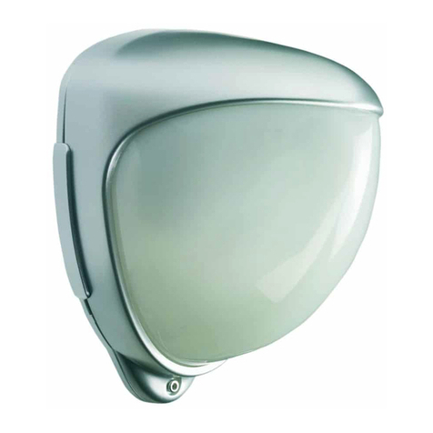
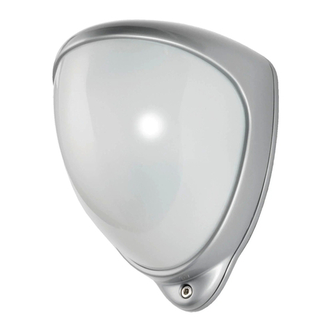
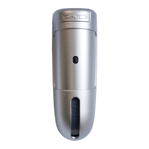
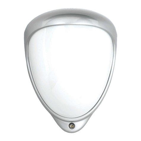
The RADIUS LUX is a combined
internal PIR detector with
additional lighting and heating
activator. It is compatible with all
standard alarm panels,
lighting controllers and solid state
relays.
The RADIUS LUX is supplied pre-
programmed ready to use. These
settings can be modified by the
installer using the rear program
button and front red and green
indicator.
Version DDE6
15 Metres over 140 Degrees - Multi-curtain lens
10 to 16 VDC at 11 mA reverse polarity protected
Digital - microprocessor controlled
Normally closed contacts rated at 100mA at 50 VDC
with 22 ohm 1/8W series resistor.
Normally closed contacts rated at 500mA at 50 VDC.
Negative switching at 25mA every time a detection takes place day or
night. Stays negative for the length of the 'A' timer after last detection.
Negative switching at 25mA with detection when dark. Stays negative
for the length of the 'S' timer setting after last detection.
Inhibited if the light level exceeds 1000 LUX unless in 24HR.
-10 to +50 Centrigrade
SPECIFICATIONS:
RANGE:
VOLTAGE:
PROCESSING:
ALARM:
TAMPER:
'A' OUTPUT:
Pulse count 1
'S' OUTPUT:
Pulse count 1
TEMPERATURE:
111096
1
BEAM PATTERN
2.5M
SIDE ELEVATION
15M
2
Example 1. To set the light level to 5 LUX.
First, choose the SELECTION and OPTION required from the table.
( ie. 4x GREEN flashes, 3x RED flashes ) :-
Press and HOLD the program button until the GREEN light flashes 4x in rapid
succession, then release the button. After a pause, the indicator will then carry
on to flash RED.
Count the RED flashes, and if they need to be changed press and HOLD the
program button ( within 3 seconds ) until the RED indicator flashes 3x in rapid
succession, then release the button.
After 3 seconds the GREEN indicator blinks once, the change is stored and the
unit exits from the program mode .
The program button is located inside the unit on the rear of the circuit board whilst
the RED and GREEN indicators can be seen from the front of the lens.
To familiarise yourself with the unit, first check the existing settings.
View the unit from the front and BE READY TO COUNT THE FLASHES.
Press the program button MOMENTARILY then :-
Count the number of GREEN flashes ( this represents the present selection )Count the
number of RED flashes ( this corresponds to the present option )
- see programming table.
After 3 seconds the GREEN indicator blinks once, and the unit exits the program
mode and functions normally.
Example 2. To set the 'S' TIME to 8 mins.
First, choose the SELECTION and OPTION required from the table.
( ie. 5x GREEN flashes, 5x RED flashes ) :-
Press and HOLD the program button until the GREEN light flashes 5x in rapid
succession, then release the button. After a pause, the indicator will then carry
on to flash RED.
Count the RED flashes, and if they need to be changed press and HOLD the
program button ( within 3 seconds ) until the RED indicator flashes 5x in rapid
succession, then release the button.
After 3 seconds the GREEN indicator blinks once, the change is stored and the
unit exits from the program mode.
a)
b)
c)
a)
b)
c)
TO RESET THE UNIT BACK TO FACTORY SETTINGS:
EITHER:
OR:
WHEN INSTALLING THE RADIUS LUX ENSURE THE WIRING
DOES NOT PRESS ON THE TAMPER SWITCH OR PROGRAM BUTTON.
Reset back to factory settings.
RED movement indicator has no pulse count.
Lighting activates with movement 24 hours.
RED indicator illuminates when the light level is too high for .the
RADIUS LUX to activate the room lighting.
The number of beams that have to be crossed to trigger the unit.
1 will give a fast response.
2 gives better immunity with good response.
3 gives highest immunity to false activations in poor environments
....but is less responsive.
Pass through areas when natural lighting is insufficient.
Normal office requirements when increased illumination is required.
Iinspection areas when bright illumination is required.
Will operate the lighting in response to movement 24 hours.
NPC:
24HR:
LUX:
PULSE COUNT:
LUX light level:
(as a guide)
3
Unplug the +/- 12VDC terminal block from the unit whilst
the power is connected.
Press and HOLD the program button whilst the terminal
block is
reconnected to the unit, then release the button.
Select the factory setting from the programming table
ie. 2x GREEN flashes, 1x RED flash
2.
20.
100.
24HR.
.
1x RANGE metres*
PULSE COUNT**
LED MONITOR
LUX light level*
'S' TIME mins*
812 15
234 5
OFF ON NPC
LUX
520 50 24HR
100
5
3218 12 16 24 32
2x
3x
4x
5x
GREEN SELECTIONS factory settings are highlighted
2
1
* = approx.
** = alarm output
and LED only
RED OPTIONS
'A' TIME mins* 08s 1 2 4 8 16 24 32
6x
1x 2x 3x 4x 5x 6x 7x 8x 9x
All programmed functions are saved if power is removed from the unit.
4
Mount indoors in a dry position on a rigid surface to avoid movement of the
detector. The multi curtain beam pattern allows the unit to be mounted
between 2 and 4 metres high without the need to align the beam pattern. If
the unit is mounted high the blind area below the detector will increase
( see beam pattern ). The ideal position for the unit is one which detects
movement across its field of view ( not towards the unit ) which will give
the best detection response.
As the detects a heat change in its field of view, AVOID:-
Radiated, convected heat sources, and ventilation ducts.
Direct and reflected sunshine.
Position the unit far enough away from light fittings to prevent excessive
heat or light affecting the normal operation of the unit.
TO SEPARATE THE :
(1) Slacken the screw at the base of the unit
DO NOT REMOVE.
(2) Ease the bottom of the front lens assembly forwards.
(3) Ease the assembly downwards.
Mount the rear mounting plate in the selected position using the supplied
screws/fixings. Avoid over tightening the screws or the rear mounting plate
will be distorted.
Standard alarm cable is recommended for all connections. Remove the outer
sleeving from the cable inside the case to make the connections more
flexible and easier to connect. The terminal blocks plug onto the circuit
board and can be removed to ease wiring if required.
Reverse the procedure when assembling the unit, taking care
NOT TO OVER TIGHTEN the base screw or trap wires against the tamper
switch or program button.
CEILING MOUNTING
CORNER MOUNTING
WALL MOUNTING LEAVE 10cm OF CABLE
REMOVE OUTER CABLE
SLEEVING INSIDE THE CASE
TO MAKE THE CONNECTIONS
MORE FLEXIBLE
SLACKEN SCREW ENOUGH TO FREE
FRONT ASSEMBLY
( DO NOT REMOVE )
VIEW OF REAR MOUNTING PLATE
A S
TAMPER ALARM
12VDC
PROGRAM
BUTTON
REAR VIEW OF CIRCUIT BOARD
TAMPER SWITCH
PROGRAM BUTTON
USED IN
CONJUNCTION WITH
THE FRONT LED
INDICATOR FOR
PROGRAMMING

Other GJD Security Sensor manuals

GJD Opal XL User manual

GJD

GJD Opal XL User manual

GJD D-TECT 1 User manual

GJD

GJD D-TECT 1 User manual

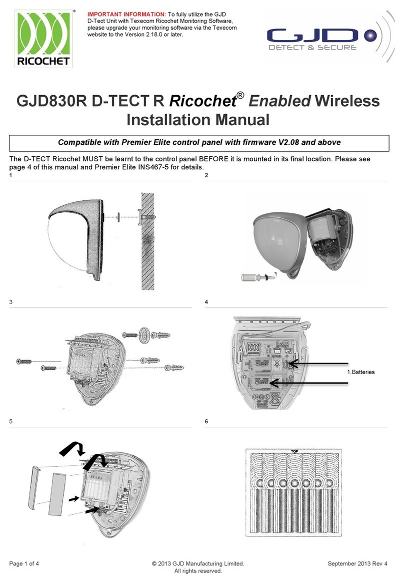
GJD D-TECT R Ricochet GJD830R User manual

GJD

GJD D-TECT R Ricochet GJD830R User manual

GJD D-TECT R Ricochet GJD830R User manual

GJD

GJD D-TECT R Ricochet GJD830R User manual

GJD GJD840R User manual

GJD

GJD GJD840R User manual

GJD D-TECT 60 User manual

GJD

GJD D-TECT 60 User manual

GJD D-TECT Dual AM User manual

GJD

GJD D-TECT Dual AM User manual

GJD Mini Opal User manual

GJD

GJD Mini Opal User manual

GJD D-TECT Pet Immune GJD370 User manual

GJD

GJD D-TECT Pet Immune GJD370 User manual

GJD D-TECT Dual ABS User manual

GJD

GJD D-TECT Dual ABS User manual

GJD GJD140 User manual

GJD

GJD GJD140 User manual

GJD D-TECT 3 IP GJD260 User manual

GJD

GJD D-TECT 3 IP GJD260 User manual

GJD D-TECT R Ricochet GJD850R User manual

GJD

GJD D-TECT R Ricochet GJD850R User manual

GJD MX25 User manual

GJD

GJD MX25 User manual

GJD D-TECT 1 HT User manual

GJD

GJD D-TECT 1 HT User manual

GJD D-TECT Pet Immune GJD370 User manual

GJD

GJD D-TECT Pet Immune GJD370 User manual

GJD D-TECT 40 IP User manual

GJD

GJD D-TECT 40 IP User manual

GJD D-tect Dual HT GJD362 User manual

GJD

GJD D-tect Dual HT GJD362 User manual

GJD MX2 User manual

GJD

GJD MX2 User manual

GJD D-TECT Universal Dual Tech User manual

GJD

GJD D-TECT Universal Dual Tech User manual

GJD D-TECT 1 HT User manual

GJD

GJD D-TECT 1 HT User manual

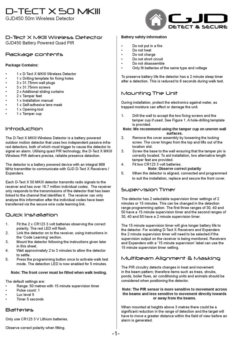
GJD D-TECT X 50 MKIII User manual

GJD

GJD D-TECT X 50 MKIII User manual

GJD D-TECT 2 IP User manual

GJD

GJD D-TECT 2 IP User manual

GJD Quad PIR MX20 HT User manual

GJD

GJD Quad PIR MX20 HT User manual

Popular Security Sensor manuals by other brands

Kopp INFRAcontrol R operating instructions

Kopp

Kopp INFRAcontrol R operating instructions

Waters ACQUITY UPC2 Overview and maintenance guide

Waters

Waters ACQUITY UPC2 Overview and maintenance guide

Haneco HIGHBAY-MS user guide

Haneco

Haneco HIGHBAY-MS user guide

DRC D 1000LF Operation manual

DRC

DRC D 1000LF Operation manual

ELREHA EGS CO2 SET manual

ELREHA

ELREHA EGS CO2 SET manual

FIBARO FGMS-001 operating manual

FIBARO

FIBARO FGMS-001 operating manual

Robus R100LEDCCT3E-01 instruction manual

Robus

Robus R100LEDCCT3E-01 instruction manual

Source Innovations Cordless Teth-Air user manual

Source Innovations

Source Innovations Cordless Teth-Air user manual

AJAX FireProtect 2 (CO) Jeweller user manual

AJAX

AJAX FireProtect 2 (CO) Jeweller user manual

Safescan 185-S Quick installation guide

Safescan

Safescan 185-S Quick installation guide

CAME SMA operating instructions

CAME

CAME SMA operating instructions

Extech Instruments DVA30 user guide

Extech Instruments

Extech Instruments DVA30 user guide

Topaz ES/LED/RW/B installation instructions

Topaz

Topaz ES/LED/RW/B installation instructions

2gig Technologies 2GIG-PIR1E-345 installation instructions

2gig Technologies

2gig Technologies 2GIG-PIR1E-345 installation instructions

AJAX GlassProtect user manual

AJAX

AJAX GlassProtect user manual

Cisco MERAKI MT12 installation guide

Cisco MERAKI

Cisco MERAKI MT12 installation guide

Velleman CS100N user manual

Velleman

Velleman CS100N user manual

BeeSecure BEE-MS manual

BeeSecure

BeeSecure BEE-MS manual

manuals.online logo
manuals.online logoBrands
  • About & Mission
  • Contact us
  • Privacy Policy
  • Terms and Conditions

Copyright 2025 Manuals.Online. All Rights Reserved.