manuals.online logo
Brands
  1. Home
  2. •
  3. Brands
  4. •
  5. CAME
  6. •
  7. Security Sensor
  8. •
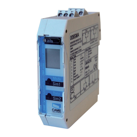
  9. CAME SMA User manual

CAME SMA User manual

Safety instructions
1
These devices and their accessories may only be operated in compliance with the operating instructions (intended use)!
These devices and their accessories may only be commissioned by trained and qualified personnel.
These devices may only be operated with the intended operating voltages and parameters.
If malfunctions occur that cannot be rectified, shut down the device and send it in for repair.
These devices are only allowed to be repaired by the manufacturer. Tampering and alterations are not permitted. This will invalidate all guarantee and
warranty claims.
The loop connection wiring to the loop detector must be twisted at least 20 times per meter.
Please wire the device in accordance with the terminal assignment. Make sure the terminals are assigned correctly.
1
LOOP DETECTOR
Doc mentazione
Tecnica
T20
rev. 3.0
01/2010
©CAME
CANCELLI
AUTOMATICI
119RT20-EN
SMA - SMA 2 - SMA 230
ENGLISH
Operating instructions for Installing an Start-up (Translation)
Mounting an electrical connection
SMA is mounted directly onto a standardized 35-mm mounting rail.
The terminals for all connections are coded pluggable terminals.
2
Supply voltage Loop connection
1-channel evice
Loop connection
2-channel evice Alerting Output 2n output
+/~
–/~
A1
A2
L3
L4
L3
L4
L5
L6
1
2
31
32
34
common
nc
no
14
11
12
common
nc
no
24
21
22
common
nc
no
Relay response to malfunctions (see chapter 6 Troubleshooting):
General
xplanation of the LCD display xplanation of the L D
Standard display
1-loop device
Standard display
2-loop device Control button Control button
1
12
Mode
Sim1
Data
Sim2
12
Loop 2,
output 2
xample:
Parameter «h»
set
Function
xample:
Time
function set
Loop 1, output 1
Info
Red: Start-up phase
Green: Operation
Red & green: Configuration
Flashing green: Loop activated
Flashing red: rror
Flashing red + green: Simulation
The settings of the devices in this chapter are shown and explained for the 1-loop device. The settings for loop 2 of a 2-loop device should be made using
the corresponding method.
1.Door/gate
systems
A malfunction causes
the output relay to be
released. The alarm
relay drops out.
2. Barrier
A malfunction causes
the output relay to pick
up. The alarm relay
drops out.
3. Quiescent
current
A malfunction causes the
output relay to be
released. The alarm relay
drops out.
4. Direction logic
(2-loop device
only)
A malfunction causes
the output relays to be
released. The alarm
relay drops out.
Parameters
1: Door an gate The assigned output relay picks up when the loop is activated and drops out when the loop returns to a non-activated condition.
2: Barrier The assigned output relay picks up when the loop is activated and drops out when the loop returns to a non-activated condition.
3: Quiescent current The assigned output relay drops out when the loop is activated and picks up again when the loop returns to a non-activated condition.
4: Direction logic Output 1 switches if an object moves from loop 1 to 2. Output 2 switches if an object moves from loop 1 to 2. Both loops must be
activated for a short time. The outputs are reset again when loop 2 returns to a non-activated condition. Both loops must have re-
turned to a non-activated condition for another direction detection.
0: Loop 2 Loop 2 / output 2 can be deactivated in a 2-loop device.
3Value an parameter setting options
LCD display and controls
3.1
Basic functions 0(see Table 4.1a for settings)
3.2
The relay picks up when the
loop is activated and drops
out when the loop is exited.
Loop
Relay
On delay:
The relay picks up after the
time t when the loop is acti-
vated and drops out when
the loop is exited.
Loop
Relay
tt
Off delay:
The relay picks up when the
loop is activated and drops
out after the time t when the
loop is exited.
Loop
Relay
tt
Activation pulse:
The relay picks up when the
loop is activated and drops
out again after the time t.
Loop
Relay
tt
Impulse by leaving the loop:
By leaving the loop,
the relay picks up after
the time t, relay drops out.
Loop
Relay
tt
The sensitivity 5(=Sensitivity) of the loop detector can be adapted in 9 stages: 51 = Lowest sensitivity, 59 = Highest sensitivity,
56 = Factory setting. The sensitivity setting depends on the frequencies (see chapter 3.6 Frequency).
In a device with 2 outputs, output 2 can be either activated or deactivated. In ProLoop 11, output 2 can also be set as an alarm output.
Four different frequencies F1, F2, F3, F4* can be set in order to avoid interference when using several loop detectors. These settings influence the
sensitivity (the sensitivity can be set in the range 1–7 for frequencies F1 to F3). F2 to F4 can be set for inductance < 150 µH and only F4 can be set for
inductance < 75 µH.
The direction logic function can only be used with a 2-loop device. Direction logic must have been set in the basic function (see chapter 3.2). Detection
can be performed from: ➝Loop 1 to loop 2 ➝From loop 2 to loop 1 ➝from both directions
Display after start-up:
1
Touch the «Mode» button once
to change to configuration
mode
Mode
Sim1
1
Display after start-up:
12
Touch the «Mode» button once
to change to configuration
mode
Mode
Sim1
1
Mode
Sim1
2
Loop 2 is
selected
Loop 1 is
selected
ASB (=Automatic Sensitivity Boost). ASB is required in order to be able to recognise trailer drawbars after activation.
Basic function 2 «Barrier systems» or 3 «quiescent current» must be set for this function.
P 1 = Protection against power tailure activated: The sensitivity is restricted to 1–5 and the time function to h.
Time functions 1, time unit 2 and time factor 3 (see Table 4.1a for settings)
3.3
Sensitivity 4 (see Table 4.1a for settings)
3.4
Automatic Sensitivity Boost ASB 5(see Table 4.1a for settings)
3.5
Frequency 6(see Table 4.1a for settings)
3.6
Direction logic7(see Table 4.1a for settings)
3.7
Output 2 8(see Table 4.1b for settings)
3.8
Protection against power failure 9(see Table 4.1a for settings)
3.9
1- loop evice
2- loop evice
2
Signal characteristics with protection against power failure active (Function 9 = 1)
3.9.1
For Activation (e.g. Barriers)
Basic function 0 = 2 Barrier systems
common
nc
no
common
nc
no
Without power Initialisation Free Occupied Free
For Safeguarding (e.g. Barriers, bollards)
Basic function 0 = 3 Quiescent current
Without power Initialisation Free Occupied Free
common
nc
no
common
nc
no
4Changeover from operation to configuration mo e
Function LCD
display
Button operation
functions
0- Basic function
1
Mode
Sim1
1- Time function
1
Mode
Sim1
2- Time unit
1
Mode
Sim1
This display does not
go out in time
function th (∞)
3- Time factor
1
Mode
Sim1
This display does not
go out in time
function th (∞)
4-Sensitivity
1
Mode
Sim1
5=Sensitivity
5-Automatic
Sensitivity Boost
ASB
1
Mode
Sim1
ASB stands for
Automatic Sensitivity
Boost
6-Frequency
1
Mode
Sim1
7-Direction logic
12
Mode
Sim1
Thisdisplay appears
onlywitha
2-loop device
8-Output 2
configuration
1
Mode
Sim1
9-Protection
againstpower
failure
Mode
Sim1
A-Operating mode
1
3
Data
Sim2
Data
Sim2
Data
Sim2
Data
Sim2
Data
Sim2
Notes
Door/gate
systems*
1
Barrier systems
1
Quiescent current
1
Direction logic
12
Only 2-loop device:
Loop 2+output 2
Deactivate: «1»
Activate: «0»*
2
∞*
1
On delay
1
Off delay
1
Activation pulse loop
1
Time function pulse
when loop is exited
1
0.1 second
1
1 second*
1
1 minute
1
1 hour
1
The time unit multiplied by
the time factor gives the set
time.
1*
1
Set value between 1 and 99 by
touching or holding the «Data»
button
6*
1
Set valuebetween1(lowest )
and9(highest sensitivity)by
touchingor holdingthe«Data»
button
Settingrestrictions:
Frequency F1-F3:Value1–7
Protectionagainst power
failure (with P1): Value1-5
Switchedoff*
1
Switchedon
1
Frequency F4*
1
Frequency F1
1
Frequency F2
1
Frequency F3
1
Both directions
12
Loop2to loop1
12
Loop1to loop2
12
Thedirectionlogic function
canonly beimplemented
with 2loops anda2-loop
device
Output 2 is
switchedoff
2
Output 2 is activated
2
Output 2 is
connectedas alarm
output (only possi-
ble with ProLoop11)
2
Loop+output 2 must beset
to «active»
Switched off*Switched on If parameter 9=P1
parameter 5 mustbe set to off
(5=A0 ).
Operating mode
1
rrormemory slot1rrormemory slot2rrormemory slot3rrormemory slot4
Possible displaysincaseof
error: seechapter 6 of these
operatinginstructions
Button operation
parameter
4.1 Configuration mode
Table 4.1a Settings
Table4.1b Different productvariants (setting options)
*Factory setting
Note on 2-loop device: After loop 1 has been set, the parameters for loop 2 are set (make the settings using the same procedure) and the settings are not shown in the table with the exception of the direction logic
SMA,SMA230
Loop 2 Output2Notes
1-loop device,2 relays –1-0/1*1 = Output2 on;0=Output2 off
SMA2
Loop 2 Output2Notes
2-loop device,2 relays active –Parameter8 isnotpossible and isnotdisplayed
deactivated1-0/0*1=Output2 on;0=Output2 off
Loop
Relay
Loop
Relay
tt
Loop
Relay
tt
Loop
Relay
tt
Loop
Relay
tt
4
If an error occurs, operating mode «A» and error display « » light up alternately and an error code such as 012 is displayed. The L D changes to red,
the 4 most recent errors are stored and can be interrogated.
Display 001 002 011 012 101 201 301 302 311 312
Error Interruption
Loop 1
Interruption
Loop 2
Short circuit
Loop 1
Short circuit
Loop 2
Under-
voltage
PROM
rror
Loop 1
too large
Loop 2
too large
Loop 1
too small
Loop 2
too small
Briefly pressing the «Data» button shows the last of 4 errors on the display. Another short press switches to the error before that,
and so on. When the button is pressed for the 5th time, the device switches back to automatic mode. If you press the «Data» button
for 2 seconds during the query, all error messages are deleted. The figure shows memory slot 1 in which error 001 Interruption loop
1 has been stored (example).
5Determination of the number of loop turns
6Troubleshooting
7Reset
8Most important technical ata
Mode
Sim1
2 seconds
Reset 1 (recalibration)
The loop(s) is/are recalibrated.
Mode
Sim1
8 seconds
Data
Sim2
Reset 2 (factory setting)
All values are reset to the factory settings (see Table 4.1a). The
loop(s) is/are recalibrated.
For conformity reasons, in any situation, the antenna factor defined as the loop surface multiplied by the number of turns
should not exceed NA = 20
max.
50 mm
For example, if L = 2m, a = 1m and the number of turns = 4, then the NA = 2x1x4 = 8 < 20.
Find hereafter the recommended values for the turns:
Area Number of turns
<3m24
3-5 m23
6-10 m22
Profondità della scanalatura
Loop
sealant
30 - 50 mm depending
on cable turns number
Clean and dry slots prior
to inserting cable
Supply voltage
SMA, SMA2
24 VAC –20 % to +10% 84 mA
24 VDC –10 % to +20% 84 mA
Supply voltage
SMA 230
94–240 VAC ± 10%, 50/60 Hz,
23 bis 12 mA
Power consumption max. 2 VA Loop resistance < 8 Ohm with connection wire
Loop in uctance max. 40–1000 µH,
ideally 80–300 µH Loop connection wiring max. 25 m 1,5 mm2
min. 20x/m
Output relay (loop) 240 VAC/2 A AC1 Output relay (alarm) 60 VAC, 0.3 A, AC1
Dimensions 22.5 x 94 x 88 mm (W x H x D) Operating temperature –20°C to +60°C
Connection type Plug-in terminals Storage temperature –40°C to +70°C
Protection class IP 30 Air humi ity <95% non-condensing
All ata checke with the maximum care. However, no libality is accepte for any error or omission.
The eclaration of conformity an other technical ocumentation are available on our website www.came.it – BUY-TO-SELL PRODUCT
CAME
CANC LLI AUTOMATICI S.P.A.
Via Martiri Della Liberta, 15
31030 Dosson di Casier
Treviso - ITALY
Phone (+39) 0422 4940
Fax (+39) 0422 4941
Assistenza Tecnica
Numero Verde
Phone 800 295830
Web: www.came.com
-Mail: [email protected]
6926-06-0288b01/10259416
www.came.com
Codicemanuale:119RT20-Nver.3.001/2010©CAM cancelliautomaticis.p.a.

Other manuals for SMA

2

This manual suits for next models

2

Other CAME Security Sensor manuals

CAME 001SIR215WL User manual

CAME

CAME 001SIR215WL User manual

CAME R Series User manual

CAME

CAME R Series User manual

CAME SADRIN 205 User manual

CAME

CAME SADRIN 205 User manual

CAME R Series User manual

CAME

CAME R Series User manual

CAME DXR20CAP User manual

CAME

CAME DXR20CAP User manual

CAME 806TF-0030 User manual

CAME

CAME 806TF-0030 User manual

CAME SIR310 User manual

CAME

CAME SIR310 User manual

CAME SMA User manual

CAME

CAME SMA User manual

CAME PXWDTVE User manual

CAME

CAME PXWDTVE User manual

CAME DBC 01 User manual

CAME

CAME DBC 01 User manual

CAME MR8570 User manual

CAME

CAME MR8570 User manual

CAME SMA User manual

CAME

CAME SMA User manual

CAME DXR20SAP User manual

CAME

CAME DXR20SAP User manual

CAME PXWIRCE User manual

CAME

CAME PXWIRCE User manual

CAME 001SDTEWL User manual

CAME

CAME 001SDTEWL User manual

CAME Security SIR215 User manual

CAME

CAME Security SIR215 User manual

CAME 001SDTE User manual

CAME

CAME 001SDTE User manual

CAME MR8534 User manual

CAME

CAME MR8534 User manual

CAME DXR10BAP User manual

CAME

CAME DXR10BAP User manual

Popular Security Sensor manuals by other brands

Banner Q5X quick start guide

Banner

Banner Q5X quick start guide

KNX GIRA operating instructions

KNX

KNX GIRA operating instructions

LaserLiner StarSensor 50 operating instructions

LaserLiner

LaserLiner StarSensor 50 operating instructions

Sulzer ABS CA 461 installation guide

Sulzer

Sulzer ABS CA 461 installation guide

Honeywell MIDAS-T-HTP quick start guide

Honeywell

Honeywell MIDAS-T-HTP quick start guide

iGuardFire iGuardStove User & Online Features Manual

iGuardFire

iGuardFire iGuardStove User & Online Features Manual

LEGRAND WattStopper LMUC-100-2 quick start guide

LEGRAND

LEGRAND WattStopper LMUC-100-2 quick start guide

ORORO TWIN-CITIES HEATED GLOVES manual

ORORO

ORORO TWIN-CITIES HEATED GLOVES manual

Jung Mini basic operating instructions

Jung

Jung Mini basic operating instructions

Kopp INFRAcontrol operating instructions

Kopp

Kopp INFRAcontrol operating instructions

Bosch Classic TriTech CM Series installation instructions

Bosch

Bosch Classic TriTech CM Series installation instructions

ZiLOG ZMOTION quick start guide

ZiLOG

ZiLOG ZMOTION quick start guide

Eldes EWP-EXT instruction manual

Eldes

Eldes EWP-EXT instruction manual

Raypak Latching Lockout Module C-5 product manual

Raypak

Raypak Latching Lockout Module C-5 product manual

Honeywell FG-730 installation instructions

Honeywell

Honeywell FG-730 installation instructions

Petzl NEWTON C73000 manual

Petzl

Petzl NEWTON C73000 manual

Lexing LX-MV-400 instructions

Lexing

Lexing LX-MV-400 instructions

Tiras MLT110 manual

Tiras

Tiras MLT110 manual

manuals.online logo
manuals.online logoBrands
  • About & Mission
  • Contact us
  • Privacy Policy
  • Terms and Conditions

Copyright 2025 Manuals.Online. All Rights Reserved.