Glacier bay HDGDUS4 User manual

THANK YOU
THANK YOUTHANK YOU
THANK YOU
We appreciate the trust and confidence you have placed in Glacier Bay through the purchase of this drinking ater
filtration system. We strive to continually create quality products designed to enhance your home. Visit us online to
see our full line of products available for your home improvement needs. Thank you for choosing Glacier Bay!
US Item# 1001 104 032
CAN Item# 1000803392
US Model # HDGDUS4
CAN Model # HCGDUS5
USE AND CARE GUIDE
ADVANCED DEFENSE DRINKING ATER
FILTRATION SYSTEM
Questions, problems, missing parts? Before returning to the store,
call Glacier Bay Customer Service
7 a.m. - 6 p.m., CS , Monday - Friday
1
11
1-
--
-800
800800
800-
--
-247
247247
247-
--
-1087
10871087
1087
HOMEDEPO .COM
HOMEDEPO .COMHOMEDEPO .COM
HOMEDEPO .COM/GLACIER
/GLACIER/GLACIER
/GLACIERBAY
BAYBAY
BAY
201-8401432 (rev 00)
System tested and certified by NSF International
against NSF/ANSI Standards 42 & 53.
See performance data sheet for details.
NSF
®

2
Table of Contents
Safety Information .................................2
arranty .................................................2
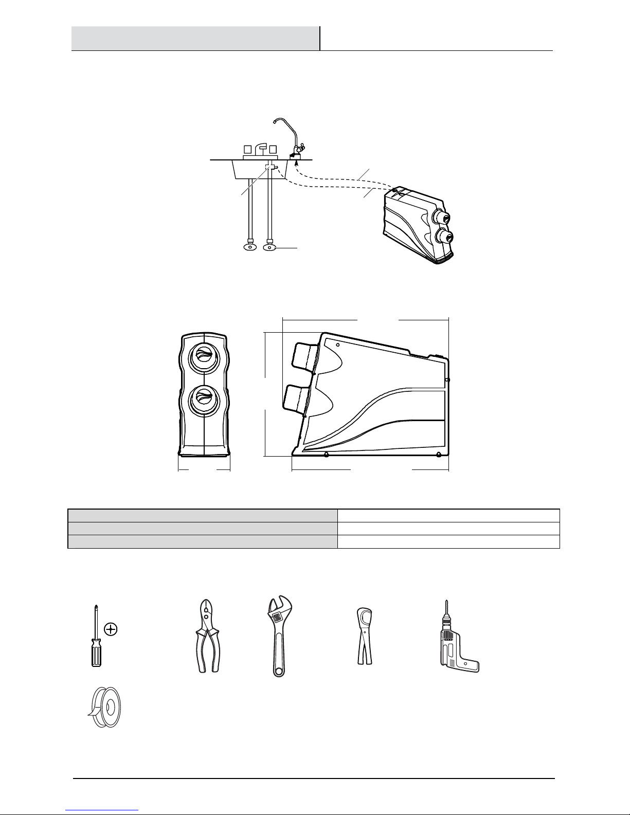
Pre-Installation ......................................3
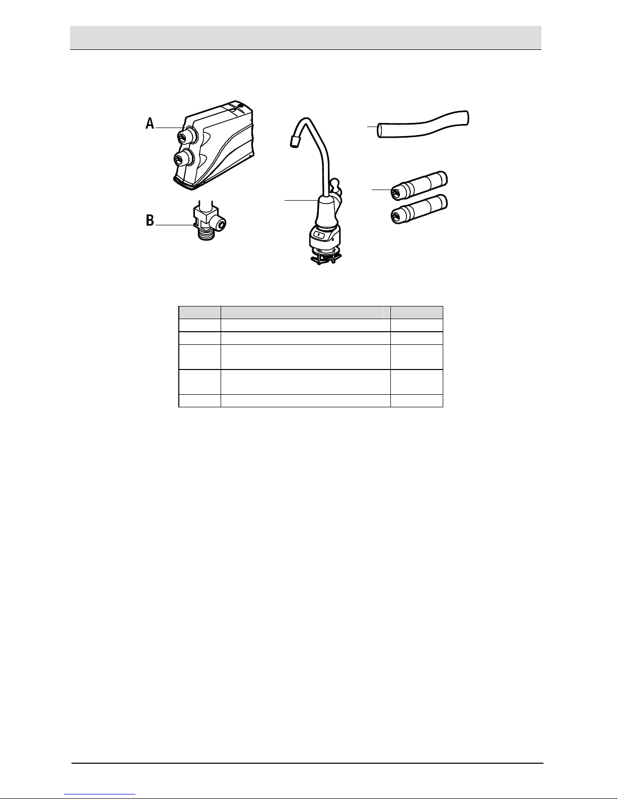
Installation .............................................5
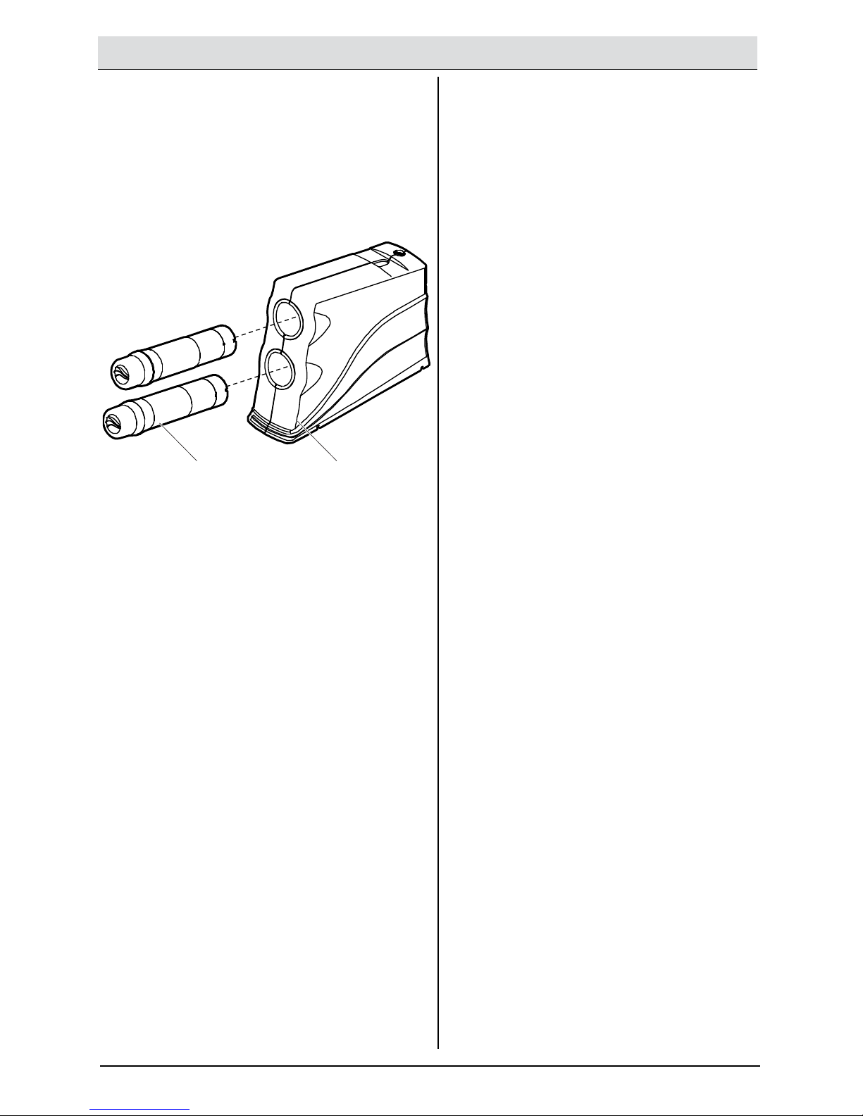
Filter Cartridges .................................... 8
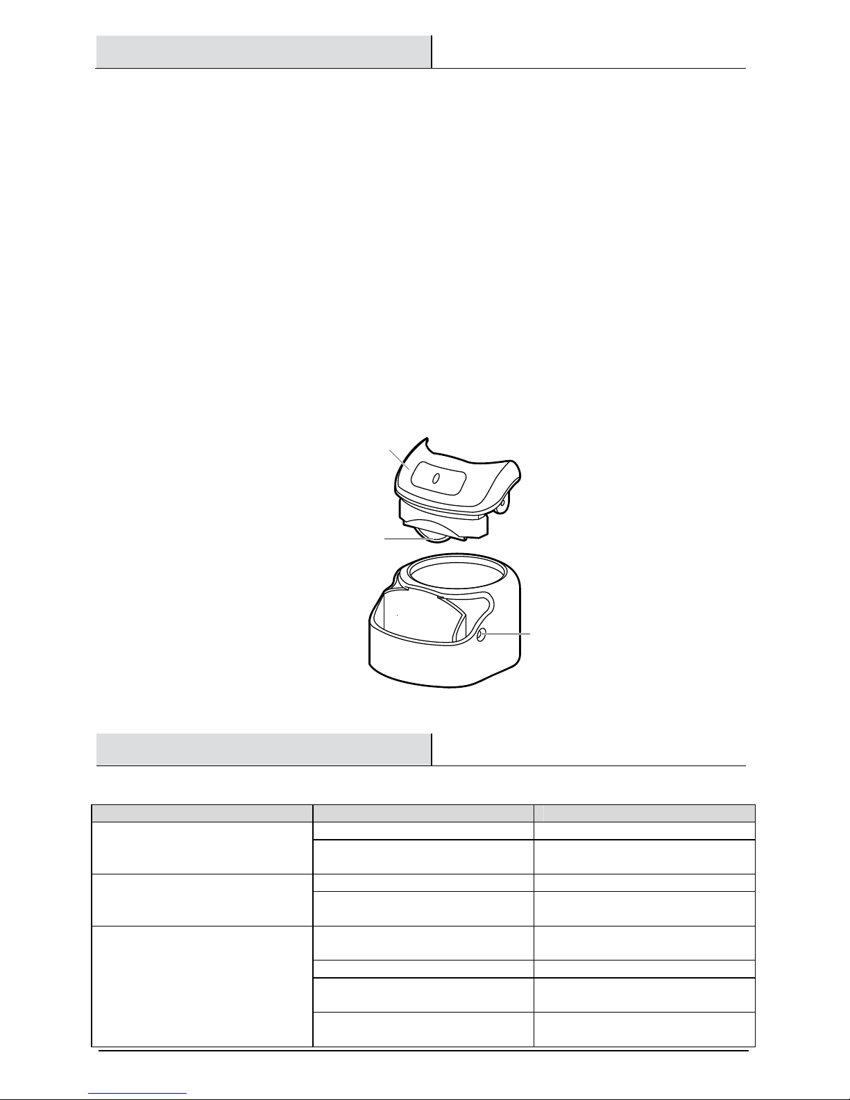
Faucet Timer and Battery ..................... 9
Troubleshooting .................................... 9
Service Parts ....................................... 10
Safety Information
Read all instructions before installing and using your
home water filtration system. Follow all steps
exactly to correctly install. Reading this manual will
also help you to get all the benefits from the
filtration system.
All plumbing must be completed in accordance with
national, state and local plumbing codes. Local code
information can be obtained at your local public
works department. In Massachusetts, plumbing
code 248 CMR 3.00 and 10.00 shall be adhered to.
Consult with your licensed plumber.
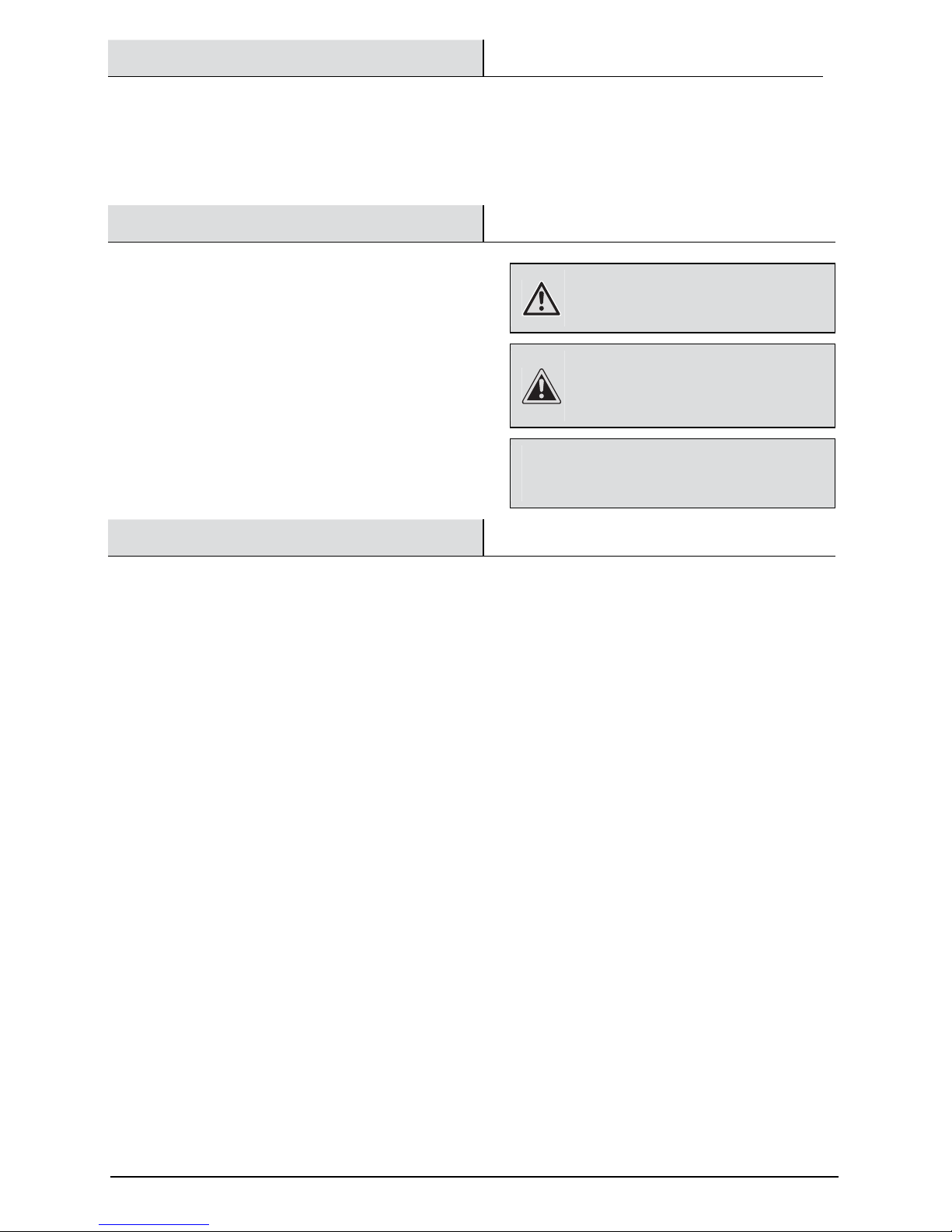
ARNING:
: :
: Do not use with water that is
microbiologically unsafe or of unknown quality
without adequate disinfection before or after the
system.
CAUTION:
: :
: Do not install the filtration system
outside, or in extreme hot or cold temperatures.
emperature of the water supply to the filtration
system must be between 40°F and 100°F. Do not
install on a hot water line.
NOTICE:
: :
: his filtration system works on water pressures of 30
psi (minimum) to 100 psi (maximum). If your house water
pressure is over the maximum, install a pressure reducing valve
in the water supply pipe to the filtration system.
arranty
GLACIER BAY WA ER FI
GLACIER BAY WA ER FIGLACIER BAY WA ER FI
GLACIER BAY WA ER FIL RA ION SYS EMS
L RA ION SYS EMS L RA ION SYS EMS
L RA ION SYS EMS -
--
-
WARRAN Y
WARRAN YWARRAN Y
WARRAN Y
Glacier Bay Water Filtration Systems are manufactured under the highest standards of quality and workmanship.
Glacier Bay Water Filtration Systems warrants to the original purchaser that this system will be leak and drip free
during normal domestic use for a period of one (1) year from date of purchase. If this system should ever develop a
leak or drip Glacier Bay Water Filtration Systems will free of charge provide the parts necessary to put the system
back in good working condition. A replacement for any defective part will be supplied free of charge for installation
by the purchaser. Defects or damage caused by use of other than authorized parts are not covered by this warranty.
his warranty shall be effective from date of purchase as shown on purchaser’s receipt. Glacier Bay Water Filtration
Systems shall be installed per the manufacturer’s installation instructions and specifications. Some states do not
allow limitations on how long a warranty lasts, so the above limitation may not apply to you. his warranty is valid
for the original purchaser only and excludes industrial, commercial, or business use of the product, product misuse,
and product damage due to installation error, whether performed by a contractor, service company, or yourself.
Glacier Bay Water Filtration Systems will not be responsible for labor charges or for damage incurred during
installation, repair or replacement, nor for incidental or consequential damages. Some states, provinces and nations
do not allow the exclusion or limitation of incidental or consequential damages, so the above exclusions or
limitations may not apply to you. Glacier Bay Water Filtration Systems will advise you of the procedure to follow in
making warranty claims.
Simply write to Glacier Bay Water Filtration Systems at the address below. Explain the defect and include proof of
purchase and you name, address and telephone number or you can also call us at 1-800-247-1087.
U.S.A Canada
Glacier Bay Water Filtration Systems Glacier Bay Water Filtration Systems
2455 Paces Ferry Road, N.W. 900-1 Concorde Gate
Atlanta, GA 30339-4024 oronto, ON M3C 4H9

3 HOMEDEPO .COM/GLACIERBAY
Please contact 1-800-247-1087 for further assistance.
Pre-Installation
INS ALLA ION LOCA IO
INS ALLA ION LOCA IOINS ALLA ION LOCA IO
INS ALLA ION LOCA ION
NN
N
Install the water filtration system on the cold water supply pipe, under the kitchen and/or bathroom sink, to filter the
cold drinking water. Refer to this diagram:
DIMENSIONS
DIMENSIONSDIMENSIONS
DIMENSIONS
SPECIFICA IONS
SPECIFICA IONSSPECIFICA IONS
SPECIFICA IONS
Minimum
Minimum Minimum
Minimum –
––
–
Maximum Supply Water Pressure
Maximum Supply Water PressureMaximum Supply Water Pressure
Maximum Supply Water Pressure
30 – 100 PSI (207 – 689 kPa)
Minimum
Minimum Minimum
Minimum –
––
–
Maximum Supply Water emperature
Maximum Supply Water emperatureMaximum Supply Water emperature
Maximum Supply Water emperature
40 - 100°F (5 - 38°C)
Inlet
Inlet Inlet
Inlet –
––
–
Outlet
OutletOutlet
Outlet
3/8 in. quick connect fittings and tubing included
OOLS REQUIRED
OOLS REQUIREDOOLS REQUIRED
OOLS REQUIRED
Phillips
screwdriver
Pliers
Adjustable
wrench
ubing
cutter
Drill and 1-1/4
in. drill bit
Sealant tape
SINK
Faucet
Yellow water IN
H
O
COLD
Shutoff valve
Supply fitting
Blue water OU
5 in.
12 in.
16 in.
15 1/8 in.

4
Pre-Installation (continued)
PACKAGE
PACKAGE PACKAGE
PACKAGE CON EN S
CON EN SCON EN S
CON EN S
Part
PartPart
Part
Description
DescriptionDescription
Description
Quantity
QuantityQuantity
Quantity
A Filtration system 1
B Water supply fitting 1
C Filtered water faucet for
sink/countertop mounting
1
D 3/8 in. tubing (used for all
connections)
1
E Filter cartridge 2
C
D
E

5 HOMEDEPO .COM/GLACIERBAY
Please contact 1-800-247-1087 for further assistance.
Installation
1
Connecting the feed water
Connecting the feed water Connecting the feed water
Connecting the feed water
supply
supply supply
supply fittings
fittingsfittings
fittings
Check and comply with local plumbing codes as you
plan and install a cold feed (supply) water fitting.
he
fitting must provide a leak-tight connection to the
water filter 3/8 in. tubing (D). A typical connection
using the water supply fitting (B) is shown in Figure
A. An optional connection using standard plumbing
fittings (not included) is shown in Figure B.
Installation using the Fitting (Figure A):
□Close the water shut off valve that is
immediately before the supply fitting and open
faucets to drain water from the cold water pipe
from the sink.
□Remove the nut that connects the cold water
faucet to cold water plumbing.
□hread the water supply fitting (B) onto the pipe
and reconnect the nut to the bottom of the
fitting.
Installation using Optio
nal Pipe Fittings (compression
type shown – Figure B):
□urn off the water supply and open a faucet to
drain the pipe.
□Install a fitting on the cold water pipe to adapt
to the 3/8 in. OD tubing.
□If threaded fittings are used, be sure to use pipe
joint compound or
thread sealing tape on outside
threads.
l
Figure B
Figure A
B
D
Cold water
pipe
hread sealing
tape on threads
Cold water
faucet stud
Cold water
shutoff
Cold water
shutoff
Ferrule
Cold water
pipe
3/8 in.
Compression
fitting Insert
3/8 in. tubing
to W
ater Filter
inlet

6
Installation (continued)
2
Installing the faucet
Installing the faucetInstalling the faucet
Installing the faucet
IMPORTANT:
: :
: o avoid damaging the sink, consult
a qualified plumber or installer for drilling procedures
in porcelain or stainless steel. Special drill bits are
made for this.
Before you begin, ensure there is room
underneath
the sink or countertop so you can
make the needed
connections. If drilling
is required in the sink top or
countertop next to the sink, make a 1-1/4 in. dia.
(minimum) hole for the faucet (C).
□Insert one end of the blue tube into the faucet
(C) (see Step 3 – Connecting the tubes). Feed
the other end of the blue tube through the
mounting hole.
□Slide the toggle bolts through the mounting
hole until the faucet (C) base is square against
the mounting surface (sink or countertop).
ighten the toggle bolts to secure the base flat
on the mounting surface. Do not over-tighten.
□urn the faucet 1/4 clockwise to attach the
faucet (C) to the base.
3
Connecting the tubes
Connecting the tubesConnecting the tubes
Connecting the tubes
Remove and discard the protective foam plugs (if
present) before connecting tubes.
□
Allowing some slack, measure and cut a length
of 3/8 in. tubing (D) to connect between the
supply fitting and the filter system inlet. Cut
the ends of the tubing square.
□Insert tubing all the way into the supply fitting
and inlet fitting. Pull on the tubing to be sure
that it is securely set in the fittings.
□Repeat the first two bullets to connect the
tubing from the faucet to the filter system
outlet.
ubing Connecti
ubing Connectiubing Connecti
ubing Connection (all push
on (all pushon (all push
on (all push-
--
-in fitting
in fittingin fitting
in fittings):
s):s):
s):
his system includes push-in fittings for quick
tubing connections. If working with the fittings, do
the following:
□Cut the end of the tubing square. Inspect the
end (about 1 in.) of the tubing to be sure there
are no nicks, scratches or other rough spots. If
needed, cut the tubing again.
□Push tubing through the collet and through the
fitting. Full engagement is 3/4 in. length of
tube into the fitting. If tubing other than
supplied with the system is used, be sure it is
of high quality, exact size and roundness with
a smooth surface.
C
1/4 tu
rn to connect
faucet to base
oggle bolt
Screw
Faucet base
Rubber w
asher
Hole in sink
or counter
End of tubing round and smooth,
with no cuts, nicks or flat spots
Correct full 3/4 in.
engagement
Tubing correctly cut and connected
Incorrect partial
engagement
To disconnect, push the collet inward and
hold with a finger while pushing the tubing out:
Remove and discard foam plugs
Foam plug
Push
in
fitting

7 HOMEDEPO .COM/GLACIERBAY
Please contact 1-800-247-1087 for further assistance.
Installation (continued)
4
Installing the filter cartridges
Installing the filter cartridgesInstalling the filter cartridges
Installing the filter cartridges
5
Completing the installation
Completing the installationCompleting the installation
Completing the installation
□Remove the plastic cap from the filter cartridges (E).
□Install the filter cartridges (E) into the two holes in
the filter body. Note the filter cartridges are labeled
Filter 1 and Filter 2. urn clockwise to tighten. Do
not over tighten.
□Open the shutoff valve that you closed at the
beginning of this installation.
□Open the filtered water faucet (C) to purge air
from the system. When the water runs smooth
with no bubbles or spurting close the faucet
(C) and check the installation for leaks.
□Open the filtered water faucet (C) and let
water run for 10 minutes to rinse system.
AE

8
Filter Cartridges
FIL ER CAR RIDGE LIF
FIL ER CAR RIDGE LIFFIL ER CAR RIDGE LIF
FIL ER CAR RIDGE LIFE
EE
E
he filter cartridge contains activated carbon, a black powder.
When new, open the filtered water faucet and allow fine, carbon particles to purge from the cartridge.
Close the faucet when you no longer see the “fines” (carbon particulates) in the filtered water, or approximately 10
minutes. It is recommended to replace the battery and filter cartridges every six months of use. here are several
variables that determine how long a cartridge will last. hese include:
1. How much water you use, and
2. How much sediment, taste and/or odor, or other unwanted substance, is in the water.
Use the following information as a guide. However, no matter which type of filter cartridge you are using, you will
know it is time to replace it when you first notice the return of the unwanted substance in your water.
Glacier Bay Advanced Defense Water Filtration System model HDGDUS4/HCGDUS5 with replacement filter element
pack HDGDUF4/HCGDUF5 conforms to NSF/ANSI 42 and 53 for the specific performance claims as verified and
substantiated by test data. he rated capacity for this system is 270 gallons (1022 liters) at a rated service flow of
0.5 gpm (gallons per minute).
FIL ER CAR RIDGE REP
FIL ER CAR RIDGE REPFIL ER CAR RIDGE REP
FIL ER CAR RIDGE REPLACEMEN
LACEMENLACEMEN
LACEMEN
1. urn the filter cartridges counterclockwise to remove and dispose of them properly.
2. Install the new filter cartridges by turning them clockwise.
3. Remove and replace the timer battery. See the Changing the Faucet Battery section for more information.
he filter cartridge contains activated carbon, a black powder. When new, open the filtered water faucet and allow
the fine carbon particles to purge from the cartridge. Close the faucet when you no longer see the “fines” in the
filtered water, or approximately 10 minutes.
Turn filter cartridge
counterclockwise to remove
Turn filter cartridge
clockwise to install

9 HOMEDEPO .COM/GLACIERBAY
Please contact 1-800-247-1087 for further assistance.
Faucet Timer and Battery
FAUCE IMER
FAUCE IMERFAUCE IMER
FAUCE IMER
Inside the faucet base is a battery-operated 6 month timer.
An amber LED indicator is also located in the front of the faucet base. his LED flashes continuously after 6 months
have passed. his indicates that it is time to replace the battery and filters.
CHANGING HE FAUCE
CHANGING HE FAUCE CHANGING HE FAUCE
CHANGING HE FAUCE BA ERY
BA ERYBA ERY
BA ERY
o change the battery, complete the following steps:
1. Loosen the screw on the right side of the faucet base.
2. Press the battery housing upwards from the faucet base until it releases from the base.
3. Replace the battery (CR 2032 or equivalent). Place battery into the holder with the positive (+) side
facing the back of the holder.
4. When the battery is first replaced, the light in the base will flash six times and turn off. his indicates
the battery is fully charged. After the six flashes, the timer enters the 6 month time cycle. If it
repeatedly flashes two times, the battery is weak and needs to be replaced.
5. Re-install the battery housing and firmly tighten the mounting screw.
Troubleshooting
Problem
ProblemProblem
Problem
Probable
Probable Probable
Probable Cause
CauseCause
Cause
Solution
SolutionSolution
Solution
he water tastes bad and has an
odor.
he filters are expended. Replace the filter cartridges.
he system is contaminated. Sanitize the system. Call 1-800-247-
1087 for instructions.
Faucet LED indicator light does not
function after a battery change.
he battery is dead. Replace the battery.
he battery is not installed correctly. Install the battery correctly, paying
attention to the polarity.
Water leaks at the push connect
fittings.
he tubing is not pushed in all the
way.
Push the tubing in all the way into
fittings.
he tubing is not cut square. Cut the tubing square.
he tubing is nicked. Remove the nicked portion and
reinsert the tubing into the fitting.
he outer tubing surface is not
smooth.
Remove the rough portion, and
reinsert the tubing into the fitting.
Battery housing
Screw
Battery
negative (-) side
facing the front

10
Service Parts
Key
Key Key
Key
Number
NumberNumber
Number
Part Number
Part NumberPart Number
Part Number
Description
DescriptionDescription
Description
Key
Key Key
Key
Number
NumberNumber
Number
Part Number
Part NumberPart Number
Part Number
Description
DescriptionDescription
Description
1 119-8600048 Faucet with base
and electronics
6 1073-23-02 Cabinet, right
2 1073-23-01 Cabinet, left 7 HDGDUF4/HCGDUF5 Replacement filter
cartridge, 2-pack*
3 1073-23-HC Head assembly
(includes #5)
8 7228536 ee, feed adapter
4 1073-23-05 Elbow fitting 9 1073-22-09 3/8 x 3/8 in. union,
yellow
5 3/8 x 3/8 in.
coupler
** 7157280 ubing, 3/8 in. x
20 ft., white
*Please purchase replacement cartridges from the retailer where you purchased this system.
** his tubing is not included. ubing lengths for remote installation, direct replacement for colored lengths of
tubing.

Questions, problems, missing parts? Before returning to the store,
call Glacier Bay Customer Service
7 a.m. - 6 p.m., CS , Monday-Friday
1
11
1-
--
-800
800800
800-
--
-247
247247
247-
--
-1087
10871087
1087
HOMEDEPO
HOMEDEPOHOMEDEPO
HOMEDEPO .COM
.COM.COM
.COM/
//
/GLACIERBAY
GLACIERBAYGLACIERBAY
GLACIERBAY
Retain this manual for future use.
Manufactured by
Ecodyne Water Systems
1890 Woodlane Drive
Woodbury, MN 55125
This manual suits for next models
1
Table of contents
Other Glacier bay Water Filtration System manuals