GLAZING VISION Pitchridge User manual

203-INST-UK-001 v1.0 –02 Aug 2022
www.glazingvision.co.uk
+44 (0)1379 658300
Installation Manual
Pitchridge

203-INST-UK-001 v1.0 –02 Aug 2022
Section Description
Page
Introduction
3
Safety Information
4
Pre-Installation Preparation
6
Preparation of the Roof
8
Installation Procedure
11
Interior Finishing
20

203-INST-UK-001 v1.0 –02 Aug 2022
Introduction
Thank you for purchasing a Glazing Vision Pitchridge. In order to ensure that it gives you many years of service it is important that
before commencing any work you read these instructions fully and ensure that they are strictly followed for a successful and trouble-
free installation.
We recommend that the installation should be undertaken by your roofing contractor, Glazing Vision recommends an NFRC
registered contractor. This will ensure a reliable product and enable the property owner to benefit from a 5-year warranty on the
product. It should be noted that an installation by non-approved installers will result in a reduced warranty period of just 2 years.
By following the correct installation procedure, a reliable and high performing end result is guaranteed. The critical operations that
can lead to problems if not done correctly are the lifting, preparation of the supporting structure, ensuring that the product is
mounted in the correct orientation and ensuring the correct line and level when mounting. Taking the time to carry out these
operations correctly will ensure that the product does not twist or distort making sure that the installed product has no undue
stresses in the frame or glass.
Care should be taken when working on the product, avoiding accidental damage, and ensuring product reliability.
Should you have any queries beyond this manual please do not hesitate to contact Glazing Vision.

203-INST-UK-001 v1.0 –02 Aug 2022
Safety Information
Installation of your roof window may involve working at heights, working at an unusual angle, being in unfamiliar locations or all of
these. Before work is commenced, stop, and consider the best way to carry out the task and what hazards you might encounter.
Let our experts carry out your routine maintenance with a maintenance contract.
+44 (0)1379 658300
These products can be very heavy. Extreme care must be taken during handling and installation. Full
consideration should be given to how you will safely transport your roof window product from the delivery
vehicle to the installation location. Glazing Vision strongly recommends that specialist, mechanical lifting
equipment is employed.
Consider:
•The weight(s) of the product purchased.
•How you will safely transport your roof window product from the delivery vehicle to the installation
location.
•All lifting methods and equipment required for safe installation to eliminate manual handling.
•How you will safely access the area to carry out installation.
•Any openings, voids or unprotected edges that might pose a significant risk whilst working at height.
•Use of scaffolding with all appropriate edging, rails, and inspection certification.
•If specialist access or equipment is required e.g., a fall arrest system.
•What personal protective safety equipment (PPE) is required for working at height –e.g., harness.
•Methods for safe working, for example, to avoid falling from height, reducing manual handling and
so as not to drop equipment.
•How you will transport tools and other equipment to the installation area.
•The number of persons required to assist with safe installation.
•The competence, capability, and experience of the installation team to safely carry out the task.
•Impact of weather on safe installation, especially driving rain and high winds.
If in doubt, please contact Glazing Vision for assistance.
Anticipated hazards may include:
•Falls from height
•Working with specialist lifting equipment or third-party lifting
•Manual handling injury
•Equipment falling from height
•Slips, trips, and falls
•Fragile roof areas.
•Finger or clothing entrapment under unit, in mechanical or moving parts
•Impact of weather conditions
•Competence of personnel
Do not attempt to repair, move, or dismantle the product unless suitably competent and qualified to do so,
with the appropriate safety measures in place. Any repairs and/or movement of the product may invalidate
the warranty. Please seek advice from Glazing Vision.

203-INST-UK-001 v1.0 –02 Aug 2022
Warning
The following warnings are here to prevent personal injury and damage to the product. Please follow them explicitly.
General:
•The product must be professionally installed and commissioned in accordance with this manual before it is used.
•Glazing Vision strongly recommends that any work is carried out by suitably qualified individuals (e.g., NFRC registered
contractors, Glazing Vision Engineers or Approved Installers, or an experienced service engineer).
•Glazing Vision strongly recommends that specialist, mechanical lifting equipment is employed.
•Use the product only for its intended purpose.
•Regular cleaning and maintenance must be carried out according to guidelines.
•A safe working platform must be provided for any installation/maintenance work carried out. This includes suitable edge
protection.
•Glazing Vision cannot be held responsible for damage incurred during the lifting and transportation of the product to the
installation location (please refer to terms and conditions of sale).
Pre-Installation:
•Glazing Vision products are heavy, fragile and of awkward shape and size. There may be uneven weight distribution due to
the materials used and their design.
•The weight(s) of each individual product (or product section) will be clearly marked on the product and will be
communicated to clients before despatch of goods.
•Never install any product showing signs of damage. If in doubt consult Glazing Vision for advice.
•Please dispose of the packaging material for this product in a considerate manner. Cardboard and wood items are widely
recycled.
During Use:
•Do not walk or sit on the unit.
For more information or assistance please contact Glazing Vision.

203-INST-UK-001 v1.0 –02 Aug 2022
These products can be very heavy. Consideration should be given to getting the product onto the roof safely and
extreme care taken during installation.
Points to Note Prior to Commencing Installation
1. The Pitchridge should arrive on site in undamaged packaging, which includes a wooden build frame/blocks, cardboard,
polyfoam glass protection and low tack tape. Please inspect for damage to packaging and/or product and advise Glazing
Vision of any damage or shortfall within 48 hours from signing the receipt of your delivery.
2. Enclosed within the box containing this manual will be the required number of fixing woodscrews and a number of plastic
packers, as well as some silicone and other required materials and any additional optional items selected at the time of
order.
Standard Installation Hardware
Enclosed within the hardware box for each unit you should find at least the following:
Stainless steel woodscrews
Plastic horseshoe packers
(Various sizes)
Low modulus silicone
Butyl tape
(50 mm wide)
Joint Cap x2
External Joint cover
Flashing Kit
If a flashing kit has been specified, the following items should also be included:
Lead sheet
Cill flashing (450 mm wide)
Lead for soakers (450 mm wide)
Roofing underlay
Jamb aprons (1 m wide)
Butyl tape
(50 mm wide)

203-INST-UK-001 v1.0 –02 Aug 2022
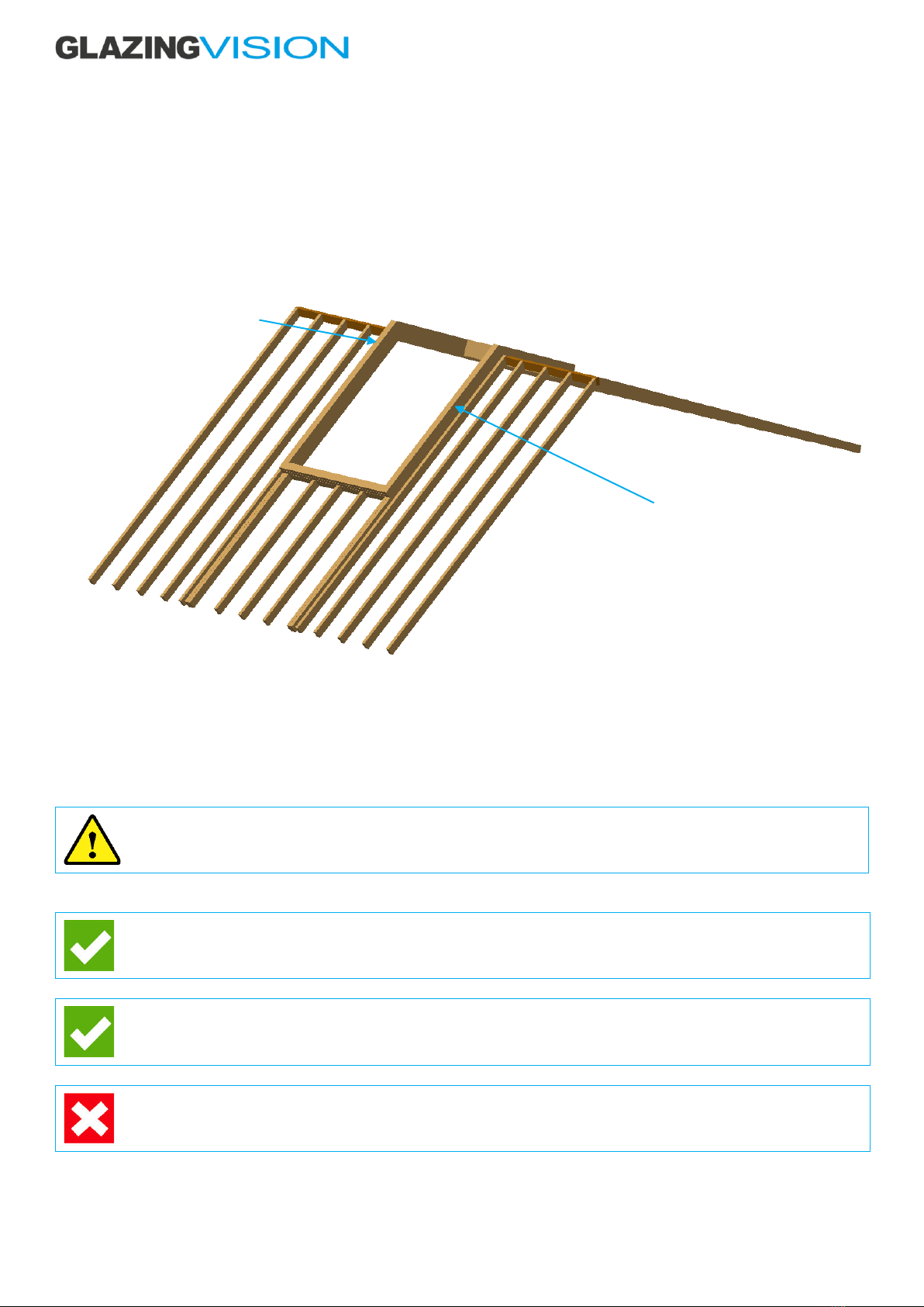
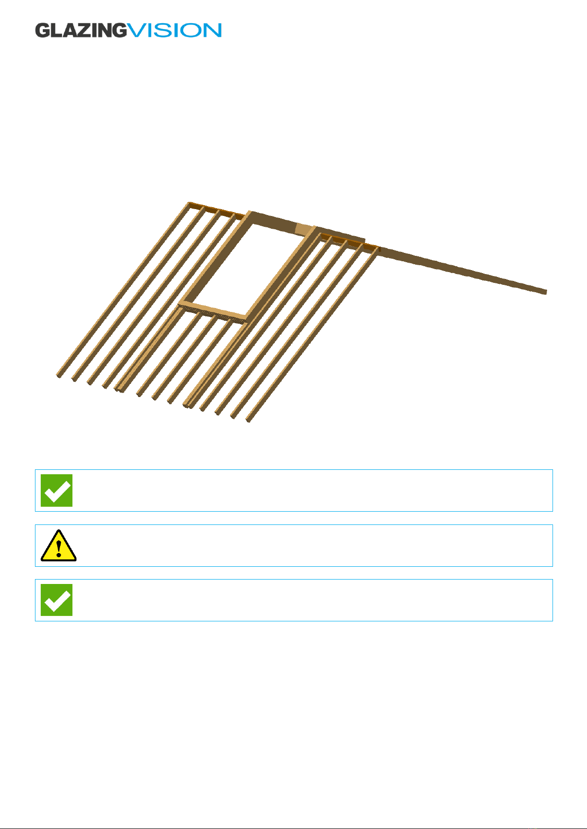
3. The supporting structure must already be in place for the product. The dimensioning of the product will have taken into
consideration the dimensions of the supporting structure including all weathering. More information about supporting
structure construction can be found in Glazing Vision’s sales drawings. Please note that a minimum distance of 140mm
from the structural opening to any surrounding structured must be felt on all sides. Sufficient room for installation
(including weathering) and maintenance must also be allowed for.
4. It is important to consider the type of tile or other roof finish to be used. The opening in the roof should ideally be positioned
so that you get a full tile at the top and at the bottom of the product, avoiding the need to cut tiles down.
5. It is important to ensure that the area of installation is suitably prepared. The area surrounding the supporting structure
should be clear to provide safe access during the installation works. It will be necessary to work on the outside and
therefore suitable provisions should be made for safe handling of the product, including all relevant personal protective
equipment (PPE) and safety systems for working at heights.
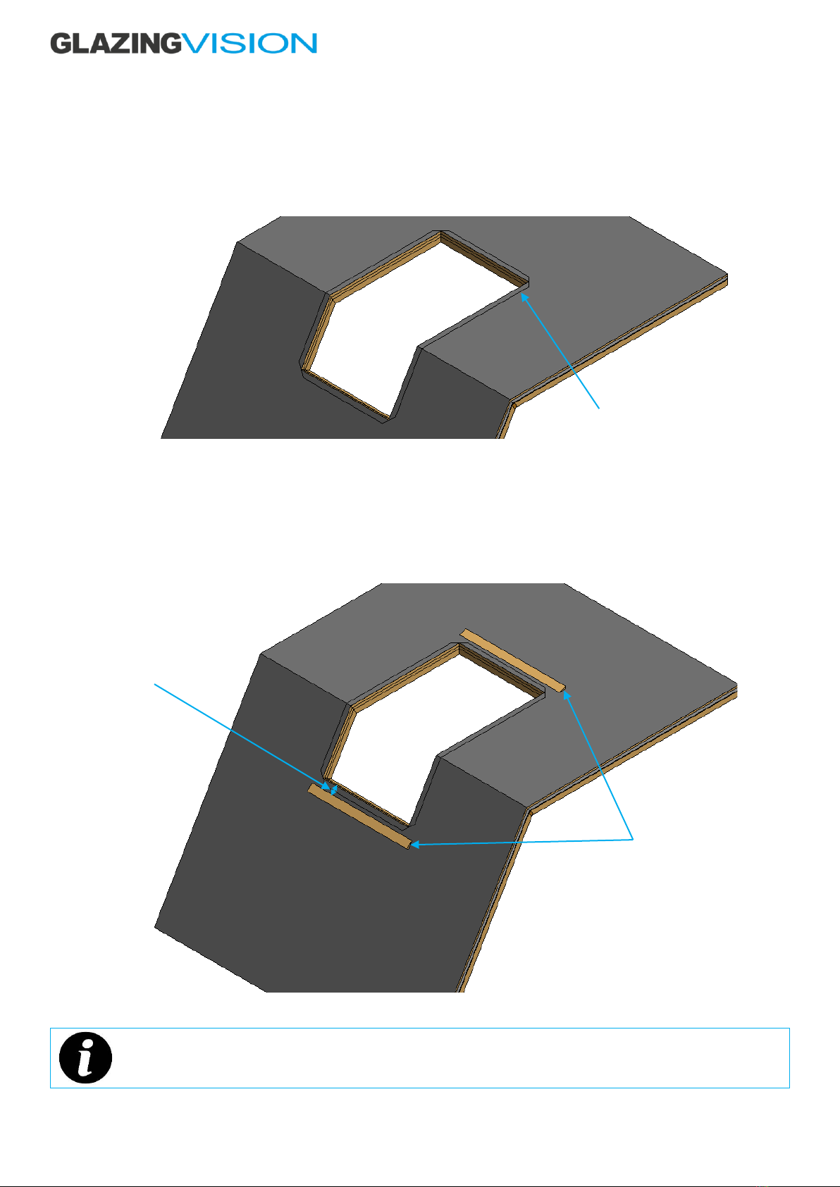
6. Before starting installation, Glazing Vision advises that the physical supporting structure dimensions are cross-checked
with those given for the order, to ensure the product will fit. The supporting structure will need to be within ± 10 mm of the
ordered size (measured across the flats). The top surface of the supporting structure should be flat without undulations
greater than ± 2 mm. Also check the diagonals to ensure that the supporting structure has been constructed square. The
supporting structure must be weathered as per the sales drawings. If using any metallic waterproofing material, take care
when applying it to the product/supporting structure, as if done incorrectly it can cause a thermal bridge which can lead
to internal condensation and invalidate the product warranty.
7. These products can be very heavy. Glazing Vision strongly recommends that a structural engineer is consulted when
designing the structure(s) that will support the product and the surrounding structure. Nothing in this manual or on Glazing
Vision’s sales drawings constitutes a structural proposal.
8. Preparation of the roof prior to installation will vary depending on roof type and roofing materials. A few common scenarios
are included in this manual. Please follow the applicable steps for your configuration. Glazing Vision strongly recommends
that a ‘dry run’ (without any silicone or butyl) is completed before committing to the final installation.
Sales Drawings
Sales drawings for the Pitchglaze can be obtained by downloading them from Glazing Vision’s website
(www.glazingvision.co.uk/resources) or by contacting Glazing Vision.
Sales drawings should accompany this installation manual. If you do not have them then do not continue the
installation without them.

203-INST-UK-001 v1.0 –02 Aug 2022
Preparation of the Roof
Preparation of the Roof –Raised Installation
Typically for warm-roof construction –the product will sit on a frame built up from the rafters.
Sales drawings:
Installation: 203-SDD-UK-001
Fixing dimensions: 203-SDD-UK-003
Figure 1 –Example of raised installation
When preparing rafters, consider how the insulating sarking and the ends of the battens will be supported at the jambs of the
product. Study the sales drawings of the Product carefully when designing the size of the aperture and spacers. Figure 1 is for
illustrative purposes only and may not be suitable for your installation.
These products can be very heavy. Glazing Vision strongly recommends that a structural engineer is consulted when
designing the structure(s) that will support the product and the surrounding roof. Nothing in this manual constitutes
a structural proposal.
Before continuing onto the installation instructions:
The raised frame that will support the product, and the surrounding rafters and horizontal trimmers, should be
complete and in place.
The insulating sarking (the insulation installed outside the rafters), and the counter-battens of the surrounding roof
should be complete and in place.
The surrounding roof should not yet be felted or battened; this will be covered in the installation instructions.
Spacers added to raise
the product away from
the rafters
Product to sit on
face of spacers

203-INST-UK-001 v1.0 –02 Aug 2022
Installation Procedure
For this guide, the details are for installation of the Pitchridge on to a warm roof. This has tiles at 120mm pitch. Other installations
differ superficially, but the installation process is similar. All the images in this guide are generic representation, they should be used
as a reference only and may not be a true representation of your installation. Please refer to Glazing Vision’s sales drawings
throughout the installation.
Glazing Vision advises to do a dry run prior to full installation to ensure openings are correct.
Figure 2 –Example of Warm-roof installation (duplication of figure 1)
Ensure that you have read and understood the entire installation instructions section before starting.
The surrounding roof should not yet be felted or battened; this will be covered in the installation instructions.
Prior to commencing installation, photographs of the fully weathered structural opening and surrounding area must
be taken and retained for future reference.

203-INST-UK-001 v1.0 –02 Aug 2022
Step 1 –Install, Trim and Finish the Roofing Underlay (Felt or Membrane)
Cut underlay that covers the hole to leave 50mm flap on all edges. Trim and then fold the underlay back on itself as shown. The
underlay should be folded back on the structure that will support the product. If desired, a layer of silicone can be used to seal the
cut edge down.
If a sunken installation is used, the secondary fillet (not supplied) should be underneath the underlay.
Figure 3 –Roofing underlay installed and prepared
Step 2 –Install the Cill Tilting Fillet
Install a tilting fillet as shown (not supplied) - Glazing Vision recommends that a hardwood or treated softwood fillet is used. The
length of the Cill Tilting Fillet should be at least the length of the external width of the product and have a minimum 5° fall over the
fillet. Consider the distance required between the cill of the product and the fillet (figure 4 –gap A), and the height of the fillet. Fix
the fillet to the rafters.
Figure 4 –Cill tilting fillet installed
The purpose of the tilting fillet is to support the flashing at the cill of the product. Lead used for flashing must be
supported or it will sag over time, allowing water to pool or even to run underneath the tiling to the sides of the
product.
Cut edge of underlay
folded back
Cill fillet (primary)
Gap A

203-INST-UK-001 v1.0 –02 Aug 2022
Step 3 –Prepare and Install the Cill Flashing
Fit the Cill Flashing using either the cill flashing supplied as part of the flashing kit (if specified) or otherwise use the flashing lead to
code 4, normally 1.8mm thick. The flashing should be at least 300 mm longer than the external width of the product and should be
installed centrally. For sunken installations, the lead should extend beyond the sunken detail on either side, dressing it neatly up
and over the step. The flashing should lap under the cill of the product by at least 50 mm but should not overlap the butyl tape to
be applied in step 4. Apply silicone underneath the flashing, and if required fix the flashing in place using brass or stainless-steel
tacks (not supplied).
Figure 5–Cill flashing in position
Step 4 –Place and Fix the Product in Position (First Section)
These products can be very heavy. Consideration should be given to getting the product onto the roof safely and
extreme care taken during installation.
Glazing Vision supplies woodscrews with the Pitchridge If fixing to a support structure made from a material other
than timber, ensure the correct type of screws or fixings have been sourced prior to commencing this step.
Remove all packaging from the product including polyfoam glass protection and low tack tape.
When removing the packaging, try to keep it intact as much as possible, so that after installation it can be re-used to
protect the product until project completion and final handover.
Cill flashing
Flashing length

203-INST-UK-001 v1.0 –02 Aug 2022
Before fitting the product into the opening, use masking tape to attach the supplied plastic packers (supplied) along the jambs and
cill as shown in figure 6a. To ensuring that the product will sit centrally in the opening, there should be a nominal 10 mm gap on all
round. Ensure that these will not conflict with the fixing holes in the product.
Figure 6a –Tape plastic packers along jambs and cill
Lay a continuous strip of butyl tape (supplied) onto the underlay hard up against the internal aperture as shown in figure 6b.
Figure 6b –Continuous loop of butyl tape applied on top of underlay
Fit the chosen lifting equipment to the unit and check that it is secure. Glazing Vision suggest using glazing vacuum lifting equipment
for ease of installation.
Once lifting equipment is attached to the section, carefully remove the transit frame/blocks.
Glazing Vision suggest lifting the sections at the same pitch/angle as the installation, as this will help with the install.
Then gently lower onto the supporting structure.
Butyl tape –hard
up to aperture on
all sides

203-INST-UK-001 v1.0 –02 Aug 2022
Figure 6c –Fixing detail (from inside)
With the product’s frame in contact with the top of the supporting structure and most of the weight still supported by the
crane/lifting equipment, adjust the position of the product on the supporting structure so that the internal framework is equally
spaced and aligned with the internal finishes.
The top angled face of the frame must align with the centreline or apex of the structural opening as shown in figure 6d
Take care when positioning the product during final installation, as once the weight of the unit has been placed onto the sealants
it adheres to the supporting structure making repositioning difficult.
Once satisfied that everything is correctly positioned, carefully release the weight of the product. Remove the crane and lifting
equipment.
Figure 6d –Product placed centrally into aperture
Structural Opening
Structural Opening
centreline
First section of
Pitchridge

203-INST-UK-001 v1.0 –02 Aug 2022
Step 5 –Inserting the Chevron
Prepare the opening for the second section as done for the first, spacers, etc.
Step 5a –Inserting the Chevron
Two chevrons (supplied by GV) are to be fitted into the second section. One end of the chevron is tapered, the other is rectangular.
This is to aid in the installation so that the chevron can twist up or down for the installation of the second section.
Apply some silicone to the rectangular end of the chevron and slide them into place in the second section. See figure 7a.
Figure 7a –Chevrons
Step 5b –Place and fix section two.
Lay a continuous strip of butyl tape (supplied) onto the underlay hard up against the internal aperture as shown in figure 6b.
Apply silicone to the tapered end of the chevron. Carefully lower the second section down, guiding the chevron into place with the
first section.
Once satisfied that everything is correctly positioned, carefully release the weight of the product. Remove the crane and lifting
equipment.
Figure 7b–Place and fix section two.
Chevron to be
inserted

203-INST-UK-001 v1.0 –02 Aug 2022
Step 5c–Joining back-to-back’s
Join the two back-to-back brackets with the supplied small barrel bolts. Back-to-back fixings to be placed in prior to fixing to
structural opening. This will aid in keeping the two section in-line.
Figure 7c–Joining back-to-back’s
Step 5d–External Joint Cover & Joint Caps
After the installation of the second section, apply silicone to the ridge of the rain channel and the glass apex, then fit the external
joint cover and joint caps. Clean the joins as required. See figure 7d.
Figure 7d–External Joint Cover & Joint Caps
Step 5e–Securing rooflight to structural opening
Working inside the building, drill Ø3 mm pilot holes into the supporting structure through the pre-drilled holes in the product’s
framework.
Adjust the previously taped packers to bridge the gaps fully and to align with the holes.
Secure the product to the supporting structure using the woodscrews. Care should be taken when tightening the fixings to ensure
the frame does not distort.
If performing a dry run, screws through some of the fixing holes into the rafters can be used to temporarily hold the
product in place. The position of the product can be marked, and the product removed. The installation can then be
started.
If installing into an alternative material to wood, it may be necessary to source suitable wall plugs and/or fixings to
use instead of those provided.
External Joint Cover
Joint Cap
Joint Cap

203-INST-UK-001 v1.0 –02 Aug 2022
Figure 7e –Fixing detail (from inside)
Step 6 –Silicone the Cill and Jambs
Run a continuous thick fillet of silicone (supplied) along the entire length of both cills and all jambs.
Figure 8 –Silicone the Cill and Jambs
Whilst still wet, excess silicone can be cleaned from the product by spraying on a small amount of soapy water and
wiping with a cloth or paper towel.
Continuous fillet of
silicone around the
product
Use as many/few
packers as required

203-INST-UK-001 v1.0 –02 Aug 2022
Step 7 –Apply the Butyl Tape to the Jambs
Apply 50 mm butyl tape (supplied as part of flashing kit if specified, otherwise use approx. 1.5 mm double-sided butyl tape) to the
full length of the gutter lip on both jambs (sides).
Figure 9a –Butyl tape applied to jambs
Figure 9b –Butyl tape applied to jamb
Lay butyl tape
over gutter lip
Apply butyl to full
length of gutter lip

203-INST-UK-001 v1.0 –02 Aug 2022
Step 8 –Place the Jamb Aprons in Position
Place the jamb aprons in position (use the roofing underlay supplied as part of the flashing kit if specified, otherwise use roofing
underlay of at least 1 m in width). The aprons should be at least 150 mm longer than the external span of the product.
The bottom edge of each apron should lap over the cills on both side of the Pitchridge flashing and should align with the bottom
edge of the product cills. The aprons may be tacked in position to the rafters/counter-battens below.
Figure 10a –Jamb aprons positioned
Figure 10b –Jamb apron adhered to butyl tape
Length of jamb apron
should be one
continues strip, this is
to ensure full
weathering
Bottom edge of jamb
apron to align with cill
edge of product and
overlap cill flashing
Jamb apron folded
around gutter lip
Approx. 1 m wide

203-INST-UK-001 v1.0 –02 Aug 2022
Step 9 –Batten the Roof
Batten up to the cill. In addition to normal considerations, consider how the tiles/slates will fit around the product when determining
the gauge of the battens. The battens should be fixed in place ready for tiling/slating. Batten to either side of the product.
Figure 11 –Battens installed
Step 10 –Prepare the lead soakers
Using either the lead supplied as part of the flashing kit (if specified), otherwise use code 4, nominally 1.8 mm thick flashing lead, fit
the lead soakers. The soakers should tuck approximately 100 mm between the tiles/slates, should fold under the gutter of the
product and should overlap by at least 50 mm.
Figure 12a –Example of installed soakers
Figure 12b –Example of a soaker
Glazing Vision strongly recommends that the manufacture and installation of soakers is carried out by a competent
lead-worker.
Figure 12a is presented only as an example. The soakers described in figure 12b may not be suitable for your roof.
Bottom end
Top end
100 mm
This edge to fold around
gutter lip of product
Length = gauge + lap of tiles
Flange folded around top of
tile to hold soaker in place
This area to sit between tiles

203-INST-UK-001 v1.0 –02 Aug 2022
Step 11 –Tile the Roof and Install Soakers
Before tiling, take the opportunity to check the weathering (overlap) of the aprons and flashings and to check the
silicone sealing the jambs.
Tile up to the batten below the product. Fold and boss the cill flashing into final position.
Figure 13a –Cill tiled, and cill flashing finished
Tile to either side of the product, installing the soakers as you go.
Figure 13b –Jambs tiled, and soakers installed
Table of contents
Other GLAZING VISION Indoor Furnishing manuals

GLAZING VISION
GLAZING VISION Free Standing Skybox User manual

GLAZING VISION
GLAZING VISION Pitchvent User manual

GLAZING VISION
GLAZING VISION GV Standard Kerb Manual

GLAZING VISION
GLAZING VISION Ridgeglaze User manual

GLAZING VISION
GLAZING VISION Skydoor2 User manual

GLAZING VISION
GLAZING VISION GV Standard Pyramid Service manual