GLAZING VISION Skydoor2 User manual

406-OM-UK-501 v1.2 –18 Dec 2023
www.glazingvision.co.uk
+44 (0)1379 658300
Operation and Maintenance
Manual
Skydoor2

406-OM-UK-501 v1.2 –18 Dec 2023
Need assistance? +44 (0)1379 658300 info@glazingvision.co.uk Page 2 of 19
Contents
Section Description
Page
Introduction
3
Safety Information
4
Controls and Operation
6
Product Safety
9
Recovery of Skydoor2
10
Troubleshooting
13
Glass Specification and Breakage Instructions
14
Routine Testing and Maintenance
15
Disposal at End of Life
17
Serial Number
17
Warranty Information
17
Maintenance Log
18

406-OM-UK-501 v1.2 –18 Dec 2023
Need assistance? +44 (0)1379 658300 info@glazingvision.co.uk Page 3 of 19
Introduction
Thank you for purchasing a Glazing Vision Skydoor2.We hope that it gives you many years of service. The Skydoor2 is a thermally
efficient opening product designed to allow access from a stairwell to a roof terrace or similar, ideal for placement at the top of a
staircase. The product can be opened to nearly 90° for access, or various angles for ventilation as required. Glazing Vision highly
recommends that for safety reasons, a balustrade is installed (by others) around the Skydoor2 if it is to be used for access –the lid
can be used as a balustrade on one side.
The product is intended to be used for regular access, to provide natural daylight, day-to-day ventilation, and weather resistance.
A variety of optional extras including a rain sensor, thermostat, remote control and Building Management System connectivity are
available. Proximity detection (safety sensors) is included on every product as standard.
This product is robust and long-lasting, boasting excellent thermal performance, air tightness and reliable operation.
Servicing and maintenance must only be carried out by suitably qualified personnel. Care should be taken when working on the
product, avoiding accidental damage, and ensuring operational reliability. The mechanisms are very powerful, and at no time
should hands or arms work through the mechanisms, always work around them. Maintenance requirements can be found within
this manual and maintenance log records must be completed to ensure that the unit performs as required and the warranty is not
invalidated.
Should you have any queries beyond this manual please do not hesitate to contact Glazing Vision.

406-OM-UK-501 v1.2 –18 Dec 2023
Need assistance? +44 (0)1379 658300 info@glazingvision.co.uk Page 4 of 19
Safety Information
Accessing your rooflight in order to carry out routine maintenance may involve working at heights, working at an unusual angle,
being in unfamiliar locations or all of these. Before work is commenced, stop, and consider the best way to carry out the task and
what hazards you might encounter.
Warning
The following warnings are here to prevent personal injury and damage to the product. Please follow them explicitly.
•The product must be properly installed and commissioned in accordance with the installation manual before it is used.
•Use the product only for its intended purpose.
•Regular cleaning and maintenance must be carried out according to the guidelines described in this manual.
•Glazing Vision strongly recommends that any work is carried out by suitably qualified individuals (e.g., Glazing Vision
trained personnel or contractors, or an experienced electro-mechanical service engineer).
•Do not touch the motors/mechanisms after operating the product as they may become hot.
•Do not walk or sit on the unit (except for the dedicated treadplate).
•Risk of crush and/or trapping injuries. Make sure that fingers and other obstructions are always kept clear of the product
and its mechanisms. Proximity (safety) sensors are fitted as standard; however, care must still be taken.
•Overcurrent protection is designed to prevent damage to the product and its mechanisms. It should not be relied upon to
prevent injuries.
Let our experts carry out your routine maintenance with a maintenance contract.
+44 (0)1379 658300
Consider:
•How you will safely access your rooflight to carry out maintenance.
•Any openings, voids or unprotected edges that might pose a significant risk whilst working at height.
•Using an elevated platform, cherry picker or scaffolding in preference to a ladder.
•If specialist access is needed.
•What personal protective safety equipment is required.
•How you will transport equipment to the rooflight.
•How you will work so as not to drop equipment.
•Your personal capability to safely carry out the task.
•Wearing suitable clothing so as not to snag or catch on things.
•Impact of weather on the task, especially driving rain and high winds.
If in doubt, please contact Glazing Vision for assistance.
Anticipated hazards may include:
•Falls from height.
•Unsafe use of ladders.
•Equipment falling from height.
•Slips, trips, and falls.
•Fragile roof areas.
•Finger or clothing entrapment in mechanical or moving parts.
•Working with electricity.
Do not attempt to repair, move or dismantle the product unless suitably competent and qualified to do so,
with the appropriate safety measures in place. Any repairs and/or movement of the product may invalidate
the warranty. Please seek advice from Glazing Vision.
Any electrical work is to be carried out by a qualified and competent electrician in accordance with Glazing
Vision’s wiring diagram(s).

406-OM-UK-501 v1.2 –18 Dec 2023
Need assistance? +44 (0)1379 658300 info@glazingvision.co.uk Page 5 of 19
•Do not place anything on, or cause obstruction to, the moving sections of the product as this may cause damage to the
mechanisms/product and/or prevent the unit from opening/closing.
•Do not allow unauthorised persons (e.g., children) to operate the product as this may lead to personal injury or damage to
the product. Do not leave children or pets unsupervised near the product –it may open/close unexpectedly (e.g., due to
the rain sensor activating) and cause injury.
•Do not pull on the cables where they exit the product. Doing so may loosen connections, result in damage to the product
and/or create the need for a repair visit.
•Do not leave the product open in the rain, this could damage the control board and/or mechanisms. If required, a rain
sensor can be specified at the time of order.
•Should any cables or electrical components break or become damaged, have them repaired or replaced immediately.
Deteriorated insulation of electrical parts or overloading may cause an electric shock or fire.
•Do not knock or damage the proximity sensors so they become misaligned as that will prevent the product from operating.
For more information or assistance please contact Glazing Vision.

406-OM-UK-501 v1.2 –18 Dec 2023
Need assistance? +44 (0)1379 658300 info@glazingvision.co.uk Page 6 of 19
Controls and Operation
Various options are available at the time of order. If specific data is required for your product, please refer to your order confirmation
or contact your supplier for assistance.
Control Switch
The standard operation of the unit is via the supplied wall mounted control switch and can be operated using two different methods
as explained below:
Figure 1 –Wall mounted control switch
‘One touch’ operation –A press of up to 5 seconds will be interpreted as one touch. Press and release the control switch once in
either the up or down direction - the product will open or close fully. Partially open positions can be achieved by pressing the control
switch again at any point during the open or close cycle.
Conventional ‘hold’ operation –Press and hold the control switch until the product has reached the desired position. Releasing the
switch stops the product in that position (as long as the control switch has been pressed for more than the 5 seconds recognised as
‘one touch’ operation). Note that the product will stop automatically when it becomes either fully open or closed.
Do not leave your product open in rain or inclement weather. Glazing Vision cannot be held responsible for damage
caused by failure to comply with this instruction.
Status Light
The status light will illuminate green if the product is functioning normally. If the status light displays another colour, please refer to
the troubleshooting section of this document.
Remote Control (Optional)
The remote-control unit functions in the same way as the wall mounted control switch but allows you to open and close your
product from a short range. It has 3 control buttons, open, stop and close - the stop button can be used for partial opening.
The remote control is powered by 2 x AAA batteries. In order to preserve the batteries, the remote control will switch itself off after a
brief period of inactivity. It will switch itself on when any of the buttons on the remote control are pressed. To replace the batteries,
remove the small hex screws found on the rear of the remote to allow access inside. Note the polarity when inserting the new
batteries.
Figure 2 –Remote control
Status light
Status light

406-OM-UK-501 v1.2 –18 Dec 2023
Need assistance? +44 (0)1379 658300 info@glazingvision.co.uk Page 7 of 19
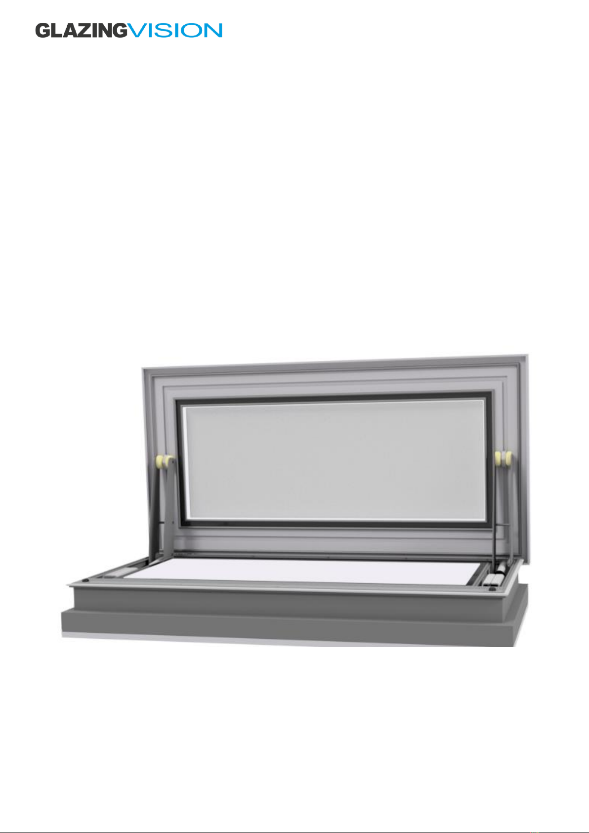
Pairing a Remote Control
Additional remote controls can be paired to or unpaired from the product. To put the product into pairing mode and prepare it for
adding or removing a remote control follow these steps:
1. Ensure that the product is fully closed.
2. Press and hold the CLOSE (down arrow) button on the wall-mounted control switch.
3. Still holding the CLOSE button, press and hold the OPEN (up arrow) button.
4. As soon as the status light starts flashing, release both buttons.
The control switch status light will now flash red and blue alternately for 2 minutes. You now have a 2-minute window in which to
pair the remote to the product.
To Add a Remote
Press any of the buttons on the remote control during the 2-minute pairing window. Wait for approximately 30 seconds and then
press either the open or close buttons (this needs to be done before the 2 minutes are up). The remote control should now be paired
to the product. When using the remote control its status light will illuminate green when the product is in motion.
To Delete a Remote
Ensure there has been at least 2 minutes since either the product was first powered up or from when the pairing procedure was
initiated (i.e. you are not in the 2-minute pairing window). Press all three buttons on the remote control together and immediately
release them. The status light on the remote control should turn red for a few seconds and then turn off. If it turns green or amber,
try pressing the three buttons again. When the red status light turns off, the remote will be unpaired from the product.
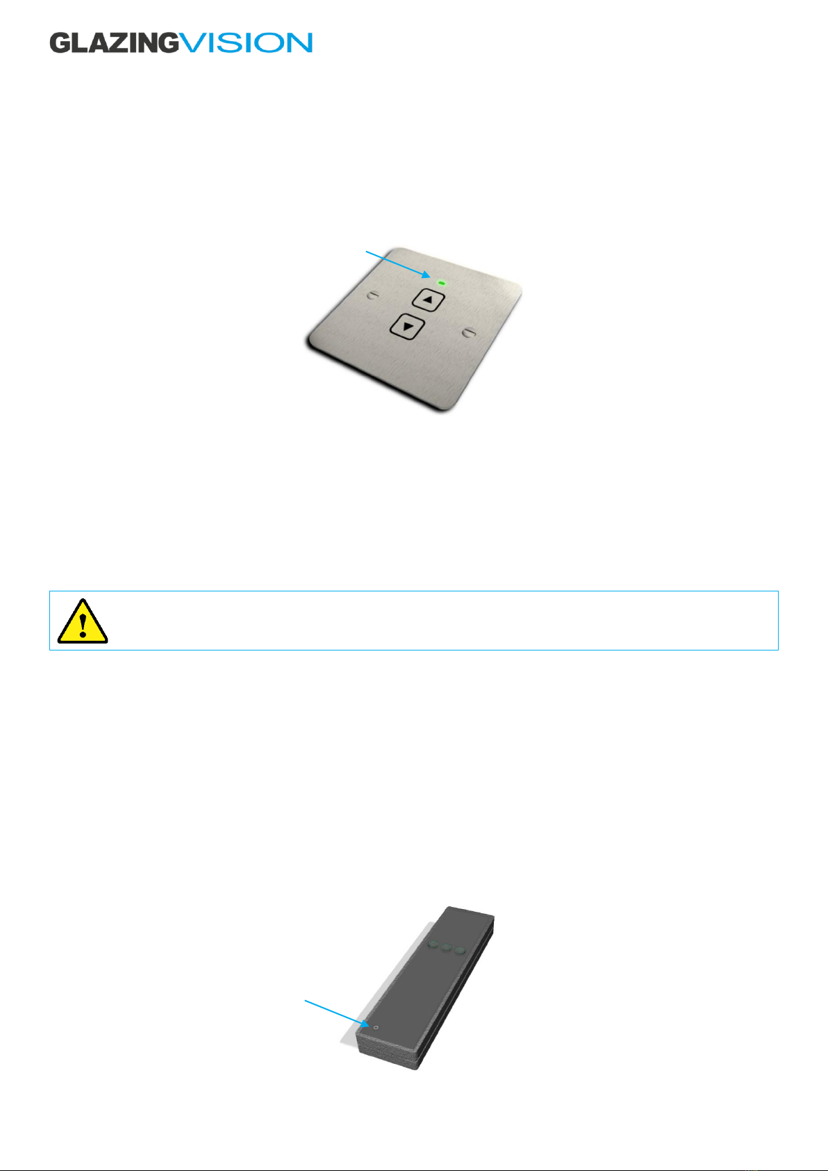
Rain Sensor (Optional)
The rain sensor automatically closes the product when moisture is detected. The status light illuminates green when moisture is
detected and remains green for several minutes. The rain sensor will try to close the product every 60 seconds while the green light
is illuminated. The control switch status light will also flash intermittent green indicating a closure due to rain. The rain sensor is
switched off once the product is completely closed.
The rain sensor should be positioned horizontally (parallel to the ground) in a location that will ensure that it is exposed to the rain
and must be kept clean to function correctly.
Figure 3 –Rain sensor
Rain Sensor Isolation Switch (Optional)
The rain sensor isolation switch is internally mounted and wired directly to the rain sensor cable, allowing the sensor to be switched
on/off. Turning off the switch deactivates the signal from the rain sensor and prevents the product from closing in the event of rain.
This avoids the scenario where someone could be shut outside by the rain sensor when it rains. Ensure that the switch is turned
back on for normal use.
Figure 4 –Rain sensor isolation switch
Status light

406-OM-UK-501 v1.2 –18 Dec 2023
Need assistance? +44 (0)1379 658300 info@glazingvision.co.uk Page 8 of 19
Thermostat (Optional)
The thermostat offers control of the product to regulate the temperature within the building. For security reasons, when the property
is unoccupied, the thermostat should be switched off and the product closed.
External Keypad (Optional)
The keypad option offers secure access into the product from the outside via a numerical pass code. To open or close the product,
enter the four-digit numerical code (Glazing Vision supplies an initial code with the product and instructions for changing it as
required). Unlike the standard internal wall switch, the keypad does not offer ‘press and hold’ operation. The keypad is mounted
remotely.
Figure 5 –External keypad
External Key Switch (Optional)
The key switch option offers the same function as the keypad but via a key operated switch. In addition, the key switch does offer
‘press and hold’ operation. To open the product, turn the key in a clockwise direction. To close the product, turn the key in an anti-
clockwise direction.
Figure 6 –External key switch
Battery Backup (Optional)
The ELMDENE Battery Backup Power Supply is a regulated 27.6V DC output, which is capable of supplying a total of 10 Amps
continuously into the load, whilst also enabling battery charging. The power supply output features electronic short circuit
protection under both mains and standby operation. Two 17Ah batteries (in series to provide 24V DC) allow full operation of the
product for a limited period in the event of a power failure. The battery backup will resume normal operation once mains supply is
restored. Product use should be kept to a minimum during mains failure to maintain battery efficiency.
Figure 7 –Battery backup supply
Building Management System Integration (Optional)
The product can be connected to building management systems. Please contact Glazing Vision for further details if required.

406-OM-UK-501 v1.2 –18 Dec 2023
Need assistance? +44 (0)1379 658300 info@glazingvision.co.uk Page 9 of 19
Product Safety
The Skydoor2 has two infrared photoelectric sensors positioned along the treadplate on the opening end of the product. One sensor
emits a beam which is received by the other during normal operation. If this beam is obstructed by any object, the lid will
immediately stop moving to prevent damage to the framework, mechanisms or object and prevent entrapment. Until the path of
the beam is cleared, the product will not operate. This offers protection against trapping fingers or limbs at the sealing edge.
These sensors do not offer protection against the other edges of the product and only protects along the top of the treadplate. To
avoid serious injury or damage to the product, do not place anything in or near to the product’s mechanisms. Care must always be
taken around motorized equipment. Do not allow unauthorized persons (e.g. children) to operate or play near the product.
Figure 8 –Infrared safety beam sensors

406-OM-UK-501 v1.2 –18 Dec 2023
Need assistance? +44 (0)1379 658300 info@glazingvision.co.uk Page 10 of 19
Recovery of Skydoor2
Initiate product recovery solely in emergency situations, as there may be a need for resetting the product following the completion
of the recovery process.
Before attempting a recover, check that the mains power is present and, if the Rooflight is OPEN, that no obstructions are blocking
the path of the safety sensors (see Fig. 8). Also inspect the GV Control Switch for any LED indications. If there is an issue with the
safety sensors there will be a solid Amber LED. In this case, attempt to electronically override the Product by pressing the override
push button located on the opening inside edge of the base frame (see Fig. 9 & 10 below).
Gently remove the cover cap (see Fig.10) to reveal the override push button, being careful not to damage the internal finishes. To
operate, push the override button and at the same time press the open or close button of the GV Control Switch or Remote Control
(a second person will be required if the control switch is out of reach). If there are no other issues the Amber LED should go out and
the Product will OPEN/CLOSE. If closing the product, ensure you move safely down the stairs inside the building. The override push
button must be held pressed until the product stops. Contact Glazing Vision for further assistance in troubleshooting the safety
sensors.
Figure 9 –Safety sensor override position.
Figure 10 –Safety sensor override
If the product still does not operate, the rooflight can be recovered by using the battery override box provided by Glazing Vision
with your Skydoor2.
Detail on figure 10
Treadplate
Battery override plug
Safety Sensor Override
Cover Cap
Safety sensor

406-OM-UK-501 v1.2 –18 Dec 2023
Need assistance? +44 (0)1379 658300 info@glazingvision.co.uk Page 11 of 19
Battery Override
In case of a power failure and the rooflight is stuck in open position, the rooflight can be closed using the Battery Override Box (see
Fig 11) provided by Glazing Vision. Read the instructions on the box prior to using it.
Figure 11 –Battery Override Box
Gently remove the override plug (see Fig.12) from the base extrusion. Ensure that you can safely close the rooflight and that there
are no people, pets or property left outside.
Figure 12 –Override plug position
Override plug
Connector

406-OM-UK-501 v1.2 –18 Dec 2023
Need assistance? +44 (0)1379 658300 info@glazingvision.co.uk Page 12 of 19
Figure 13 –Override Socket and Connector
Plug the override connector (shown in Fig 13) into the socket inside the extrusion. Beware, once the rooflight is closed, it cannot be
opened.
Due to the loss of power to the unit, there is no safety sensor function. Ensure that no parts of the body or other items will be trapped
by the rooflight lid! Now, press the button on the box and hold it down. You must release the button once the rooflight is closed. If
the mechanisms on both sides of the rooflight are not closing together, stop pressing the button immediately.
Disconnect the connector from the socket and insert the override plug back in the socket.
Once the issue is resolved, the product should be re-initialised.
If the product is stuck in a closed position, contact Glazing Vision to arrange for an engineer to visit and resolve the issue.
Re-Initialisation
If the override has been used, the product may require re-initialising. Once mains power has been restored, re-initialise the product
by pressing close on the control switch. The product is then ready to resume normal service.
If further assistance is required, contact Glazing Vision to arrange for an engineer to visit and resolve the issue.
Socket inside the extrusion
Plug the connector into the socket.
Align the dimple on
the socket and
connector.

406-OM-UK-501 v1.2 –18 Dec 2023
Need assistance? +44 (0)1379 658300 info@glazingvision.co.uk Page 13 of 19
Troubleshooting
The Skydoor2 control board monitors the operation of the product. If a fault is detected, the control board will disable the unit to
prevent possible damage. Fault and standard conditions are indicated by the status light on the control switch (figure 1). The
following table shows the various status light displays and their meanings.
Status Light Shown
Meaning
Continuous green
The product is moving as part of normal operation. If one touch opening/closing has been
activated, the status light will remain lit until the product stops moving.
Intermittent green
(flashes every second)
The product is closing but not under control of the operating switch or remote control e.g. due
to an optional extra (such as a rain sensor) activating. The status light will continue flashing
until the product stops moving.
Intermittent green
(flashes once every 2 seconds)
The fire input connection (if specified) has been triggered. The status light will remain lit when
opening to the fire position and when stationary afterwards so long as the fire input is still
active.
Continuous blue
Indicates that the product has timed out (has taken too long to open/close). This is to avoid
continuous operation of the motor(s) when there is a potential issue. So long as the cause has
been rectified, pressing the open/close button will clear this condition.
Intermittent blue
Indicates an overcurrent or undercurrent condition (the current that the motor(s) are receiving
is outside of the set limits). So long as the cause has been rectified, pressing the open/close
button will clear this condition.
Continuous red
(after power on/fault recovery)
Indicates that the product requires initialisation/synchronisation. Pressing close on the wall
mounted switch will initiate synchronisation of the mechanism(s). The status light will flash red
whilst this is in progress.
Intermittent red
(after power on/fault recovery)
Indicates that the product is initialising/synchronising. The condition will clear automatically
when the product has initialised.
Continuous amber
Indicates that a proximity (safety) sensor has been triggered preventing the product from
closing (it will still open). Once the object(s) obstructing the path of the sensor has been
cleared, normal product operation will be resumed.
Intermittent amber
An unrecoverable fault has been detected by the controller and product operation has been
disabled. This state can be cleared by a button press combination (see table below) or
removing power (including backup batteries) from the product.
If a fault occurs, please refer to the following table. Some faults with the unit may be easily corrected without the need for a site
engineer to visit. Many faults can be cleared by resetting the board. To reset the system, switch off mains power briefly then switch
the power back on again. Most faults should be cleared using this method, however, in the event the fault persists, please contact
Glazing Vision for assistance.
Problem
Possible Cause
Action
Continuous blue
Product has timed out.
The product has taken too long to
open/close.
Check for possible obstructions or parts (e.g.
sensors) that may have been knocked out of
place. Once clear, press the open/close
button.
Intermittent blue
Overcurrent/undercurrent fault.
Something is preventing the
mechanisms from opening/closing.
Check for and remove any obstructions to the
mechanisms. Once clear, press the open/close
button.
The lid is frozen to the base.
Wait until the ice melts before attempting to
operate the product.
The product been left inactive for a
long period (a month or longer).
This fault may occur after a long period of
inactivity, reset the product (turn it off/on
using the mains isolator switch) and try again.
Continuous red
Synchronisation/initialisation state –
the product needs to be initialised.
May occur after turning
off/disconnecting the power when
the mechanisms were not in the
closed position.
Press the close button on the wall mounted
control switch to initiate synchronisation of
the mechanism(s). The status light will flash
red whilst this is in progress.

406-OM-UK-501 v1.2 –18 Dec 2023
Need assistance? +44 (0)1379 658300 info@glazingvision.co.uk Page 14 of 19
Continuous amber
A proximity (safety) sensor has been
triggered –the product will not close.
Something is obstructing the path
of the sensor beams.
Check for and remove any obstructions to the
sensors.
Intermittent amber
Fault lockout state –controller is
unable to reset itself and the product
has been disabled.
Cause unknown.
Do not attempt to recover this fault without
being in full view of the product, ask for
assistance. To force a resynchronisation, press
both the up and down buttons of the wall
mounted control switch at the same time for
two seconds. The control switch status light
will then toggle through red, green and blue
colours, finishing with red. Press the down
button to close the product and initiate
synchronisation (the status light will flash red
whilst this is in progress). If one of the
mechanisms fails to move or if the fault is
triggered for a second time, do not attempt to
try again, and if required refer to the manual
override instructions to close the product.
The product opens or closes for no
apparent reason.
The rain sensor (if specified) is dirty
or still wet triggering the product to
close.
If it is raining wait until the rain stops before
trying to open the product. If the rain sensor
needs cleaning, open the product and isolate
the power supply, then clean the rain sensor.
The thermostat (if specified) is
reacting to a change in temperature
and triggering the product to
operate.
Check that the thermostat is set to the desired
temperature setting.
The BMS system (if specified) is
operating the product remotely.
Check that the BMS system is functioning
correctly.
The rain sensor is not working.
The rain sensor is located in a
position where it is shielded from
the rain or the sensor is dirty.
Check the positioning of the rain sensor and
move it to a more exposed position (a Glazing
Vision engineer may be required for this task).
If the rain sensor needs cleaning, open the
product and isolate the power supply, then
clean the rain sensor.
Glass Specification and Breakage Instructions
Glass Specification
Various options are available at time of order. If specific data is required for the glazing, please contact your supplier for a glass data
sheet covering the specification installed within your unit.
Breakage Instructions
Glass breakage is not covered under the product warranty. In the event of the glass being damaged please contact Glazing Vision
for assistance.

406-OM-UK-501 v1.2 –18 Dec 2023
Need assistance? +44 (0)1379 658300 info@glazingvision.co.uk Page 15 of 19
Routine Testing and Maintenance
General Maintenance and Safety
To keep the Skydoor2 in good working order there are a few basic points that should be observed:
•Do not place anything on, or cause obstruction to the moving section of the product when opening the unit as this may
cause damage to the unit’s mechanisms and/or prevent it from opening.
•Do not walk or sit on the unit (except for the designated treadplate).
•Make sure that fingers and other obstructions are clear of the product and its mechanisms during any operation, severe
damage/injury may be caused.
•Do not touch the motors/mechanisms after operating the unit as they may become hot.
•Do not remove the cover plate protecting the control board, as this may allow the controls to become damaged.
•Do not allow unauthorised persons (e.g. children) to operate the product as this may lead to injury or damage to the
product.
Specific Maintenance Requirements
Maintenance must only be carried out by suitably qualified personnel*. The following maintenance requirements must be
completed and logged on the sheets at the back of this manual. Glazing Vision offers a service/maintenance contract –please
contact us for further details.
*Suitably qualified assumes Glazing Vision Engineers or Approved Installers (installers that have attended a Glazing Vision
installation training course for this product and carry ‘Approved Installer’ status), or an experienced electro-mechanical service
engineer.
Monthly Requirements
•The product should be fully opened and closed to ensure that the seals are free, and the mechanisms function evenly.
•Lubricate (WD-40 Specialist High Performance Silicone Lubricant or equivalent) the hinges.
Annual Requirements (at least annual - recommended every 6 months)
•Check the integrity of the glazing unit (there should not be any misting or condensation).
•Check that all moving parts are free from debris.
•Lubricate (WD-40 Specialist High Performance Silicone Lubricant or equivalent) all moving parts and check they move
freely.
•Check that the mechanisms are straight and true.
•Check that the proximity sensors are clean, aligned, secure and undamaged.
•Check that all fixings are appropriately tightened.
•Check that access to the overrides is clear and advise the relevant party to amend if not.
•Check all electrical cables and ensure that they are not trapped and/or damaged.
•Check that no water is in the unit.
•Clean and inspect all rubber/silicone seals, contact Glazing Vision to arrange for replacement seals to be fitted if required.
•Check that electrical connections are well made and secure.
•Check that the control switch does not show any errors.
•Test the operation.
•Test any optional extras present.
Every 5 Years
•Replace backup batteries (if present).

406-OM-UK-501 v1.2 –18 Dec 2023
Need assistance? +44 (0)1379 658300 info@glazingvision.co.uk Page 16 of 19
Cleaning Requirements
Regular cleaning should be carried out, increasing the frequency if the area is subject to excess debris such as falling leaves or heavy
soiling from atmospheric pollution. Due to the Skydoor2’s unique bonding method and the pitch built into the upstand, there should
be no water ponding on the glass when installed correctly.
Any standard glass cleaning product can be used to clean the glazing unit. However, take care not to use abrasive materials or
cleaners as this may affect the unit and its finish. The framework of the unit can be cleaned using warm soapy water with a soft lint
free cloth. It is important to avoid getting water into the internal channels of the product framework. Therefore, Glazing Vision highly
recommends carrying out any cleaning of the product whilst in the closed position.
•Clear any debris from and around the unit.
•Clean the glass and inspect the integrity of the glazing unit.
•Clean the frame and inspect the finish integrity.
•Clean and inspect all rubber/silicone seals, contact Glazing Vision to arrange for replacement seals to be fitted if required.
•Clean the rain sensor (if present).

406-OM-UK-501 v1.2 –18 Dec 2023
Need assistance? +44 (0)1379 658300 info@glazingvision.co.uk Page 17 of 19
Disposal at End of Life
Glazing Vision design products with ease of recyclability at end of life in mind. Many of the main components used are widely
recyclable and we encourage you to recycle the unit and/or dispose of the component parts responsibly, in accordance with the
guidance from your local authority.
This product comprises the following materials:
Aluminium framework and corner brackets
Widely accepted for recycling at local recycling depots.
Stainless steel
(Fixings, nuts, bolts, screws, brackets etc.)
Widely accepted for recycling at local recycling depots.
Glass
Widely accepted for recycling. Check disposal locations with your local recycling
depot.
PVC/nylon/plastic
Recyclable - check disposal with your local recycling depot.
Rubber seals and silicone sealant
Not currently recyclable.
Electrical components
If your unit is repaired or decommissioned by Glazing Vision, we will remove and
recycle the electrical components under our producer obligations. Alternatively,
please dispose of as Waste Electrical and Electronic Equipment (WEEE) at your
local recycling depot.
Batteries
If your unit is repaired or decommissioned by Glazing Vision, we will remove and
recycle any batteries under our producer obligations. Alternatively, please dispose
of as segregated battery waste at your local recycling depot.
Serial Number
Each Glazing Vision product has a unique serial number. A label giving this serial number is affixed to the exterior of each Skydoor2.
This number should be recorded within the maintenance log section of this manual for future reference. If you need to contact us
for any reason, Glazing Vision may ask for the product’s serial number to enable us to assist with your enquiry.
Warranty Information
A warranty document will be provided with the product. If this is misplaced it can be found at
www.glazingvision.co.uk/resources/warranties. To ensure the warranty is maintained, the product must be regularly
maintained/serviced in accordance with the instructions in this manual.

406-OM-UK-501 v1.2 –18 Dec 2023
Need assistance? +44 (0)1379 658300 info@glazingvision.co.uk Page 18 of 19
Maintenance Log
Project Address: ………………………………………………………………………………………………………………………………….
Unit Serial Number: ……………………………………………………………………………………………………………………………...
Work Completed
Notes
Name
Date
Annual Requirements yes/no
Battery Replacement yes/no
Cleaning Requirements yes/no
Annual Requirements yes/no
Battery Replacement yes/no
Cleaning Requirements yes/no
Annual Requirements yes/no
Battery Replacement yes/no
Cleaning Requirements yes/no
Annual Requirements yes/no
Battery Replacement yes/no
Cleaning Requirements yes/no
Annual Requirements yes/no
Battery Replacement yes/no
Cleaning Requirements yes/no
Annual Requirements yes/no
Battery Replacement yes/no
Cleaning Requirements yes/no
Annual Requirements yes/no
Battery Replacement yes/no
Cleaning Requirements yes/no
Annual Requirements yes/no
Battery Replacement yes/no
Cleaning Requirements yes/no
Annual Requirements yes/no
Battery Replacement yes/no
Cleaning Requirements yes/no
Annual Requirements yes/no
Battery Replacement yes/no
Cleaning Requirements yes/no
Annual Requirements yes/no
Battery Replacement yes/no
Cleaning Requirements yes/no
Annual Requirements yes/no
Battery Replacement yes/no
Cleaning Requirements yes/no
Annual Requirements yes/no
Battery Replacement yes/no
Cleaning Requirements yes/no
Annual Requirements yes/no
Battery Replacement yes/no
Cleaning Requirements yes/no
Annual Requirements yes/no
Battery Replacement yes/no
Cleaning Requirements yes/no

406-OM-UK-501 v1.2 –18 Dec 2023
Need assistance? +44 (0)1379 658300 info@glazingvision.co.uk Page 19 of 19
Work Completed
Notes
Name
Date
Annual Requirements yes/no
Battery Replacement yes/no
Cleaning Requirements yes/no
Annual Requirements yes/no
Battery Replacement yes/no
Cleaning Requirements yes/no
Annual Requirements yes/no
Battery Replacement yes/no
Cleaning Requirements yes/no
Annual Requirements yes/no
Battery Replacement yes/no
Cleaning Requirements yes/no
Annual Requirements yes/no
Battery Replacement yes/no
Cleaning Requirements yes/no
Annual Requirements yes/no
Battery Replacement yes/no
Cleaning Requirements yes/no
Annual Requirements yes/no
Battery Replacement yes/no
Cleaning Requirements yes/no
Annual Requirements yes/no
Battery Replacement yes/no
Cleaning Requirements yes/no
Annual Requirements yes/no
Battery Replacement yes/no
Cleaning Requirements yes/no
Annual Requirements yes/no
Battery Replacement yes/no
Cleaning Requirements yes/no
Annual Requirements yes/no
Battery Replacement yes/no
Cleaning Requirements yes/no
Annual Requirements yes/no
Battery Replacement yes/no
Cleaning Requirements yes/no
Annual Requirements yes/no
Battery Replacement yes/no
Cleaning Requirements yes/no
Annual Requirements yes/no
Battery Replacement yes/no
Cleaning Requirements yes/no
Annual Requirements yes/no
Battery Replacement yes/no
Cleaning Requirements yes/no
Annual Requirements yes/no
Battery Replacement yes/no
Cleaning Requirements yes/no
Annual Requirements yes/no
Battery Replacement yes/no
Cleaning Requirements yes/no
Table of contents
Other GLAZING VISION Indoor Furnishing manuals

GLAZING VISION
GLAZING VISION Ridgeglaze User manual

GLAZING VISION
GLAZING VISION GV Standard Pyramid Service manual

GLAZING VISION
GLAZING VISION GV Standard Kerb Manual

GLAZING VISION
GLAZING VISION Pitchridge User manual

GLAZING VISION
GLAZING VISION Pitchvent User manual

GLAZING VISION
GLAZING VISION Free Standing Skybox User manual
Popular Indoor Furnishing manuals by other brands

Home Decorators Collection
Home Decorators Collection MARTHA STEWART WSMSL-V8CDW Assembly instructions

Habitat
Habitat Kott 811664 quick start guide

Claire Deco
Claire Deco TEKNO 40 installation instructions

OLG
OLG EkoSystem Assembly instructions

Acme Furniture
Acme Furniture Yuri 81195 Assembly instructions

WB Mfg
WB Mfg EPIC EP3082-FXO-RR6 Assembly instructions