GLI Internationa D53 Instruction Manual

Rev. 0-599 Model D53 D.O. Analyzer (universal-mount 1/2 DIN)
1
OPERATING INSTRUCTION MANUAL
Model D53
Dissolved Oxygen Analyzer
(Universal-mount 1/2 DIN style;
user-selectable D.O. concentration
displayed in ppm, mg/l, or % saturation)
Worldwide Sales:
GLI International, Inc.
9020 West Dean Road
Milwaukee, Wisconsin 53224, U.S.A.
phone: [414] 355-3601
fax: [414] 355-8346
e-mail: info@gliint.com
European Sales:
GLI International Ltd
Ivel Road, Shefford
Bedfordshire. SG17 5JU England
phone: 01462 817070
fax: 01462 813680
e-mail: gli@gli.co.uk
In the interest of improving and updating its equipment, GLI reserves the right to alter specifications to equipment at any time.
A Viridor Instrumentation company

Model D53 D.O. (universal-mount 1/2 DIN) Rev. 0-599
2

Rev. 0-599 Model D53 D.O. Analyzer (universal-mount 1/2 DIN)
3
IMPORTANT SAFETY INFORMATION
This analyzer is compliant with safety standards as outlined in:
FMRC Class Numbers 3600, 3611, and 3810 (U.S.A.)
CSA C22.2 No. 142 and C22.2 No. 213 (Canada)
EN 61010-1 (European Community)
Please read and observe the following:
•Opening the analyzer door exposes you to line power voltage, if present, at terminals on TB2 and TB3
inside the enclosure. This may be hazardous. Always remove line power before entering this area in
the analyzer. However, the analyzer door assembly contains only low voltage and is completely safe
to handle.
•Wiring or repairs should only be performed by qualified personnel and only to an unpowered analyzer.
•Whenever it appears that analyzer safety is questionable, disable the analyzer to ensure against any
unintended operation. For example, an unsafe condition is likely when:
1) The analyzer appears visibly damaged.
2) The analyzer fails to operate properly or provide the intended measurements.
3) The analyzer has been stored for long periods at temperatures above 158°F (70°C).
•This analyzer must be installed by specially trained personnel in accordance with relevant local codes
and instructions contained in this operating instruction manual. Observe the analyzer’s technical
specifications and input ratings. If one line of the line power mains is not neutral, use a double-pole
mains switch to disconnect the analyzer.
HELPFUL IDENTIFIERS
In addition to information on installation and operation, this instruction manual may contain
WARNINGS pertaining to user safety, CAUTIONS regarding possible instrument malfunction, and
NOTES on important, useful operating guidelines.
WARNING:
A WARNING LOOKS LIKE THIS. IT WARNS YOU OF THE POTENTIAL
FOR PERSONAL INJURY.
CAUTION:
A CAUTION LOOKS LIKE THIS. IT ALERTS YOU TO POSSIBLE
INSTRUMENT MALFUNCTION OR DAMAGE.
☞NOTE: A note looks like this. It alerts you to important, useful operating
information.

Model D53 D.O. (universal-mount 1/2 DIN) Rev. 0-599
4
Definition of Equipment Symbols
This symbol means CAUTION and alerts you to possible danger or
instrument malfunction. Refer to this manual before proceeding.
This symbol means that this is a protective ground terminal and
alerts you to connect an earth ground to it.
This symbol means that there is alternating current present and
alerts you to be careful.
WARRANTY
GLI International, Inc. warrants the Model D53 to be free from defects in material
or workmanship for a period of 2 years (24 months) from the date of shipment of
this product from our facility. A warranty claim will not be honored if defects are
not reported within the warranty period, or if GLI International determines that
defects or damages are due to normal wear, misapplication, lack of mainte-
nance, abuse, improper installation, alteration, or abnormal conditions. GLI
International’s obligation under this warranty shall be limited to, at its option, re-
placement or repair of this product. The product must be returned to GLI
International, freight prepaid, for examination. The product must be thoroughly
cleaned and any process chemicals removed before it will be accepted for re-
placement or repair. GLI International’s liability shall not exceed the cost of the
product. Under no circumstances will GLI International be liable for any inciden-
tal or consequential damages, whether to person or property. GLI International
will not be liable for any other loss, damage or expense of any kind, including
loss of profits, resulting from the installation, use, or inability to use this product.

Rev. 0-599 Model D53 D.O. Analyzer (universal-mount 1/2 DIN)
5
CONDENSED OPERATING INSTRUCTIONS
This manual contains details for all operating aspects of the instrument. The following condensed in-
structions are provided to assist you in getting the instrument started up and operating as quickly as
possible. These condensed instructions only pertain to basic dissolved oxygen measurement op-
eration (in ppm). To use specific features of the instrument, refer to the appropriate sections in this
manual for instructions.
A. CONNECTING SENSOR(S)
The analyzer can always be used with one sensor connected to SENSOR A terminals. When the
analyzer is equipped with the optional two sensor input software, a second sensor can be connected
to SENSOR B terminals and used for monitoring.
1. After the analyzer is properly mounted (Part Two, Section 2), install the GLI membrane dissolved
oxygen sensor(s). Refer to the sensor instruction manual for details.
2. When using GLI mounting hardware, plug the sensor cable into the mating receptacle on the
junction box. Route the 6-conductor interconnect cable (GLI part number 1W1100) from the
junction box to the analyzer.
3. At the analyzer end of the interconnect cable, twist the two shield wires together. Then insulate
them with plastic tubing or tape to prevent inadvertent shorting, and connect the combined shield
to one of the 5 open holes on the grounding strip at the bottom of the analyzer case (Figure 2-3).
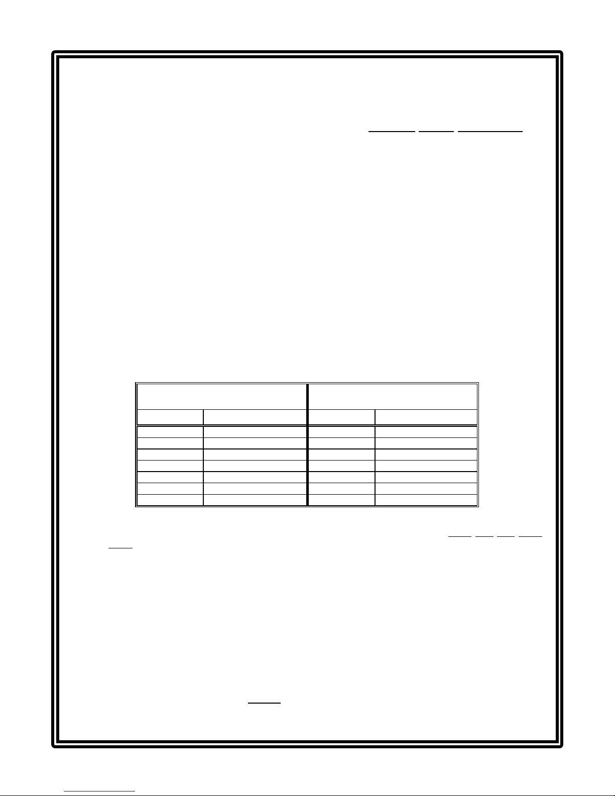
4. Connect the other interconnect cable wires to the analyzer SENSOR A terminals on TB1,
matching colors as indicated:
Sensor A
Interconnect Cable Connections Optional Sensor B Input
Interconnect Cable Connections
Wire Colors At Analyzer Terminals Wire Colors At Analyzer Terminals
Red #10 on TB1 Red #16 on TB1
Green #11 on TB1 Green #17 on TB1
Blue #12 on TB1 Blue #18 on TB1
White #13 on TB1 White #19 on TB1
Black #14 on TB1 Black #20 on TB1
Yellow #15 on TB1 Yellow #21 on TB1
Cable shields Grounding strip lug Cable shields Grounding strip lug
5. At the junction box end of the interconnect cable, twist the two shield wires together. Then con-
nect the combined shield to the junction box terminal corresponding to the white wire with black
stripe. Connect the other interconnect cable wires to terminals corresponding to their wire colors.
NOTE: When the analyzer is equipped with the optional sensor quick-disconnect receptacle(s),
simply plug the sensor cable(s) into them. This eliminates using the junction box supplied
with GLI sensor mounting hardware, and the need for interconnect cable.
B. CONFIGURING SENSOR TEMPERATURE ELEMENT(S)
The analyzer is supplied factory-set for automatic temperature compensation using the NTC 30K
ohm thermistor element built into GLI membrane dissolved oxygen sensors. For fixed manual tem-
perature compensation, you must change the temperature element type to “MANUAL” (see Part
Three, Section 4.3, subheading “Selecting Temperature Element Type”) and enter a temperature.
NOTE: When the analyzer is equipped with the optional two sensor input software and only one
sensor is being used, the unused sensor input must be set for “MANUAL” compensation to
prevent a “WARNING: CHECK STATUS” message from appearing.
(continued on next page)

Model D53 D.O. (universal-mount 1/2 DIN) Rev. 0-599
6
CONDENSED OPERATING INSTRUCTIONS
C. CONNECTING LINE POWER
Important: Follow the instructions in Part Two, Section 3.5 to connect line power to the analyzer.
D. ADJUSTING DISPLAY CONTRAST
Ambient lighting conditions may make it necessary to adjust display contrast to improve visibility.
With the MEASURE screen displayed, press and hold the ENTER key and simultaneously press the
ññ or òò key until attaining the desired contrast.
E. CALIBRATING THE ANALYZER
The analyzer must be calibrated for dissolved oxygen concentration so that measured values will
correspond to actual process values. Use one of the three different methods available.
Calibration Tip! It is highly recommended to use the “AIR CAL” method with one of the special
calibration bags provided with the GLI membrane D.O. sensor because this:
•Ensures high calibration accuracy by providing a stable atmosphere at the sensor membrane.
•Provides more convenience than using a portable meter to determine the known D.O. value
(even when an optional GLI washer head assembly is attached to sensor for self-cleaning).
•Provides high repeatability because the sensor is in a controlled environment.
CAUTION:
DURING INTIAL STARTUP AND BEFORE CALIBRATION, ALWAYS CONDITION THE
MEMBRANE D.O. SENSOR BY OPERATING IT IN WATER FOR AT LEAST 12 HOURS TO
POLARIZE THE ELECTRODES. FAILURE TO PROPERLY CONDITION THE SENSOR WILL
RESULT IN SIGNIFICANT MEASUREMENT ERROR.
NOTE: When using a second sensor, calibrate SENSOR B in the same way using its respective
menu screens.
Since GLI highly recommends the “AIR CAL” method for calibration, it is described below. (To use
one of the other methods, refer to Part Three, Section 5 for instructions.) With the “AIR CAL”
method, the analyzer automatically calibrates itself using the atmospheric pressure or altitude value
you previously entered, and the measured temperature in the calibration bag. (For theoretical D.O.
calibration values based on measured temperature, refer to Table D. The actual calibration value
may be slightly different because of the variation for the entered atmospheric pressure or altitude.)
1. Enter the known atmospheric pressure or altitude in your geographic area.
A. Press MENU key to display
CONFIGURE
TEST/MAINT
EXIT
.
(continued on next page)

Rev. 0-599 Model D53 D.O. Analyzer (universal-mount 1/2 DIN)
7
CONDENSED OPERATING INSTRUCTIONS
E. CALIBRATING THE ANALYZER -- (continued)
B. Use òò key to select “CONFIGURE” line, and press ENTER key to display .
C. Use òò key to select “PRESSURE UNITS” line, and press ENTER key to display .
Use òò and ññ keys to select the desired units (pressure in mm of mercury or altitude in feet
or meters), and press ENTER key.
D. With the screen displayed, use òò key to select the “SENSOR” or
“SENSOR A” line and press ENTER key to display:
E. Use òò key to select the “SET PRESSURE” or “SET ALTITUDE” line, and press ENTER key
to display or . Adjust the displayed value to the known
pressure or altitude, and press ENTER key to enter the value. (Use ïï and ðð keys for
coarse adjust; ññ and òò keys for fine adjust.)
Calibration Tip! If at any time during calibration, the “CONFIRM FAILURE?” screen appears,
press ENTER key to confirm. Then, use the ññ or òò key to select between “CAL REPEAT?” or
“CAL EXIT?” and do one of the following:
•With the “CAL REPEAT?” screen selected, press ENTER key to repeat calibration.
•With the “CAL: EXIT?” screen selected, press ENTER key. Then, after the “CONFIRM
ACTIVE?” screen appears, press ENTER key to return the analog outputs and relays to their
active states (MEASURE screen appears).
2. Press MENU key to display
CONFIGURE
TEST/MAINT
EXIT
.
(continued on next page)

Model D53 D.O. (universal-mount 1/2 DIN) Rev. 0-599
8
CONDENSED OPERATING INSTRUCTIONS
E. CALIBRATING THE ANALYZER -- (continued)
3. With the “CALIBRATE” line selected, press ENTER key to display .
4. With the “SENSOR” or “SENSOR A” line selected, press ENTER key to display .
5. Use òò key to select the “AIR CAL” line, and press ENTER key to display .
6. Press ENTER key to “hold” the analog outputs and relays at their present states during zeroing.
(Outputs can also be transferred to present values or allowed to remain active.)
7. Remove the sensor from the conditioning water, place the provided special calibration bag over
the wet membrane end of the sensor, and secure the bag to the sensor body.
8. With the screen displayed and the sensor held in air, press ENTER key to
start the automatic calibration (“AIR CAL PLEASE WAIT” screen appears for a few minutes ena-
bling the D.O. and temperature signals to stabilize).
9. After the “AIR CAL: CONFIRM CAL OK?” screen appears, press ENTER key to end calibration.
10. After the “CONFIRM ACTIVE?” screen appears showing the active measurement reading, re-
move the calibration bag from the sensor, and place the sensor into the process. When the
reading corresponds to the actual typical process value, press ENTER key to return the analog
outputs and relays to their active states (MEASURE screen appears).
This completes GLI’s “AIR CAL” calibration. The analyzer is now ready to accurately measure dis-
solved oxygen concentration in ppm.
To change the display units on the MEASURE screen, for example, from ppm to mg/l or % satura-
tion, refer to Part Three, Section 4.3 under the subheading “Selecting Measurement Display Format.”
F. COMPLETING ANALYZER CONFIGURATION
To further configure the analyzer to your application requirements, use the appropriate CONFIGURE
screens to make selections and “key in” values. Refer to Part Three, Section 4 for complete configu-
ration details.

Rev. 0-599 Model D53 D.O. Analyzer (universal-mount 1/2 DIN)
9
TABLE OF CONTENTS
PART ONE - INTRODUCTION
SECTION 1 GENERAL INFORMATION
1.1 Capability Highlights........................................................15-17
1.2 Modular Construction............................................................17
1.3 Retained Configuration Values.............................................17
1.4 Analyzer Serial Number........................................................17
1.5 EMI/RFI Immunity ................................................................. 18
SECTION 2 SPECIFICATIONS ...................................................................19-20
PART TWO - INSTALLATION
SECTION 1 UNPACKING.................................................................................21
SECTION 2 MECHANICAL REQUIREMENTS
2.1 Location................................................................................21
2.2 Mounting..........................................................................21-23
2.3 Conduit Hole Requirements.................................................. 23
SECTION 3ELECTRICAL CONNECTIONS
3.1 GLI Membrane Dissolved Oxygen Sensor(s)...................24-26
3.2 Analog Outputs..................................................................... 27
3.3 Relay Outputs....................................................................... 28
3.4 Closed Contact TTL Input.....................................................29
3.5 Line Power.......................................................................29-30
PART THREE - OPERATION
SECTION 1 USER INTERFACE
1.1 Display.............................................................................31-32
1.2 Keypad.............................................................................32-33
1.3 MEASURE Screen (normal display mode)............................34
SECTION 2 MENU STRUCTURE
2.1 Displaying Main Branch Selection Screen............................35
2.2 Displaying Top-level Menu Screens................................35-36
2.3 Displaying Submenu Screens...............................................36
2.4 Adjusting Edit/Selection Screen Values................................ 36
2.5 Entering (Storing) Edit/Selection Screen Values/Choices....36
SECTION 3 ADJUSTING DISPLAY CONTRAST............................................37

Model D53 D.O. (universal-mount 1/2 DIN) Rev. 0-599
10
TABLE OF CONTENTS (continued)
SECTION 4 CONFIGURING THE ANALYZER
4.1 Selecting Language to Operate Analyzer.............................37
4.2 Configuring Units for Application Conditions:
Selecting Atmospheric Pressure Units
(mmHg, altitude in ft., or altitude in m).......................38
Selecting Salinity Units (mS/cm or milliMol/l) .................. 38
4.3 Configuring Sensor (A and B) Characteristics:
Selecting Measurement Display Format
(ppm, mg/l, % saturation)...........................................39
Setting Sensor Signal Filter Time....................................40
Setting Atmospheric Pressure Value...............................40
Setting Salinity Value (for process or clean water).......... 41
Selecting Pulse Suppression (on/off)..............................41
Changing Top Line Notation on MEASURE Screen...........42
Selecting Temperature Element Type........................42-43
4.4 Selecting Temperature Display Format (°C or °F)................ 43
4.5 Configuring Outputs (1 and 2):
Assigning Representative Parameter.........................44-45
Setting Parameter Values for 0/4 and 20 mA.............45-46
Setting Transfer Value (mA)............................................46
Setting Output Filter Time ...............................................47
Setting Output Scale Low Endpoint (0/4 mA)..................47
4.6 Configuring Relays (A, B, C, and D):
Assigning Representative Parameter.........................48-49
Selecting Function Mode (alarm, control,
status, or timer).....................................................49-50
Selecting Transfer Mode (relay on or off)........................51
Setting Activation (Configuration) Values...................51-53
4.7 Enabling/Disabling Passcode..........................................53-54
4.8 Summary of Configuration Settings
(Ranges/Choices and Defaults).......................................55-57
SECTION 5 CALIBRATING THE ANALYZER
5.1 Things to Know About D.O. Calibration................................ 58
5.2 D.O. Calibration:
SAMPLE CAL Method ................................................60-62
AIR CAL Method (highly recommended)....................62-64
SATURATION CAL Method........................................64-65
5.3 Temperature Calibration:
1 POINT SAMPLE Method .........................................66-67
2 POINT SAMPLE Method .........................................67-69
5.4 Analog Outputs (1 and 2) Calibration ..............................70-71

Rev. 0-599 Model D53 D.O. Analyzer (universal-mount 1/2 DIN)
11
TABLE OF CONTENTS (continued)
SECTION 6 TEST/MAINTENANCE
6.1 Checking Analyzer, Sensor, and Relay Status...............72-73
6.2 Holding Outputs................................................................... 74
6.3 Resetting Overfeed Timers..................................................74
6.4 Providing Output (1 and 2) Test Signals .............................75
6.5 Testing Relay (A, B, C, and D) Operation ...........................75
6.6 Checking EPROM Version ..................................................76
6.7 Selecting Type of Simulated Value...................................... 76
6.8 Setting Simulation Value .....................................................77
6.9 Resetting Configuration Values to Factory Defaults.......77-78
6.10 Resetting Calibration Values to Factory Defaults................78
SECTION 7 RELAY OVERFEED TIMER FEATURE
7.1 Why Use an Overfeed Timer............................................... 79
7.2 Configuring Relay Overfeed Timers....................................79
7.3 Overfeed Timer “Timeout” Operation ..................................79
7.4 Resetting Overfeed Timers..................................................79
7.5 Interactions with Other Analyzer Functions....................79-80
SECTION 8 HART OPTION
8.1 Introduction.......................................................................... 81
8.2 Analyzer Operating Modes for HART Network...............82-83
8.3 SINGLE MODE (Point-to-Point) Wiring Arrangement .........83
8.4 MULTI-DROP Wiring Arrangement.....................................84
8.5 HART Preferences Setup:
Changing Polling Address.............................................. 85
Viewing Number of Required Preambles ..................85-86
8.6 Device Preferences Setup:
Viewing Final Assembly Number....................................86
Viewing Model Number.............................................86-87
Viewing Manufacturer.....................................................87
Assigning a Tag .............................................................87
Assigning a Descriptor...................................................88
Assigning a Message..................................................... 88
Assigning User-defined Date ....................................88-89
Viewing Identification (ID) .............................................. 89
Viewing Revisions..........................................................89
8.7 “Master Reset” Function......................................................90
8.8 “Refresh” Function............................................................... 90
8.9 Protocol Command Set for PC Programming......................90

Model D53 D.O. (universal-mount 1/2 DIN) Rev. 0-599
12
TABLE OF CONTENTS (continued)
PART FOUR - SERVICE AND MAINTENANCE
SECTION 1 GENERAL INFORMATION
1.1 Inspecting Sensor Cable(s) ..................................................91
1.2 Replacing Fuse(s)................................................................. 91
1.3 Replacing Relays..................................................................91
SECTION 2 PRESERVING MEASUREMENT ACCURACY
2.1 Keeping Sensor(s) Clean......................................................92
2.2 Keeping Analyzer Calibrated................................................92
2.3 Avoiding Electrical Interference............................................ 92
SECTION 3 TROUBLESHOOTING
3.1 Ground Loops:
Determining if Ground Loop Exists..................................93
Finding Source of Ground Loop......................................94
3.2 Isolating Measuring System Problem:
Checking Electrical Connections.....................................94
Verifying Sensor Operation.............................................94
Verifying Analyzer Operation......................................94-95
Verifying Interconnect Cable Integrity .............................95
SECTION 4 ANALYZER REPAIR/RETURN
4.1 Customer Assistance............................................................ 96
4.2 Repair/Return Policy.............................................................96
PART FIVE - SPARE PARTS AND ACCESSORIES
......................................................................................................97

Rev. 0-599 Model D53 D.O. Analyzer (universal-mount 1/2 DIN)
13
TABLE OF CONTENTS (continued)
ILLUSTRATIONS
Figure 1-1 EMI/RFI Immunity Diagram ........................................................................................18
Figure 2-1 Analyzer Mounting Arrangements..............................................................................22
Figure 2-2 Analyzer Installation Dimension Details .....................................................................23
Figure 2-3 Analyzer Terminal Block Designations.......................................................................25
Figure 2-4 Connecting GLI Membrane Dissolved Oxygen Sensor(s)..........................................26
Figure 2-5 Connecting Control/Alarm Device(s) to Electromechanical Relay(s)..........................28
Figure 2-6 Connecting 115 Volt Single Phase Line Power (90-130 VAC)...................................30
Figure 2-7 Connecting 230 Volt Single Phase Line Power (180-260 VAC).................................30
Figure 2-8 Connecting 230 Volt Split Phase Line Power (180-260 VAC)....................................30
Figure 3-1 Analyzer Keypad........................................................................................................32
Figure 3-2 Location of Analyzer SINGLE MODE/MULTI-DROP Switch.......................................83
Figure 3-3 HART SINGLE MODE (Point-to-Point) Wiring Arrangement (for single analyzer)......83
Figure 3-4 HART MULTI-DROP Wiring Arrangement (for multiple analyzers).............................84
TABLES
Table A Relay Configuration Settings.................................................................................51-52
Table B Analyzer Configuration Settings (Ranges/Choices and Defaults).........................55-57
Table C Comparison of Calibration Methods...........................................................................59
Table D Temperature versus Water-saturated Concentration of Oxygen................................62
Table E Relay Overfeed Timer Interactions with Other Analyzer Functions............................80

Model D53 D.O. (universal-mount 1/2 DIN) Rev. 0-599
14

PART ONE - INTRODUCTION SECTION 1 - GENERAL INFORMATION
Rev. 0-599 Model D53 D.O. Analyzer (universal-mount 1/2 DIN)
15
PART ONE - INTRODUCTION
SECTION 1
1.1 Capability Highlights
Sensor Input
MEASURE Screen
(normal display mode)
Passcode-protected
Access
Calibration Guidelines
The analyzer always has one sensor input but may be
equipped with the optional two sensor input software. This
option provides two independent sensor inputs for monitor-
ing two measurement points. Each input accepts a GLI
membrane dissolved oxygen sensor that has a built-in NTC
30K ohm thermistor.
The measured dissolved oxygen is shown on the
MEASURE screen (normal display mode). When the ana-
lyzer is equipped with the optional two sensor input
software, pressing the ðð or ïï key while viewing the
MEASURE screen sequentially shows these measurements:
•Measured Sensor A dissolved oxygen.
•Measured Sensor B dissolved oxygen.
•Measured Sensor A and B dissolved oxygen and
temperatures (all together on same screen).
The bottom auxiliary display line, shown in reverse video,
can be changed by pressing the òò and ññ keys to show
these other measurements:
•Measured Sensor A temperature (°C or °F).
•Measured Sensor B temperature (°C or °F).
•Analog Output #1 value (mA).
•Analog Output #2 value (mA).
For security, you can enable a passcode feature to restrict
access to configuration and calibration settings to author-
ized personnel only. See Part Three, Section 4.7 for details.
Three methods are provided for D.O. calibration. It is highly
recommended to use the “AIR CAL” method for conven-
ience and accuracy. For calibration details on all methods,
refer to Part Three, Sections 5.1 and 5.2. The analyzer also
provides two methods for calibrating temperature (Section
5.3). This feature, however, is typically not needed since the
analyzer is factory-calibrated for highly accurate tempera-
GENERAL INFORMATION

PART ONE - INTRODUCTION SECTION 1 - GENERAL INFORMATION
Model D53 D.O. (universal-mount 1/2 DIN) Rev. 0-599
16
ture measurement. The mA
values for each analog output
can also be calibrated (Sec-
tion 5.4).
Analog Outputs
☞
Relays
☞

PART ONE - INTRODUCTION SECTION 1 - GENERAL INFORMATION
Rev. 0-599 Model D53 D.O. Analyzer (universal-mount 1/2 DIN)
17
The analyzer provides two
isolated analog outputs (#1
and #2). Each output can be
set to be 0-20 mA or 4-20
mA, and assigned to repre-
sent the measured dissolved
oxygen or temperature.
NOTE: When the analyzer
is equipped with the
optional two sensor
input software, an
analog output can
also represent the
SENSOR B meas-
ured dissolved
oxygen or tem-
perature.
Parameter values can be
entered to define the end-
points at which the minimum
and maximum analog output
values are desired.
During calibration, both ana-
log outputs can be selected
to:
•Hold their present values
(HOLD OUTPUTS)
•Transfer to preset values
to operate control ele-
ments by an amount
corresponding to those
values (XFER
OUTPUTS)
•Remain active to respond
to the measured value
(ACTIVE OUTPUTS).
For analog output transfer
setup details, see Part Three,
Section 4.5 under the sub-
heading “Setting Transfer
Value.”
The analyzer has four electromechanical relays, all with
SPDT contacts. Each relay can be set to function as a con-
trol relay, dual-alarm relay, status relay, or a timer relay,
and assigned to be driven by the measured dissolved oxy-
gen or temperature.
NOTE: When the analyzer is equipped with the optional
two sensor input software, a relay can also repre-
sent the SENSOR B measured dissolved oxygen
or temperature.
Since timer and status function relays are driven by
other criteria, the parameter assigned to these re-
lays is not relevant and, therefore, disregarded.
Refer to Part Three, Section 4.6 for relay setup details.

PART ONE - INTRODUCTION SECTION 1 - GENERAL INFORMATION
Model D53 D.O. (universal-mount 1/2 DIN) Rev. 0-599
18
☞
1.2 Modular Construction
1.3 Retained
Configuration Values
1.4 Analyzer
Serial Number
NOTE: When a relay is set to function as a status relay, it is
no longer configurable. Instead, it becomes a dedi-
cated system diagnostic-only alarm relay that
automatically energizes when the “WARNING
CHECK STATUS” message flashes on the
MEASURE screen. This occurs when the analyzer
detects a “fail” diagnostic condition. See Part Three,
Section 6.1 for more details.
Except for status relays, during calibration the relay on/off
states are affected in the same way as the analog outputs
by the “(HOLD/XFER/ACTIVE OUTPUTS)” screen selec-
tion. These relays are also held at their present on/off
states, transferred to desired preset on/off states, or remain
active to respond to measured values. For relay transfer
setup details, see Part Three, Section 4.6, under the sub-
heading “Selecting Transfer Mode.”
The modular construction of the analyzer simplifies field
servicing and provides electrical safety. The front door/
keypad assembly uses voltages no greater than 24 VDC,
and is completely safe to handle.
Opening the analyzer door accesses terminals inside the
enclosure for electrical connections. Line power must be
connected to specifically designated terminals on TB3.
WARNING:
REMOVE LINE POWER BEFORE NEARING THIS AREA
TO AVOID ELECTRICAL SHOCK.
All user-entered configuration values are retained indefi-
nitely, even if power is lost or turned off. The non-volatile
analyzer memory does not require battery backup.
A label with the analyzer model number, serial number,
build date, and other items is affixed to the top of the enclo-
sure.

PART ONE - INTRODUCTION SECTION 1 - GENERAL INFORMATION
Rev. 0-599 Model D53 D.O. Analyzer (universal-mount 1/2 DIN)
19
1.5 EMI/RFI Immunity The analyzer is designed to provide protection from most
normally encountered electromagnetic interference. This
protection exceeds US standards and meets European
IEC 801-series testing for electromagnetic and radio fre-
quency emissions and susceptibility. Refer to Figure 1-1
and the specifications in Section 2.1 for more information.
FIGURE 1-1 EMI/RFI Immunity Diagram

PART ONE - INTRODUCTION SECTION 2 - SPECIFICATIONS
Model D53 D.O. (universal-mount 1/2 DIN) Rev. 0-599
20
SECTION 2
2.1 Operational Display....................................... Graphic dot matrix LCD, 128 x 64 pixels with
LED backlighting; 1/2 inch (13 mm) main
character height; 1/8 inch (3 mm) auxiliary
information character height; menu screens
contain up to six text lines
Measurement Ranges
Dissolved Oxygen................. 0-99.99 ppm, 0-99.99 mg/l, or 0-999.9 % sat.
Temperature......................... 32.0-212.0°F or 0.0-100.0°C
mA Outputs (#1 and #2)........ 0.00-20.00 mA or 4.00-20.00 mA
Ambient Conditions:
Operation.............................. -4 to +140°F (-20 to +60°C); 0-95% relative
humidity, non-condensing
Storage................................. -22 to +158°F (-30 to +70°C); 0-95% relative
humidity, non-condensing
Relays: Types/Outputs.................Four electromechanical relays; SPDT (Form C)
contacts; U.L. rated 5A 115/230 VAC, 5A @ 30
VDC resistive
Operational Mode............Each relay (A, B, C, and D) can be assigned to
be driven by:
•Sensor A dissolved oxygen
•Sensor A temperature
•Sensor B dissolved oxygen
•Sensor B temperature
Function Modes:
Control.................... Settings for high/low phasing, setpoint, dead-
band, overfeed timer, off delay, and on delay
Alarm.........................Settings for low alarm point, low alarm point
deadband, high alarm point, high alarm point
deadband, off delay, and on delay
Status.........................Not configurable; relay only activates when a
sensor or analyzer “fail” diagnostic WARNING
condition exists
Timer..........................Relay is activated by user-entered interval and
time duration values to control a sensor cleaning
system such as a GLI air blast cleaning system
Indicators.........................Relay A, B, C, and D annunciators indicate
respective relay status
Temperature Compensation....... Automatic from 32.0 to 122.0°F (0.0-50.0°C),
or manually fixed at a user-entered temperature
Sensor-to-Analyzer Distance...... 1000 ft. (305 m) maximum
Power Requirements.................. 90-130 VAC, 50/60 Hz. (10 VA max.) or
180-260 VAC, 50/60 Hz. (10 VA max.)
D.O. Calibration Methods:
SAMPLE CAL......................... Enter one sample value derived by laboratory
analysis or a comparison reading.
AIR CAL................................. For use only when the sensor is calibrated in
air. The analyzer computes and displays the
ppm value based on the entered atmospheric
pressure or altitude, and the temperature of
the 100% saturated air.
SPECIFICATIONS
only with optional
two sensor input
software
}
Table of contents