Global Contract Diet User manual

Installation Manual 2017
Visit us on the Internet at globalcontract.com • (416) 739-5000
ISO 9001:2015OHSAS 18001:2007 ISO 14001:2015 Global Contract Inc. 565 Petrolia Road
North York, Ontario, M3J 2X8
REVISED: FALL 2017

Page • globalcontract.com2
• Summer 2017
GLOBALContract
TABLE OF CONTENTS
Panel Connector
Off Module panel Connector
Wall Adapter
Diet to Boulevard Slot Connector
Diet to Boulevard Connecting Kit
Diet Freestanding Panel Mobile Kit
Diet Panel Gap Filler Installation
90 Degree Configurations
Worksurface Support
Worksurface Universal Flat Bracket
Gable Leg
Pedestal Bracket / Corner Plate
Transaction Bracket
Combining Diet and Boulevard Worksurfaces
Off-Module Cantilever
Storage
Open Shelf
Off - Module Shelf
DSADA Easy-Up Diet Overhead
Diet Electrical
Diet Electrical Components
Diet Electrical Installation
Diet Communication Installation
Cable management
3
4
5
6
8
9
10
11
20
21
22
23
24
25
26
27
28
29
30
12
13
14
16
18
Panels
Worksurfaces
Storage
Electrical
P.03
P.20
P.27
P.12
NOTE: Any alterations to listed components will void the manufacturer’s warranty.
The manufacturer will not be responsible for any damage or bodily harm caused
by alterations in accordance with national or local electrical codes and manufac-
turer’s specifications. In accordance with the manufacturer’s policy of continual
product improvement, the product presented in this document is subject to
change without notice or obligation.24
Please contact your Global Contract Service Representative at 416-739-5000 for
any questions or concerns.

•Pageglobalcontract.com 3
• Summer 2017
GLOBALContract
INSTALLATION GUIDELINES
Panel Connector
Every panel ships with a connecting kit comprising hinges, spacers, screws and hinge
pins. Not all pieces included in the connecting kit might get used with every panel (con-
necting two stand alone panels at 90°, for example, will only require installation of two
hinge / spacer sets at the top and bottom of each panel). The remaining pieces included
in the connecting kit should be stored on site to be available for future reconfigurations.
Location of connecting hinge / spacer and hinge / hinge set on panels is predetermined
by location of double holes, pre-drilled in panel verticals. There are pairs of holes located
always at the panels’ bottom and top. In addition, a 54” high panel will have a pair at 42”
height (to connect to 42” high adjacent panel) and a 66” high panel will have additional
pairs at 42” and 54” height (to connect to 42” and 54” adjacent panels).
NOTE: When connecting 66” high partly glazed panels, use additional set of connectors
at 42” height.
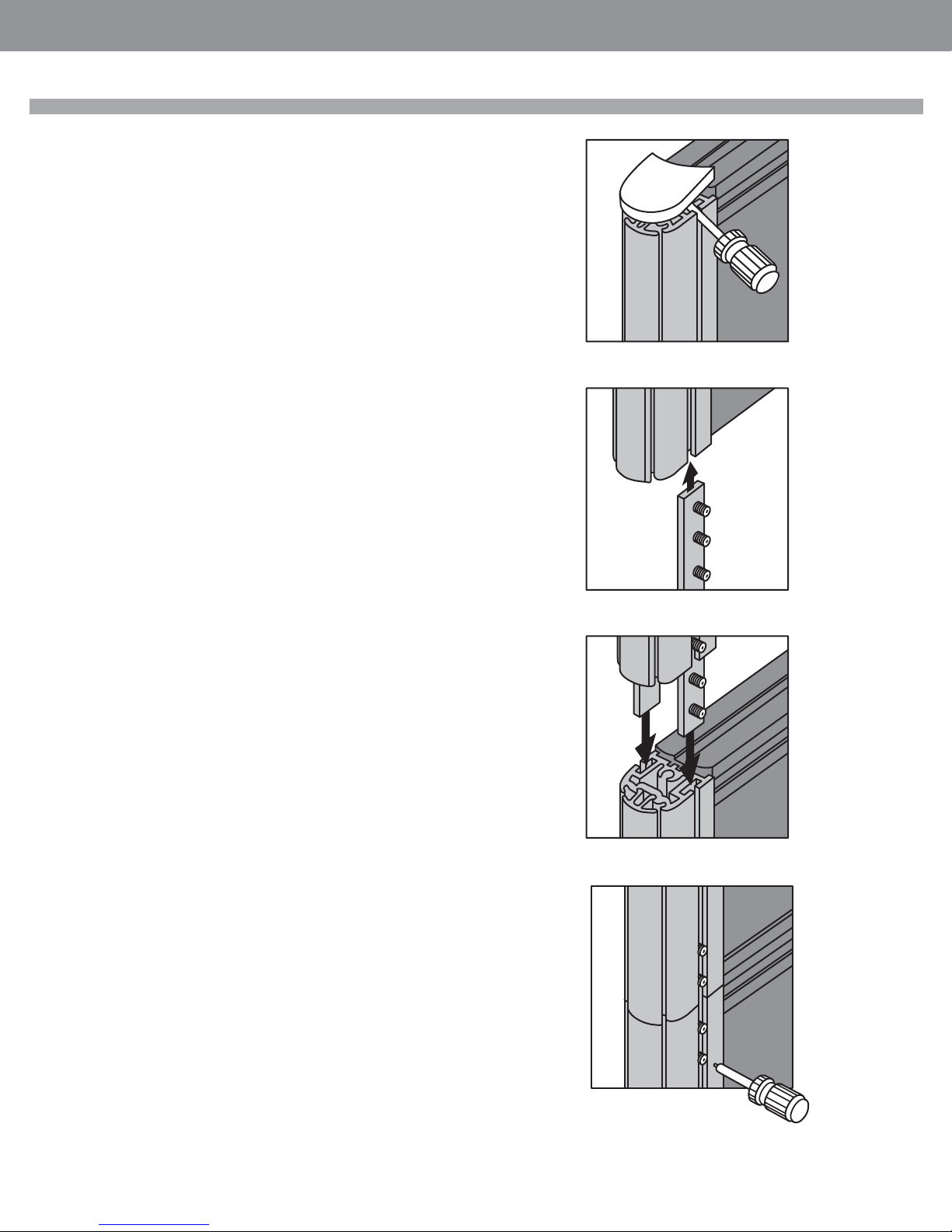
In order to install panel connectors to connect two panels at flexible angle,
STEP 1: remove vertical edge trim,
STEP 2: position spacer A and hinge B over pre-drilled holes at desired height,
STEP 3: secure with two supplied screws (Do not over tighten!) and snap the
vertical edge trims back in place.
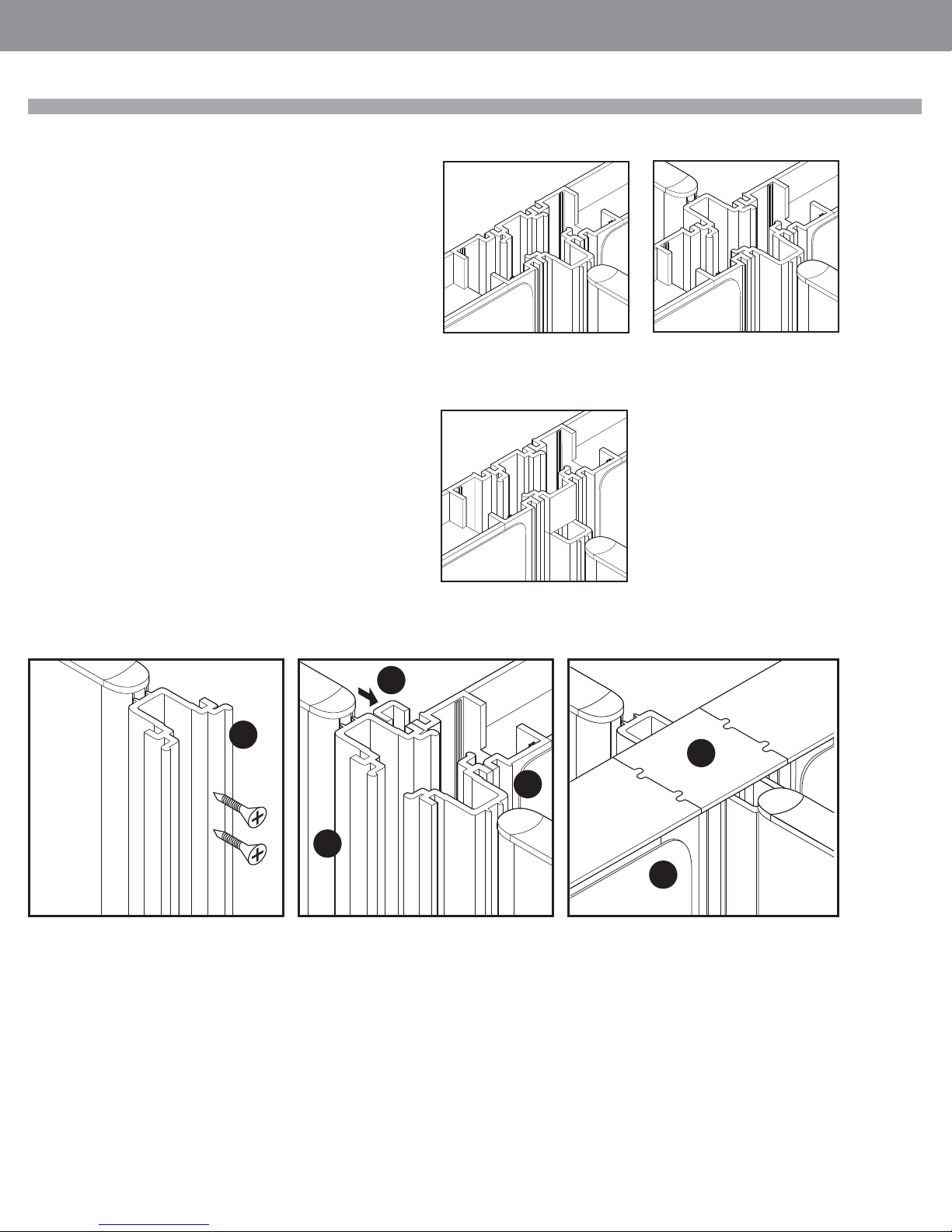
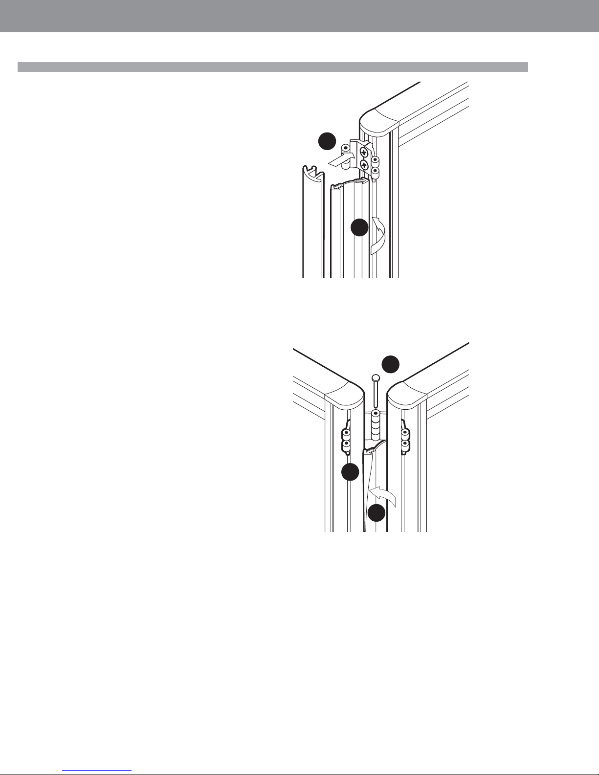
Set the panels to desired angle. Insert top and bottom pins. In order to connect two
straight panels (180°),
STEP 4: Remove vertical edge trims, position two hinges over pre-drilled holes at
desired height and secure with two supplied screws on both panels. Do
not over tighten! Snap vertical edge trims back in place.
STEP 5: Level the first panel, position the second panel so that all hinges overlap
and insert four pins (two at the top; two at the bottom).
STEP 6: To connect 3 panels in a 90°, 3 way configuration, remove panel vertical
edge trims and install two spacer / hinge sets (top and bottom) on both
wing panels.
Install two hinge / hinge sets (top and bottom) on the panel that is going
to be installed between the wing panels.
Replace vertical edge trims, level the first panel, position wing panels so
that all hinges overlap and insert four pins (two at the top; two at the
bottom) as you go along.
STEP 7: To connect three panels in a 120°, three-way configuration (or four
panels in a 90°, four-way configuration.
Remove panel vertical edge trims and install two hinge / hinge sets (top and bot-
tom) on all panels.
Replace vertical edge trims, level the first panel, position remaining panels so that
all hinges overlap and insert four pins (two at the top; two at the bottom) as you
go along. Level the whole panel assembly.
1
4
5
6
2
3
B
A

Page • globalcontract.com4
• Summer 2017
GLOBALContract
Off-Module Panel Connector
INSTALLATION GUIDELINES
To connect two panels in an off-module, “T” configuration remove panel vertical edge
trim and remove all connectors and spacers.
STEP 1: Secure top off-module bracket to panel vertical with supplied screws.
STEP 2: Drive levelers on the second panel all the way in and hold the panel in a tilted
position. Slide it carefully over the top bracket as illustrated, while making sure that the
bracket is seated inside of the top horizontal rail.
STEP 3: Bring the panel carefully into a vertical position and adjust its final location.
STEP 4: Engage bottom off-module bracket in bottom horizontal panel rail.
STEP 5: Secure with supplied screws to panel vertical and level the whole assembly.
STEP 6: Install two set screws in the top bracket to prevent the top bracket from sliding
sideways and tighten carefully with supplied allan key. If the off-modularly connected
panel is higher then the perpendicular one, cut a vertical edge trim (removed earlier
from panel) and snap it onto the panel’s vertical, between top corner cap and top of the
upper, off-module bracket. If the perpendicular panel does not have base cable manager
installed, the bottom of the off-module panel will be exposed. In such instances cut 4
5/8” long pieces from the vertical edge trim and snap it onto the panel’s vertical at
the bottom.

•Pageglobalcontract.com 5
• Summer 2017
GLOBALContract
INSTALLATION GUIDELINES
Wall Adapter
2
Remove panel vertical edge trim on the side facing the wall.
STEP 1: Secure temporarily top bracket to panel vertical member by driving supplied
screw into top hole.
STEP 2: Remove leveler, add supplied nut and lock the bottom bracket between the nut
and the bottom of panels vertical member.
STEP 3: Position levelled panel against the wall and mark the wall (both top and bottom
brackets have notches on either side to indicate anchor location). Use level to mark verti-
cal line on the wall where centre of the panel is going to be, and install wall anchors, not
supplied. The choice of wall anchors depends on the construction and material of the
wall. ( ie. wood, steel, drywall etc..)
Loosen screw holding top bracket just enough to be able to slide the bracket down.
Drive the leveler with the nut out by 25 mm and slide the bottom bracket out.
Secure both brackets to the wall anchors.
STEP 4: Position panel with the screw over the top bracket while making sure that the
leveler is located within the bottom bracket. Adjust leveler while making sure that the top
bracket is seated behind the top screw head.
STEP 5: As soon as the top screw is firmly seated in the top bracket level the panel (us-
ing leveler on the opposite side) and tighten the nut on the leveler to secure the bottom
bracket.
1
3
5

Page • globalcontract.com6
• Summer 2017
GLOBALContract
INSTALLATION GUIDELINES
Diet to Boulevard Slot Connector
The kit consists of : 2 brackets
2 screw anchors
2 # 10-24x3/8” pan head machine screws
2 # 10 lock washers
Ensure that the complete BOULEVARD panel run is level before proceeding
with connecting perpendicular Diet panels.
STEP 1: Slide one screw anchor into panel’s vertical groove and secure it temporarily
below the panel’s top corner cap.
STEP 2: Install the bottom bracket with downward pointing hooks.
STEP 3: Align top of the bottom bracket with the top of the horizontal gap in panel’s bot-
tom rail as illustrated. ensure that both bracket tabs (A) are engaged behind aluminum
lip if panel’s vertical frame member.
STEP 4: Slide one screw with screw anchor up into panel’s vertical groove, into bracket’s
slot and secure by tightening the screw.
STEP 5: Lift the Diet panel and hook it with the secured bottom bracket into slots on
perpendicular Boulevard panel.
STEP 6: Level Diet panel.
STEP 7: Align top bracket’s upward pointing hooks with slots in perpendicular Boulevard
panel while making sure that both bracket’s tabs (B) are engaged behind aluminum lip of
Diet panel’s vertical frame member.
STEP 8: Slide the bracket up until it’s hooks are fully engaged in Boulevard panel slots.
STEP 9: Secure the bracket by tightening the top screw.
3
1
2
5
6
8
B
7
9
4
A

•Pageglobalcontract.com 7
• Summer 2017
GLOBALContract
INSTALLATION GUIDELINES
Diet to Boulevard Slot Connector
STEP 1: Remove panel’s top corner cap by carefully tapping the underside of the cap
through side vertical grooves.
STEP 2: Slide over panel connecting brackets halfway into over panel’s vertical groove
as illustrated.
Tighten only the top set screws in order to keep the brackets in place while leaving the
remaining set screws loose. (Ensure that the two lower set screws are not protruding
through the bracket as these would interfere with base panel’s vertical frame.
STEP 3: Slide the over panel with connecting brackets into the vertical grooves on the
base panel as illustrated.
STEP 4: Push the over panel down from the top while tightening remaining set screws
in all connecting brackets.

Page • globalcontract.com8
• Summer 2017
GLOBALContract
INSTALLATION GUIDELINES
Diet to Boulevard Connecting Kit
Diet - to - Boulevard connecting kit typically consists of two extruded aluminum
profiles. Boulevard strips, screws to secure connecting extruded profile to Diet panel
and a cap.
There are three basic configurations (please note the position and the use of ‘Connec-
tor and Filler profiles):
STEP 1: Begin the actual installation by securing Connector profile to Diet panel’s ver-
tical with supplied screws. Note the asymmetrical shape of connector extrusion and
ensure that the larger side of the connector detail must be on the left side when facing
panel’s vertical extrusion or it would not engage with Boulevard panel interface.
STEP 2: Place Diet-Connector subassembly next to Boulevard panel. Ensure that
bottom of the Diet-BLVD Connector rests on top of self leveling feature at the bottom
of BLVD panels.
STEP 3: Install Boulevard capture strips.
STEP 4: Install Boulevard capture strips.
STEP 5: Install the next Boulevard panel or Aluminum vertical end trim.
STEP 6: Finish by installing top cap (injection molded cap for Boulevard 1 and 2;
aluminum cap for Boulevard System 3)
“T” (even height) “X” (even height
“T” (uneven height)
“X” uneven height requires one
more filler profile
1
3
6
4
2
5

•Pageglobalcontract.com 9
• Summer 2017
GLOBALContract
5
INSTALLATION GUIDELINES
Diet Freestanding Panel Mobile Kit
STEP 1: Remove levelers from the bottom of the panel vertical extrusion.
STEP 2: Align the bracket so the legs with the casters run perpendicular to the length
of the panel.
STEP 3: Slide the bracket up until it fits into the horizontal bottom rail.
STEP 4: Remove the PVC cover and screw the bracket to the panel vertical through
the second bottom hole.
STEP 5: Re-attach the levelers.
1
34
2
5

Page • globalcontract.com10
• Summer 2017
GLOBALContract
Diet Panel Gap Filler Installation
The Diet gap filler is installed into the groove between panel’s aluminum vertical frame
member and extruded PVC end trim. It is the same gap through which panel hinge
connectors protrude. The gap filler fills the gap between Diet panels, from the bottom
edge of the top hinge connector to the top edge of the bottom connector. If there are
more then two hinges connecting the two adjacent panels then trim the length of the
filler so that it fills the gaps between top and the middle hinge and, again, between the
middle hinge and the bottom hinge.
STEP 1: Hold the filler so that one arm of the ‘arrow’ is engaged behind the front edge
of panel’s aluminum vertical frame member.
STEP 2: Snap the extruded PVC end trim onto the panel’s vertical frame member while
ensuring that the second arm of the ‘arrow’ remains engaged behind the extruded
PVC trim.
STEP 3: Connect panels with connector pins.
STEP 4: Arrange the opposite end of the filler so that one ‘arrow’ is engaged along the
full height between the aluminum vertical frame member and extruded PVC end trim.
STEP 5: Proceed from top of the filler and tack the other ‘arrow’ behind the aluminum
frame member and the extruded PVC end trim.
INSTALLATION GUIDELINES
1
2
3
4
5

•Pageglobalcontract.com 11
• Summer 2017
GLOBALContract
90 Degree Configurations approved by UL
The following 90º configurations must be locked with either shelves (figure 1), over-
head (figure 2) or worksurfaces (figure 3 and 4) to be UL listed.
Figure 1 and Figure 2 must use return wing panels of 36” wide minimum.
Figure 1 Figure 2
Figure 3 Figure 4
INSTALLATION GUIDELINES

Page • globalcontract.com12
• Summer 2017
GLOBALContract
Diet Electrical
STEP 1: Make sure that all panel structures and work surfaces are leveled and
securely connected before proceeding with installation of power components.
STEP 2: Identify type and length of specified components and position them in ac-
cordance with layout plans.
Interconnect electrical components while proceeding from Electrical Feed Harness. To
prevent the danger of electric shock, connect the Electrical Feed Harness to the build-
ing power supply only after completing the installation.
Test all Receptacles and ensure that circuits no. 1 and 2 correspond to specified
electrical layout.
STEP 3: Install data and communication cable bundles and terminals.
STEP 4: Walk through; conduct a thorough installation inspection with the client.
WARNING : It is recommended that installation of electrical harness be made under
the supervision of a licensed electrician in accordance with applicable
codes and regulations. Always determine that harness is electrically
connected to only one power supply.
INSTALLATION GUIDELINES
NEUTRAL
GROUND
HOT 2
HOT 1
WHITE
GREEN/BARE
RED
BLACK

•Pageglobalcontract.com 13
• Summer 2017
GLOBALContract
Diet Electrical Components
STEP 1: Duplex Receptacle Block circuit #1 or #2; provides access to power.
STEP 2: Receptacle Block Retainer secures Duplex Receptacle Blocks and Electrical
Feed Blocks to the panel’s bottom horizontal rail.
STEP 3: Duplex Receptacle Block Spacer determines accurate location of Duplex
Receptacle Blocks and Electrical Feed Blocks within panels.
STEP 4: Duplex Receptacle Block to Duplex Receptacle Block Connector connects 2
Duplex Receptacle Blocks in 30” wide panel application.
STEP 5: Interconnect Harness connects 2 Duplex Receptacle Blocks within a panel.
STEP 6: Jumper Harness connects electrical components housed within two adjacent
panels.
STEP 7: Base Feed connects floor distributed building power supply with panel
housed electrical components.
STEP 8: Ceiling Feed (shown with Power Pole) connects above-ceiling distributed
building
power supply with panel housed electrical components.
STEP 9: Ceiling Bezel provides trim for Power Pole.
STEP 10: Diet Panel Raceway Cover with partial receptacle and data knockouts.
STEP 11: Raceway Junction Cover provides an external cover for cables between
panels
INSTALLATION GUIDELINES
1
2
7
5
9
48
6
10
11

Page • globalcontract.com14
• Summer 2017
GLOBALContract
INSTALLATION GUIDELINES
Due to narrow cavity of the raceway, there can only be one Duplex Receptacle Block
installed at given location, protruding through either the inside face or the outside face
of the panel (the Duplex Receptacle Blocks cannot be installed back-to-back). For this
reason, the direction of Duplex Receptacle Blocks within one panel run would typically
alter (one inside, one outside, as illustrated Fig. A). (Panels 36” and wider)
Duplex Receptacle Blocks can be also installed facing in the same direction (Fig. B).
There are four partial knock out holes in each raceway cover.
Confirm which side of the panel the Duplex Receptacle Blocks are going to face and
create opening in raceway covers by removing the desired partial knock-outs.
STEP 1: Determine type and location of an Electrical Feed (ceiling or floor).
Both Electrical Feeds enter the raceway cavity through Receptacle opening the
raceway cover.
The Base Electrical Feed connects to a floor monuments within 6’.
The Ceiling Feed rises up within a dedicated Power Pole. This Power Pole is secured
to the outside of the panel and utilizes a “scoop” in the rear edge of the work surface
to reach the ceiling. The “scoop” must be located immediately above the Receptacle
opening in the Raceway Cover through which the Ceiling Feed is to enter the Raceway
cavity.
STEP 2: Begin the actual installation by threading the Electrical Feed’s flexible conduit
through the Receptacle opening in the Raceway Cover. Thread from the inside out.
STEP 3: Follow the installation specifications and interconnect all components
(Electrical Feed Block, Duplex Receptacle Blocks, Harnesses) on the floor, next to the
panel run.
STEP 4: Snap Receptacle Spacer to the bottom groove of Diet panel frame. Use one
Receptacle Spacer on each end of the panel. Ensure that the Receptacle Spacer rests
snugly next to panel’s vertical extrusion.
Diet Electrical installation
Figure A
Figure B
2
3
4

•Pageglobalcontract.com 15
• Summer 2017
GLOBALContract
INSTALLATION GUIDELINES
Electrical Feed Blocks and Duplex Receptacle Blocks share the same, extruded Mount-
ing Bracket and Mounting Bracket Retainer.
While the following illustrations depict installation of the Duplex Receptacle Block, the
same procedure is used to secure Electrical Feed Block.
STEP 5: Insert the Duplex Receptacle Block mounting bracket into the bottom groove
of the Diet panel frame as illustrated.
STEP 6: Insert the Duplex Receptacle Block retainer into the bottom groove of the Diet
panel frame. Align it with the Mounting Bracket.
STEP 7: Slide the Bracket / Retainer assembly snugly against the Duplex Receptacle
Block Spacer and use an allen key to spread the Bracket and the Retainer in the bot-
tom horizontal frame member.
STEP 8: Repeat the procedure on the opposite end of the panel. Ensure that the
Duplex Receptacle Blocks installed facing the same or opposite side of the panels are
in accordance with your floor plan specifications.
STEP 9: Power can be installed exiting the raceway cover in the left or right direction.
Base Feed:
Choose the direction corresponding with the location of the nearest floor monument.
Ceiling Feed:
Because the Ceiling Feed conduit (within the Power Pole) always rises through a
worksurface “scoop” above the Ceiling Feed panel entry, install the Ceiling Feed
conduit so it always points to the closest edge of a panel.
Close the Raceway Cover.
STEP 10: Hold the Ceiling Feed conduit in the desired direction against the closed
Raceway Cover and place the injection molded Power Cover over the protruding
Electrical Feed Block as illustrated.
STEP 11: Secure the cover with supplied screws.
STEP 12: Thread the Ceiling Feed conduit up, through the worksurface “scoop”.
STEP 13: Remove ceiling tile and slide aluminum Power Pole extrusion down,
through the worksurface “scoop”.
Note: If ceiling mounted objects prevent you from sliding the Power Pole down,
remove worksurface temporarily, but secure the worksurface back to the panels
because it is the scoop cut out in the worksurface that determines accurate location of
the Ceiling Power Pole.
There are two pairs of mounting keyholes punched in the aluminum Diet Power Pole.
One pair is at the base and another pair is just below desk height.
Diet Electrical installation
6
7
5
10
11
13 12

Page • globalcontract.com16
• Summer 2017
GLOBALContract
INSTALLATION GUIDELINES
STEP 14: Align the two desk height keyholes with the groove in the panel’s horizontal,
desk height frame extrusion.
STEP 15: Insert two rectangular anchor nuts with supplied screws through the
keyholes in the Power Pole.
Tighten the screws, while ensuring the Power Pole is vertical.
STEP 16: Align the two bottom keyholes with the groove in the panel’s bottom
frame extrusion.
STEP 17: Insert two rectangular anchor nuts with supplied screws through keyholes
in the the aluminum Power Pole.
STEP 18: With the Power Pole now in its final position, mark the ceiling tile, cut a
tight outline hole and reinstall the ceiling tile.
STEP 19: Pull the Electrical Feed conduit up one side of the Power Pole partition.
Secure the conduit to the junction box strain relief fitting.
STEP 20: Run the data cables up the other side of the partitioned Power Pole and
snap on the Power Pole Cover. It consists of a shorter section (below the
work surface) and a longer section (between the work surface and the
ceiling).
STEP 21: Install the Ceiling Bezel and secure it with two supplied screws.
Check the complete installation of the electrical components and connect to
the building power supply through the adjacent ceiling tile.
WARNING: It is recommended that the installation of the electrical harness
be made under the supervision of a licensed electrician in accordance with
applicable codes and regulations.
SPECIAL NOTE: Always determine that the harness is electrically connected
to the only one power supply.
Diet Electrical installation
19
18
21 20
14
20
15
17
16

•Pageglobalcontract.com 17
• Summer 2017
GLOBALContract
INSTALLATION GUIDELINES
Data and communication cables distributed above ceiling grid typically descend
through a Power Pole and enter the Diet raceway cavity either through a gap between
Diet Raceway Cover at any panel junction, or between the Raceway Cover and the
Raceway Junction Cover.
Similarly, data/communication cables originating in the wall or a floor monument
enter the Diet raceway cavity either through a gap between the Diet Raceway Cover at
any panel junction, or between the Raceway Cover and the Raceway Junction Cover.
Horizontal cable distribution is managed by the Raceway Cover, which opens up on
the floor, allowing for cable lay-in (cable bypass on the outside of the panels junction
point).
Partial knock-outs (2.67” wide x 1.360” high) provided in each Raceway Cover ac-
commodate terminal plates from various vendors.
RACEWAY JUNCTION COVER INSTALLATION:
It is recommended that data cables and power conduits pass from one panel to
another on the same side of the panel.
Universal Raceway Junction Cover accommodates in-line (180o) panels as well as
off-module, “cross” panel configurations:
STEP 1: Insert the upper lip into the panel’s bottom horizontal extrusion.
STEP 2: Slide two rectangular anchor nuts with supplied screws up the groove in the
panel’s vertical frame member and tighten.
Check the complete installation.
Diet Data/Communication installation
2
1

Page • globalcontract.com18
• Summer 2017
GLOBALContract
INSTALLATION GUIDELINES
Cable Management
Office equipment used with Diet panels can be connected (power and data) to
building’s wall outlets, floor monuments (1), or to power and data terminals
under a raised floor. A multiple-circuit Viceversa floor standing Power tower (2)
could be an effective, semi flexible way of branching-off power from floor monu-
ment or a raised floor. Although it is hard-wired to the source, its 6’ of flexible,
liquid-tight conduit allows for a quick relocation.
When Diet components are used in conjunction with Boulevard panels, the Bou-
levard’s internal power distribution system and data / communication cableways
can serve as the primary, service providing “spine” (3).
When raised floors are not available, or when office equipment is to be installed
further away from wall outlets or Boulevard panels, use Viceversa Power towers,
Power clip and surge protected power bar :
Floor-to-ceiling Viceversa Power tower (4) can route a multiple-circuit power and
data / communication cables through ceiling into a point shared by several work
stations.
Floor standing Viceversa Power tower or table mounted Power clip (5) can be
plugged into distant wall outlets or branch-off power / data services perpendicu-
larly away from Boulevard panels and shared by stations.
Similarly, a surge protected power bar (6) can be plugged into distant wall outlets
or Boulevard panels and secured to the underside of a worksurface to provide
power to two stations (depending on specific power requirements of individual
equipment).
Utilize internal capacity of Boulevard panel raceway to organize excess of cable,
use horizontal and leg cable managers integrated into Viceversa tables, or
optional cable manager for Diet panels. The diet panel cable manager attaches to
the bottom of full height Diet panel, or to the bottom of mid rail on Diet panels
without bottom fabric area.

•Pageglobalcontract.com 19
• Summer 2017
GLOBALContract
INSTALLATION GUIDELINES
Diet Cable Manager
Determine length of individual Cable managers and stage them accordingly, as
specified on your plan, in the proximity of their future location.
1) Lay the cable manager flat underneath the panel and lay cable bundles on top
of it. Divide the bundles so that roughly equal amount of cables passes on either
side of the panel leg. This will prevent manager from bulging.
2) As you proceed lifting the manager from the floor, ensure that a notch in
the manager’s bottom fits over internal edge of the panel leg. This will keep the
manager’s sides in a vertical position.
3) Press upper edges of the cable manager into groves on both sides of panel’s
bottom rail.
NOTE: If you use a full depth pedestals ( 24” deep pedestal under 24” deep
worksurface), you may have to slide the pedestal partially out in order to gain an
access to the panel’s cable manager. Diet worksurfaces are provided with two
cutouts to allow for a cord plug to pass between floor and worksurface.
4) Thread cord plug through the cutout.
5) Position cable in the gap between worksurface and panel as required.
6) Use Viceversa optional Cable snake to organize cables between worksurface
level and floor standing CPU or Diet panel cable manager. Surge protected power
bars (DABAR) are provided with mounting keyholes at the back.
7) Establish location of power source, route power bars cord through cable
managers and
8) position underneath the worksurface where the length of the cord allows (pref-
erably in near proximity of the rear cutouts). Measure distance between keyholes
on the Power bar and drive two #6x3/4” wood screws with pan head partially into
the bottom of the worksurface. Slide the Power bar over the screws and ensure a
secure fit.
NOTE: Power bar is also available with a bracket that secures it to panel’s horizon-
tal rails..
9) Plug the cord.
NOTE: Do not connect multiple power bars into one, single-circuit outlet without
ensuring that the total, combined power consumption of all connected equipment
is NOT going to exceed 15 Amps (Canada) or 20 Amps (USA).
WARNING: It is recommended that the installation of the electrical system be
made under the supervision of a licensed electrician and in accordance with
applicable codes and regulations. Hard wired connection to the building power
supply must be done only by a licensed electrician. Do not connect or disconnect
components while the system is under load. Disconnect the main power supply
before servicing or reconfiguration.
4
6
8
9
7
5
3
1
2

Page • globalcontract.com20
• Summer 2017
GLOBALContract
INSTALLATION GUIDELINES
Ensure that all panels are leveled and securely connected before proceeding with
installation of worksurfaces.
Determine type, size and location of worksurfaces.
Determine type and location of worksurface supports and stage them accordingly, in
the proximity of their future location.
Proceed by installing and leveling each consecutive worksurface support and work-
surface in location specified on your plan.
STEP 1: Worksurface universal bracket
STEP 2: Worksurface flat bracket
STEP 3: Gable leg
STEP 4: Pedestal bracket
STEP 5: Corner plate
STEP 6: Transaction top
STEP 7: Off-module support with fixed height Viceversa legs and Worksurface
universal brackets
Worksurface Support
2
1
3
4
5
6
7
Table of contents
Other Global Contract Indoor Furnishing manuals

Global Contract
Global Contract Bridges II User manual

Global Contract
Global Contract Compile User manual

Global Contract
Global Contract Corby User manual

Global Contract
Global Contract Free Fit User manual

Global Contract
Global Contract Bridges II User manual

Global Contract
Global Contract Free Fit Flow Ease Handset User manual

Global Contract
Global Contract Viceversa Bridges User manual

Global Contract
Global Contract Licence 2 User manual