manuals.online logo
Brands
  1. Home
  2. •
  3. Brands
  4. •
  5. Global Fire Equipment
  6. •
  7. Door Lock
  8. •
  9. Global Fire Equipment GFE-DHA User manual

Global Fire Equipment GFE-DHA User manual

Popular Door Lock manuals by other brands

Assa Abloy effeff 827A-IP Mounting instructions

Assa Abloy

Assa Abloy effeff 827A-IP Mounting instructions

Iseo MA1A installation guide

Iseo

Iseo MA1A installation guide

ID Lock 150 user manual

ID Lock

ID Lock 150 user manual

Lockly ACCESS TOUCH PRO user manual

Lockly

Lockly ACCESS TOUCH PRO user manual

iLoq G50S user guide

iLoq

iLoq G50S user guide

SDC Z7835 installation instructions

SDC

SDC Z7835 installation instructions

ilco 452 Installation

ilco

ilco 452 Installation

Samsung shs-h705 user guide

Samsung

Samsung shs-h705 user guide

TRU-BOLT 08102017 user manual

TRU-BOLT

TRU-BOLT 08102017 user manual

CDVI 500-LADJ quick start guide

CDVI

CDVI 500-LADJ quick start guide

Igloohome Deadbolt 2S Metal Grey Installer/user guide

Igloohome

Igloohome Deadbolt 2S Metal Grey Installer/user guide

eSSL FL-300 user manual

eSSL

eSSL FL-300 user manual

Dorma MUNDUS PREMIUM GK 50 Mounting instruction

Dorma

Dorma MUNDUS PREMIUM GK 50 Mounting instruction

SCOOP Pullbloc 4.1 FS Panik Assembly instruction

SCOOP

SCOOP Pullbloc 4.1 FS Panik Assembly instruction

Yale MORTISE 8800 SERIES installation instructions

Yale

Yale MORTISE 8800 SERIES installation instructions

Siegenia KFV AS3500 Assembly instructions

Siegenia

Siegenia KFV AS3500 Assembly instructions

Saflok Quantum ädesē RFID installation instructions

Saflok

Saflok Quantum ädesē RFID installation instructions

ArrowVision Shepherd 210 installation manual

ArrowVision

ArrowVision Shepherd 210 installation manual

manuals.online logo
manuals.online logoBrands
  • About & Mission
  • Contact us
  • Privacy Policy
  • Terms and Conditions

Copyright 2025 Manuals.Online. All Rights Reserved.

GFE-DHA
Addressable Magnetic Door Holder
Instruction Manual V1.0- 06/10 1
The unit is a loop powered addressable
magnetic door release. It does not require
external supply as it is directly powered from
the loop.
Activation of the unit is achieved using cause
and effect programming as used for I/O units.
If power is removed or communication with
the panel is lost the unit will release
automatically after approximately 20
seconds.
A built in loop isolator is provided. When a
short condition exists in either side of the
loop connections, a YELLOW LED will be
turned ON. Its operation will be reset after
the fault condition is removed.
Module is fitted with 3 status leds. The GREEN
LED will flash every time the device is polled
by the addressable panel.
The RED LED, when ON, indicates that the
door release has been activated and it is OFF
after panel power up or reset. When flashing,
it indicates that the door holder is ready to
release. Finally the YELLOW LED will indicate a
fault in the module.
The activation of the module can be achieved
as part of the cause and effect programming
of the panel and it operates in the same way
as an I/O unit. This unit should normally be
added to an IO group and assigned to either a
specific device or zone.
Up to a maximum of 20 of these units can be
fitted on a particular loop.
Built-in Loop Isolator
Addressable Unit
Loop Powered
Loop Powered
4 Status Indicators:
Coms, Fault, Released, Isolator
Max. 20 units per Loop
Weight (Magnet)
Weight (Keeper)
Weight - complete unit boxed
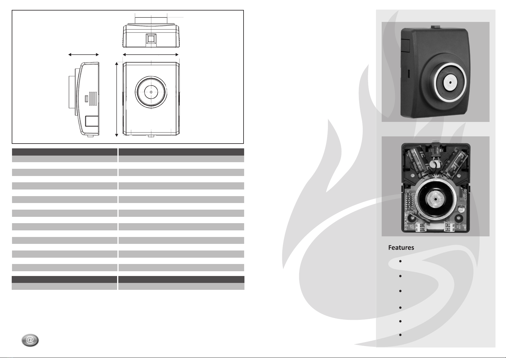
Dimensions (Magnet)
Dimensions (Keeper)
Max. Humidity
Operating Temperature
Magnet Holding Force
Loop Current - Charging
Isolator - Loop Line Resistance
Charge up time
Fail Safe Release Time 1)
Manual Release
Max. Cable Size
Loop Current - Quiescent
Technical Specifications
Supply Voltage
Address Range
7 mA
60 mOhms
25 s
20 s
Push Button - Normally Open
2
2.5 mm
520 g - boxed inc. electronic module
139 g
700 g
112.5 (H) x 84.2 (W) x46.8 (D) mm
55 (H) x 55 (W) x 50 (D) mm
0 ºC to 40 ºC
200 N
95% RH Non-Condensing
Loop Powered - 17V to 30 V DC
1-125
600 uA (450 uA module+150 uA isolator)
1) Fail Safe Release Time is defined as the time taken to release door when removal
of loop power or loss of communication with control panel is detected.
112.5 mm
46.8 mm 112.5 mm
Mechanical Specification
Global Fire Equipment S. A.
MARF - Armazéns F3 e F4, Sítio do Guelhim, Estói, 8009-021 FARO, PORTUGAL
Tel: + 351 289 896 560 Fax: + 351 289 865 587
Sales [email protected] Technical Support [email protected]
GFE-DHA
Order Code
Addressable Magnetic Door Holder
Address Settings
1234 5 6 7 8 1234 5 6 7 8 1234 5 6 7 8 1234 5 6 7 8 1234 5 6 7 8 1234 5 6 7 8 1234 5 6 7 8 1234 5 6 7 8
1234 5 6 7 8 1234 5 6 7 8 1234 5 6 7 8 1234 5 6 7 8 1234 5 6 7 8 1234 5 6 7 8 1234 5 6 7 8 1234 5 6 7 8
1234 5 6 7 8 1234 5 6 7 8 1234 5 6 7 8 1234 5 6 7 8 1234 5 6 7 8 1234 5 6 7 8 1234 5 6 7 8 1234 5 6 7 8
1234 5 6 7 8 1234 5 6 7 8 1234 5 6 7 8 1234 5 6 7 8 1234 5 6 7 8 1234 5 6 7 8 1234 5 6 7 8 1234 5 6 7 8
01
09
17
25
02
10
18
26
03
11
19
27
04
12
20
28
05
13
21
29
06
14
22
30
07
15
23
31
08
16
24
32
1234 5 6 7 8 1234 5 6 7 8 1234 5 6 7 8 1234 5 6 7 8 1234 5 6 7 8 1234 5 6 7 8 1234 5 6 7 8 1234 5 6 7 8
1234 5 6 7 8 1234 5 6 7 8 1234 5 6 7 8 1234 5 6 7 8 1234 5 6 7 8 1234 5 6 7 8 1234 5 6 7 8 1234 5 6 7 8
1234 5 6 7 8 1234 5 6 7 8 1234 5 6 7 8 1234 5 6 7 8 1234 5 6 7 8 1234 5 6 7 8 1234 5 6 7 8
1234 5 6 7 8 1234 5 6 7 8 1234 5 6 7 8 1234 5 6 7 8 1234 5 6 7 8 1234 5 6 7 8 1234 5 6 7 8
33
41
49
57
34
42
50
58
35
43
51
59
36
44
52
60
37
45
53
61
38
46
54
62
39
47
55
63
40
48
1234 5 6 7 8
56
1234 5 6 7 8
64
1234 5 6 7 8 1234 5 6 7 8 1234 5 6 7 8 1234 5 6 7 8 1234 5 6 7 8 1234 5 6 7 8 1234 5 6 7 8 1234 5 6 7 8
1234 5 6 7 8 1234 5 6 7 8 1234 5 6 7 8 1234 5 6 7 8 1234 5 6 7 8 1234 5 6 7 8 1234 5 6 7 8 1234 5 6 7 8
1234 5 6 7 8 1234 5 6 7 8 1234 5 6 7 8 1234 5 6 7 8 1234 5 6 7 8 1234 5 6 7 8 1234 5 6 7 8 1234 5 6 7 8
1234 5 6 7 8 1234 5 6 7 8 1234 5 6 7 8 1234 5 6 7 8 1234 5 6 7 8 1234 5 6 7 8 1234 5 6 7 8 1234 5 6 7 8
65
73
81
89
66
74
82
90
67
75
83
91
68
76
84
92
69
77
85
93
70
78
86
94
71
79
87
95
72
80
88
96
1234 5 6 7 8 1234 5 6 7 8 1234 5 6 7 8 1234 5 6 7 8 1234 5 6 7 8 1234 5 6 7 8 1234 5 6 7 8 1234 5 6 7 8
1234 5 6 7 8 1234 5 6 7 8 1234 5 6 7 8 1234 5 6 7 8 1234 5 6 7 8 1234 5 6 7 8 1234 5 6 7 8 1234 5 6 7 8
1234 5 6 7 8 1234 5 6 7 8 1234 5 6 7 8 1234 5 6 7 8 1234 5 6 7 8 1234 5 6 7 8 1234 5 6 7 8 1234 5 6 7 8
1234 5 6 7 8 1234 5 6 7 8 1234 5 6 7 8 1234 5 6 7 8 1234 5 6 7 8
97
105
113
121
98
106
114
122
99
107
115
123
100
108
116
124
101
109
117
125
102
110
118
103
111
119
104
112
120
Switches 1-7
used to configure the module’s address.
Switch 8
Not used
1234 5 6 7 8
ON
OFF
Address Switches binary weights
1 on =1
2 on =2
3 on =4
4 on =8
5 on =16
6 on =32
7 on = 64
1234 5 6 7 8
ON
OFF
Loop
Out
Loop
Return
CONNECTIONS & OPERATION
LOOP
OUT
LOOP
RETURN
PANEL
This device is polarized
LOOP
IN/OUT
LOOP
IN/OUT
1234 5 6 7 8
ON
OFF
Isolator LED is ON when
there is a short circuit
in the loop
Flashes when device is interrogated
by panel.
ON when door release has been
activated. OFF on POWER UP or
panel reset. Flashing when ready
to release.
Fault Indicator.
Address
Loop In Loop Out
Short Circuit
Loop Voltage = 0V
Short Circuit YELLOW LED indicators are ON
Maximum no. of devices between 2 Isolators: 32 (EN54 pt.2) - 20 (BS5839)
ISOLATOR