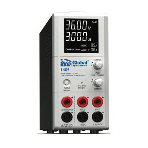
Global Specialties 1403 User manual

1
Safety Summary
The following safety precautions apply to both operating and
maintenance personnel and must be observed during all phases
of operation, service, and repair of this instrument. Before applying
power, follow the installation instructions and become familiar with
the operating instructions for this instrument.
GROUND THE INSTRUMENT
To minimize shock hazard, the instrument chassis and cabinet must
be connected to an electrical ground. This instrument is grounded
through the ground conductor of the supplied, three-conductor ac
power cable. The power cable must be plugged into an approved
three-conductor electrical outlet. Do not alter the ground connection.
Without the protective ground connection, all accessible conductive
parts (including control knobs) can render an electric shock. The
power jack and mating plug of the power cable meet IEC safety
standards.
DO NOT OPERATE IN AN EXPLOSIVE ATMOSPHERE
Do not operate the instrument in the presence of ammable
gases or fumes. Operation of any electrical instrument in such an
environment constitutes a denite safety hazard.
KEEP AWAY FROM LIVE CIRCUITS
Instrument covers must not be removed by operating personnel.
Component replacement and internal adjustments must be made by
qualied maintenance personnel. Disconnect the power cord before
removing the instrument covers and replacing components. Under
certain conditions, even with the power cable removed, dangerous
voltages may exist. To avoid injuries, always disconnect power and
discharge circuits before touching them.
DO NOT SERVICE OR ADJUST ALONE
Do not attempt any internal service or adjustment unless another
person, capable of rendering rst aid and resuscitation, is present.
DO NOT SUBSTITUTE PARTS OR MODIFY THE INSTRUMENT
Do not install substitute parts or perform any unauthorized
2
modications to this instrument. Return the instrument to Global
Specialties (Cal Test Electronics) for service and repair to ensure
that safety features are maintained.
WARNINGS AND CAUTIONS
WARNING and CAUTION statements, such as the following
examples, denote a hazard and appear throughout this manual.
Follow all instructions contained in these statements.
A WARNING statement calls attention to an operating procedure,
practice, or condition, which, if not followed correctly, could result in
injury or death to personnel.
A CAUTION statement calls attention to an operating procedure,
practice, or condition, which, if not followed correctly, could result in
damage to or destruction of parts or the entire product.
WARNING
Do not alter the ground connection. Without the protective ground
connection, all accessible conductive parts (including control knobs)
can render an electric shock. The power jack and mating plug of the
power cable meet IEC safety standards.
WARNING
To avoid electrical shock hazard, disconnect power cord before
removing covers. Refer servicing to qualied personnel.
CAUTION
Before connecting the line cord to the AC mains, check the rear
panel AC line voltage indicator. Applying a line voltage other than
the indicated voltage can destroy the AC line fuses. For continued
re protection, replace fuses only with those of the specied voltage
and current ratings.
CAUTION
This product uses components which can be damaged by electro-
static discharge (ESD). To avoid damage, be sure to follow proper
procedures for handling, storing and transporting parts and


4
1.1 Controls & Indicators
Figure 1 Panel Diagrams
1. Power Switch. Turns the power supply on–off, when it is
on the front display lights up.
2. AC Input Socket with Fuse
3. Concealed Fuse Box. Pry open the cover to get to the
fuse.
4. 3.3V/5 VDC Selection Switch. For Aux Output 1
5. Output Voltage Knob. Push the knob to toggle the
coarse and ne tuning.
6. Output Current Tuning knob. Push the knob to toggle
the coarse and ne tuning.
7. Output On/Off Button. Push this button to turn the Main
output ON/OFF. For Main Output & Aux Outputs, push and

5
hold this button for 3 seconds to turn the Main and Aux
outputs OFF. Push this button again to turn them ON.
8. Main Output Terminal Positive (+). Red color.
9. Main Output Terminal Negative (-). Black color
10. Aux Output 1 Terminal Positive (+). Red color. 3.3 VDC
or 5 VDC selectable.
11. Aux Output 1 Terminal Negative (-). Black color. 3.3
VDC or 5 VDC selectable.
12. Aux Output 2 Terminal Positive (+). Red color. Fixed 12
VDC.
13. Aux Output 2 Terminal Negative (-). Black color. Fixed
12 VDC.
14. LCD Display Panel. Shows: 4 digit voltmeter, ammeter,
(CV) constant voltage mode, (CC) constant current mode,
Output Terminal on/off state, 2 digit Aux Output ammeter
15. Aux 1 Output Voltage Indicator
16. Reserved. Factory internal use only.
17. Ground Terminal
2 Operating the Power Supply
1.1 Operating Environment
z10-80% R.H.
zMaximum relative humidity 80% for temperature up to 31°C
decreasing linearly to 50% relative humidity at 40°C.
zAltitude up to 2000 m
zInstallation category: CAT 2
zPollution degree: 2
zMains supply voltage fluctuation up to ±10% of the normal
voltage

6
1.2 Connection and Operation Procedure
1. Check the rating label and plug in to AC mains.
2. Switch on the power supply and the LCD display should
be on at the same time.
3. The (CV) icon should be shown on the display.
4. Turn to current volume knob (6) to maximum clockwise if
you do not require lower Current limiting value, otherwise
do the preset the (CC) limiting procedure.
5. Set your desired output voltage and then turn off the
output terminal by push button (7).
6. Connect to your load positive to positive and negative to
negative.
7. Turn on the output terminal again and check if display
shows (CV).
8. If display shows (CC), either your preset current limiting
value is too low or your load requires more voltage and
current. You need to re-access the voltage and current
requirement of your load and increase the voltage or
current accordingly until (CV) appears.
1.3 Connecting the 3 outputs
(Using the 1405, 1-36 V, 0.25-3 A as an example)
All the three outputs are fully isolated from ground and with each
other so that it is possible to make cross connections to power a
circuit board or device that requires for example: +3 or +5 V, +12 V
or -12 V and 1-36 V as shown in Figure 2.
Test Equipment Depot - 800.517.8431 - 99 Washington Street Melrose, MA 02176
TestEquipmentDepot.com

7
Figure 2
The variable main output is set for 12 V and it is assigned as the
+12 V source (available maximum current 3 A)
Note the variable main output can be set for other voltage (1-36 V)
such as 16 V.
The xed 12 V is made as the - 12 V source (available maximum
current 0.5 A).
The xed 5 V is made as the +5 V source (available maximum
current 0.5 A).
1.4 CC and CV Mode
This power supply is designed to operate as a constant voltage
source or as a constant current source. Automatic crossover to
either mode of operation occurs when the load condition changes
as follows:
1.4.1 Constant Voltage (CV), Automatic Crossover &
Constant Current (CC)
The power supply functions as a constant voltage source (CV) as
long as the load current is less than the preset current limiting value.
When the load current is equal to or greater than the preset current
limiting value, the power supply will automatically cross over to the
constant current mode, voltage will drop, (CC) will show on the LCD
display panel and it will operate as a constant current source.
When the load current drops below the preset current limiting value,

8
the supply returns to constant voltage (CV) mode.
1.4.2 Set the Output Voltage and Presetting Current
Limiting Value (CC)
Turning the voltage or current knob to set your desired values.
Quick pushes on the knobs will move the decimal place for fast
tuning.
Turn the knob when the desired number column is ashing
otherwise you need to repeat quick pushes again.
One quick push on the current knob to see the preset current
limiting value.
1.5 Aux. Output 1 Voltage Selection
Move the switch (4) at the back of power supply for selection of 3.3
or 5 VDC. At 3.3 VDC setting, indicator (15) is Off and at 5 VDC
setting indicator (15) is On.
1.6 Connecting outputs in series
(Using 1405 as an example)
You can have a 17 V xed output by connecting the 5 V in series
with the 12 V outputs.
The 2 outputs (Aux.1) can be connected in series to make a
variable 5 V to 41 V with maximum current 2 A (Figure 3).
The 3 outputs can be connected in series to make a variable 17 V
to 53 V with maximum current 1 A, (Figure 4).
There are other combination of cross connections for different
positive and negative output voltages.
Figure 3

9
Figure 4
1.7 Tracking Output Over Voltage Protection (OVP)
This is to protect the connected load in the event that the output
voltage control circuit malfunctions, the maximum output voltage
will not exceed 30% of the adjusted voltage value at the time of the
operation.
1.8 Over Temperature Protection
When the temperature inside the power supply becomes higher
than a pre-determined value, the output voltage and current of the
power supply will automatically decrease to zero to prevent damage
to power supply. When the temperature inside the power supply
returns to normal then the power supply will automatically return to
operation again.
3 Specications
All specications apply to the unit after a temperature stabilization
time of 15 minutes over an ambient temperature range of 25 °C ± 5
°C.
1403 1405
Input Voltage
(Universal input)
100–240 VAC, 50/60
Hz 100–240 VAC, 50/60 Hz
Full Load Input
Current at 230 VAC 0.83 A 0.83 A
Output Voltage
Adjustable Range 1.0 – 20 VDC 1.0 – 36 VDC

10
Output Current
Adjustable Range 0.25 – 5 A 0.25 – 3 A
Voltage Regulation
Load from 10% to
90% Variation 70 mV 70 mV
Line from 90 to 264
VAC Variation 25 mV 25 mV
Ripple & Noise
(peak to peak) ≤120 mV ≤150 mV
Current Regulation
Load from 10% to
90% Variation 50 mA 50 mA
Line from 90 to 264
VAC Variation 20 mA 20 mA
Ripple & Noise
(peak to peak) ≤50 mA ≤50 mA
Switching Operation
Frequency 50 kHz to 150 kHz 50 kHz to 150 kHz
Aux Output 1 Fixed 3.3 /5 VDC. 1.8
mA cont. 2 A Max.
Fixed 3.3 /5 VDC. 1.8
mA cont. 2 A Max.
Aux Output 2 Fixed 12 VDC, 800 mA
cont. 1 A Max.
Fixed 12 VDC, 800 mA
cont. 1 A Max.
Power Factor >0.9 >0.9
Efciency at
Maximum Power ≥80.5% ≥80.5%
Volt and Amp
Control Type Rotary Encoder Rotary Encoder
Voltmeter and
Ammeter Display 4 Digit LCD 4 Digit LCD
Voltmeter Accuracy 5 counts, V<5 V
±0.2%+5 counts, V≥5 V
5 counts, V<5 V
±0.2%+5 counts, V≥5 V
Ammeter Accuracy 15 counts, I≤1 A
±0.5% +6 counts, I>1 A
15 counts, I≤1 A
±0.5% +6 counts, I>1 A
LCD Indication CC, CV, Amp, Volt, Output ON-OFF, Aux output
current
Protection Short Circuit, Overload, Over Temperature,
Tracking OVP

11
CE Approvals LVD: EN 61010, EMC: EN 55011
Cooling System Natural Convection
Dimensions
(WxHxD) 70 x 150 x 250 mm (2.8 x 6.0 x 9.8 in)
Weight 2 kg (4.4 lbs)
Remarks All data based on 230 V/50 Hz
Specications are subject to change without notice. To ensure the
most current version of this manual, please download the current
version from our website: globalspecialties.com.
4 Service and Warranty Information
1.1 Limited One-Year Warranty
Cal Test Electronics warrants this product to be free from defective
material or workmanship for a period of 1 year from the date of
original purchase. Under this warranty, Cal Test Electronics is
limited to repairing the defective device when returned to the
factory, shipping charges prepaid, within the warranty period.
Units returned to Cal Test Electronics that have been subject to
abuse, misuse, damage or accident, or have been connected,
installed or adjusted contrary to the instructions furnished by Cal
Test Electronics, or that have been repaired by unauthorized
persons, will not be covered by this warranty.
Cal Test Electronics reserves the right to discontinue models,
change specications, price, or design of this device at any time
without notice and without incurring any obligation whatsoever.
The purchaser agrees to assume all liabilities for any damages
and/or bodily injury which may result from the use or misuse of this
device by the purchaser, his employees, or agents.
This warranty is in lieu of all other representations or warranties
expressed or implied and no agent or representative of Cal
Test Electronics is authorized to assume any other obligation in
connection with the sale and purchase of this device.

12
1.2 Calibration and Repair
If you have a need for any calibration or repair services, please visit
us on the web at: globalspecialties.com. See the “Service” tab. Or
contact us via the “Contact” tab. You may also contact us at:
Test Equipment Depot - 800.517.8431 - 99 Washington Street Melrose, MA 02176
TestEquipmentDepot.com

20160620
Other manuals for 1403
1
This manual suits for next models
1
Table of contents
Other Global Specialties Power Supply manuals

Global Specialties
Global Specialties 1505 User manual

Global Specialties
Global Specialties 1410 User manual

Global Specialties
Global Specialties 1310 User manual

Global Specialties
Global Specialties 1412 User manual

Global Specialties
Global Specialties 1368 User manual

Global Specialties
Global Specialties 1325 User manual

Global Specialties
Global Specialties 1320 User manual

Global Specialties
Global Specialties 1403 User manual

Global Specialties
Global Specialties 1415 User manual

Global Specialties
Global Specialties 1302B User manual